
Disclaimer: My goal is to outline the phases I used to help troubleshoot my G08 without an all or nothing test every time (which could have gotten really expensive). The G08 FAQ V 1.14 has a vast amount of detail and was invaluable and needs to be read through completely. I’ve repaired a few GO8’s and have had good luck bringing them up in stages this way. If I have anything wrong, please let me know.
Note: I strapped my transformer to lug#2 and lug#4. This puts exactly 90 vac to the power connector for the monitor based on the line voltage at my shop. If you line voltages are different – you will have some variation.
Start with restoring deflection:
Verify operation after each start up stage. Anything that is wildly off or missing should be researched / resolved before moving forward. At this stage I have recapped the chassis and tested all of the transistors, diodes and large power resistors in circuit as much as possible. Inspected the board for obvious physical damage and checked for flimsy wire connections etc.
Disconnect the following from the deflection board: Power transistors from the paddleboards, yoke, HV unit and video input cable. Leave only the fan and degauss coil connected. Power up the deflection board and be ready to shut it down quickly if anything ‘bad looking’ happens. All of the marked on-board voltages should be checked. If the fan is humming along and everything seems ok…
Clip your negative meter lead to the frame and check the voltages at the PCB:
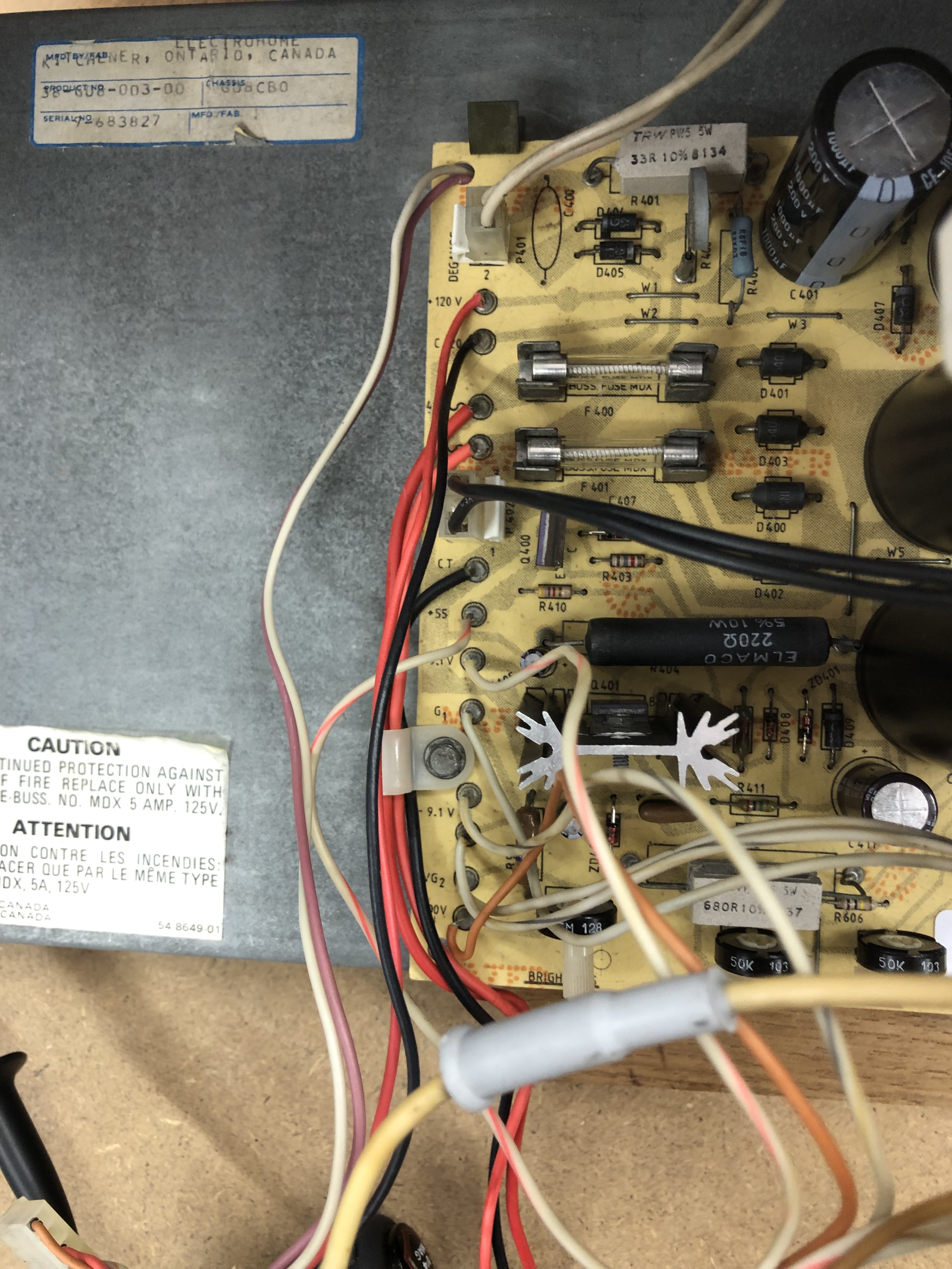
Along the left side of the deflection board you can check:
- +120 vdc
- +9.1vdc
- -9.1vdc
- @R406 (large wire wound resistor behind the V. Center pot) – test the right side for -63VDC
None will be precise since they are unregulated, but all should be pretty close.
Carefully check the pins on the paddleboards. It’s pretty easy to slip and short something – or – use an empty Molex wire connector shell and slip it over the paddle board connector and use it as a guide to prevent the meter lead from slipping.
**** Update – Received some feedback and these voltages can vary depending on the position of the centering X Y pots. Next time I have my G08 on the bench.. I will update the voltage table to reflect the new info. These voltages are with them centered – for the most part ***
600 / 700 Section Paddle connectors – marked on the PCB
| Pin | No Video Connection |
| C | +60.5 vdc |
| B | -58.8 vdc |
| E | -58.8 vdc |
| E | -58.8 vdc |
| Key | |
| B | -58.8 vdc |
| C | -60.4 vdc |
If these voltages are not present, stop and look for issues on the deflection board. I’ve seen the -58.8 voltages with one missing or down around -50v. If so, there is an issue in the circuit right before the deflection paddle.
Connect the power transistors to the paddleboards:
On my monitor, two of the power transistor sockets have resistors on them. I verified all the transistors loose and tested for continuity and shorts. Most important is that the transistor cases and pins are not shorted to the heat sink. If all is well, no fuses blow and no problems. Be sure to check the transistors thoroughly – I’ve had good voltage drop B-E, B-C – but had E-C shorts! A missed Emitter-Collector short will blow up a bunch of stuff (ask me how I know)
Test yoke outputs:
Here you can use a 4 position Molex connector shell for the yoke test. Check X and the Y side with your meter set to DC. It’s pretty tight down there between the paddle boards and the Molex shell slipped over the pins helps keep the meter lead from shorting against other pins.
| Yoke Connector | No Video Connection |
| X – Pin 4 | -59 vdc |
| Y – Pin 1 | -59 vdc |
At this point it will be pretty steady since there is no XY input yet.
Connect your video signal cable and recheck the voltages. This time, if all is well, you will see both of them varying considerably. That is a great sign! Deflection is getting through to the yoke connection. Voltage movement can vary from +60 to – 60 vdc.
Connect the yoke to the deflection board.
Now on power up you should be able to hear deflection chatter. Verify deflection by connecting to a scope.

Connect the scope to Pin 1 (Y axis) Pin 2 (X axis) of the high voltage 10 Pin Molex. You will need to insert a male header to connect the leads. If you don’t have the game on the scope, something is not working on the deflection board and it should be resolved before moving forward.
Bringing up the HV unit:
With the ground of your meter clipped to the monitor frame, check to be sure your signals are getting to the 10 pin HV KK connector. It should not be connected to the HV unit at this point. Video cable is connected.
| Pin | Description | Voltages |
| 1 | Y input | +2-3 vdc moving |
| 2 | X input | +2-3 vdc moving |
| 3 | IC power | -9.2 vdc |
| 4 | IC power | +9.0 vdc |
| 5 | GND | |
| 6 | GND heater | |
| 7 | Heater | 2.2 vac (only when connected to HV Unit) |
| 8 | +130 vdc | |
| 9 | NC | Key |
| 10 | G2 (?) |
These are the numbers I got – they vary a little from the documentation.. The heater will read 0vdc unless the HV unit is connected to the deflection board.
Pin 7 is the heater voltage and its created on the HV unit. All of the documentation I found says 6.3 vac for the heater. I have to look into it further, but I’m assuming the frequency and a few other things are effecting the reading? Best I can get is 2.2vac.
Test voltage regulator:
Disconnect the video cable and connect the the deflection board to the HV unit.
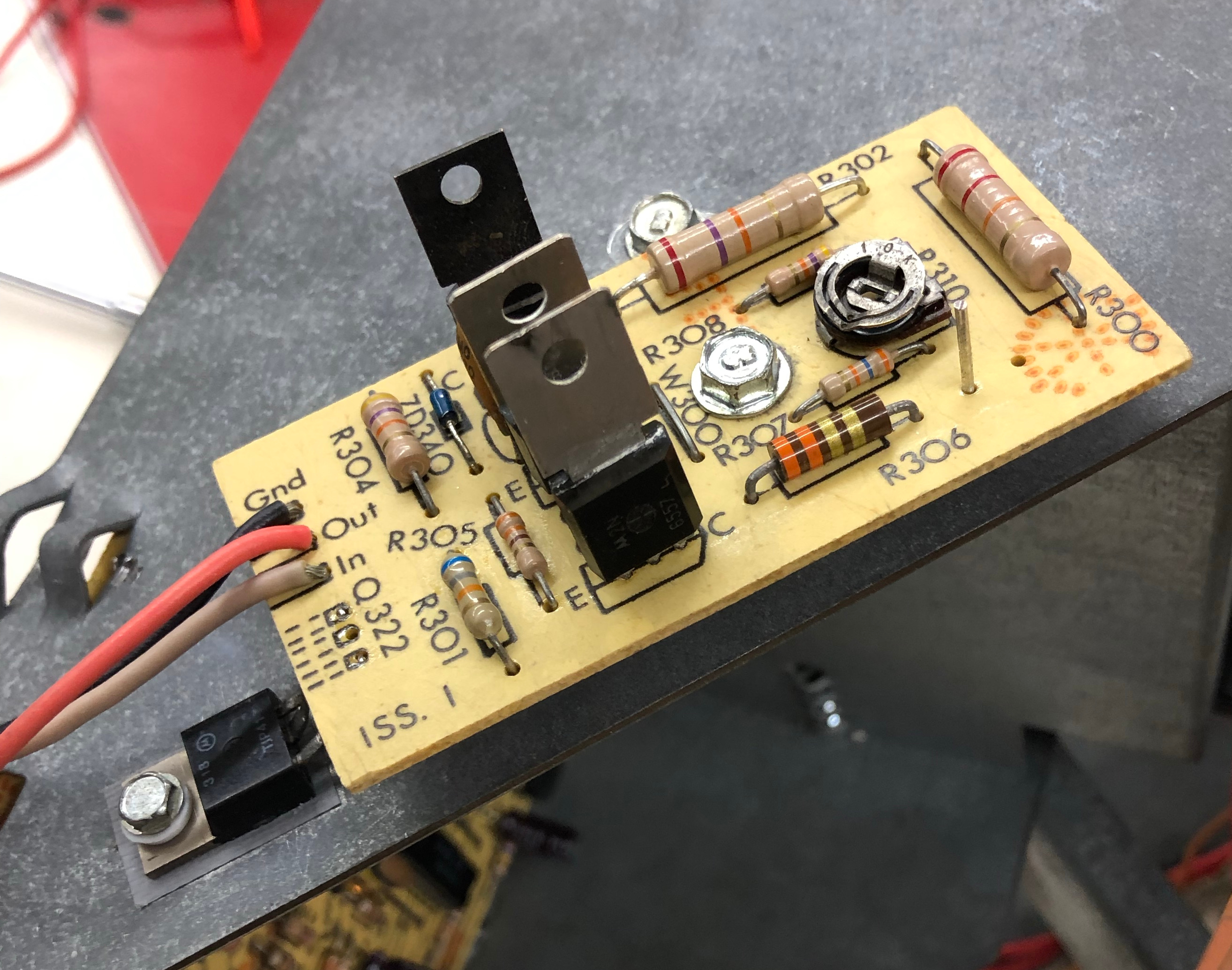
Q322 is a pain – it has to be just right to fit properly and its easy to pull the foil traces on the back of the regulator board. Adding a post (clipped capacitor leg works great) as a test point at R306 makes it much easier to clip onto the board when the unit is on place. With the video cable disconnected – power up the HV unit and check for 100vdc at the test point. You can adjust it with R310. You want it stay in the range 94v-102v.
The HV unit is awkward to have floating around while working with it unscrewed from the frame, but a bit of a necessity. There is a bottlecap transistor on the bottom – be careful not to have it touch the frame – put something under the HV unit to insulate it from touching (cardboard works fine).
At this point it’s time to power up with a video signal and make sure the HV unit is adjusted correctly. Up to now there has not been any actual vectors on the screen.
All the little items to adjust after first fullpower up:
- Brightness
- Horizontal size
- Vertical size
- Horizontal center
- Vertical Center
- Focus
- Colors and cutoffs on the neck board
I normally adjust these on the diag screen from Star Trek. The color bar screen with the box corners I adjust so the box is 1/2″-3/4″ inside the screen and centered. No need to overdrive a G08.. Once the initial flurry of activity is over..
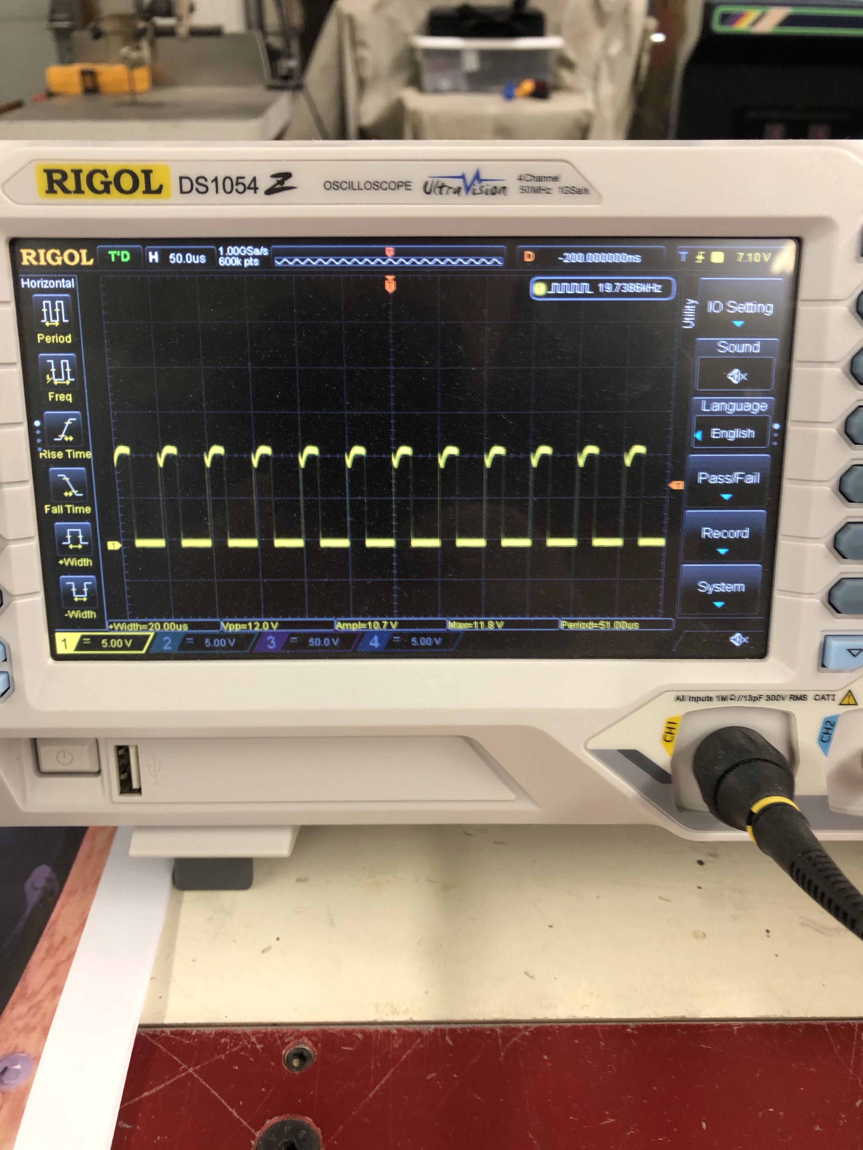
Adjusting the duty cycle:
Jumper TP1 in the HV unit to the frame.
Connect a scope to Q902’s collector, best done with a mini-grabber. You adjust R918 for 20us on and 30us off. Many need to go back and forth with R917 a bit to get it right. Power up with the video signal connected.
Adjust high voltage at anode cup:
Jumper TP1 still connected to the frame.
Remove the RGB wire from the XY control board at the stack. Leave the XY timing board connected.
Setup your HV Probe. I use a spring clamp to prop it up in place. I don’t care for holding them as one little move and I may accidentally spring the clip and have a loose anode cup jumping around.

Adjust R917 to 21kv at the anode cup.
Adjust R933 for 0 vdc:
Remove jumper between TP1 and GND.
Connect meter to TP1 and GND.
Adjust R933 for 0vdc
Reconnect the RGB-4 color wire at the XY Controller board.
Check overall monitor adjustments one last time.
Mods I used:
- Replaced all round pin headers with standard square pin headers
- Repinned KK connectors with Trifuricon pins
- Added TP2 to 100v regulator board
- Added keys to the paddleboards
Less common Parts List:
- R253, 254 – for 600 section paddleboard
- R203, R204 – for 700 section paddleboard
- MJ21196G – Deflection power transistors
Helpful Links:
- Bitronix Star Trek Site – Parts Cross reference and more
- Star Trek Owners Manual – More reference material
- Good KLOV Thread – General G08 discussion
- Good regulator mod and HV Calibration – Added TP2 to regulator board
- G08 FAQ V 1.14 – The latest I believe, there are a lot of old links to prior versions
- G08 Schematics – Printed large sheet at Staples, worth it!
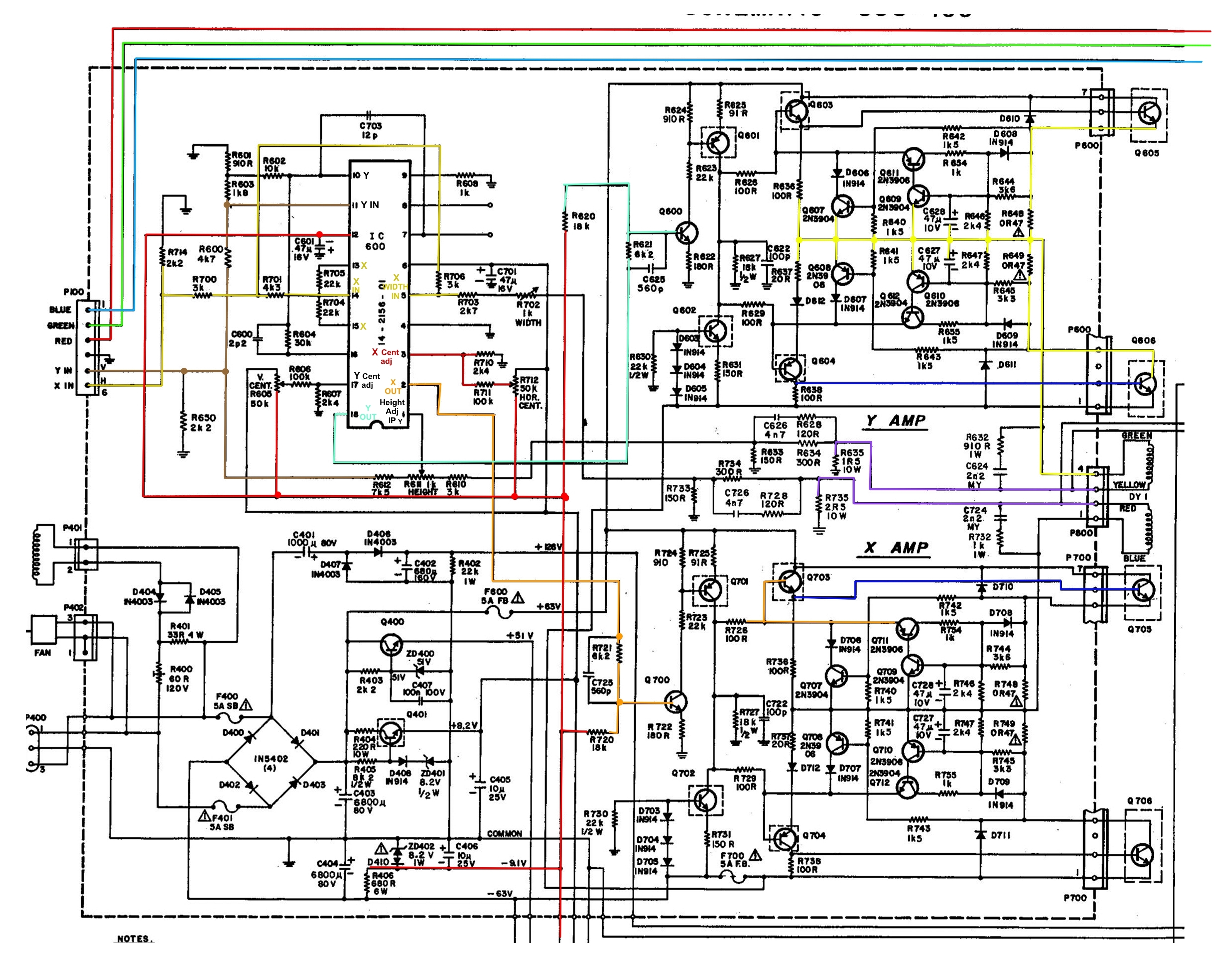
- G08 Schematic with color coded signal – Helpful in tracking down the X Y path..
- Sega Gremlin Color XY Monitor Manual – Yet another variant of the documentation
- Arcade Jason G08 repair video – Got insight into testing the deflection board
- 100V HV Regulator Mod – I didn’t do this – but this could be very useful for someone
- Vector Vault – All things G08 and G80

[…] G08 Power up sequence […]
[…] G08 chassis started as a learning experience which resulted in me creating a G08 Startup sequence/guide. Since then I have worked on a number of them for friends. Since my first one was […]