
*** Newest Entries always added to the bottom ***

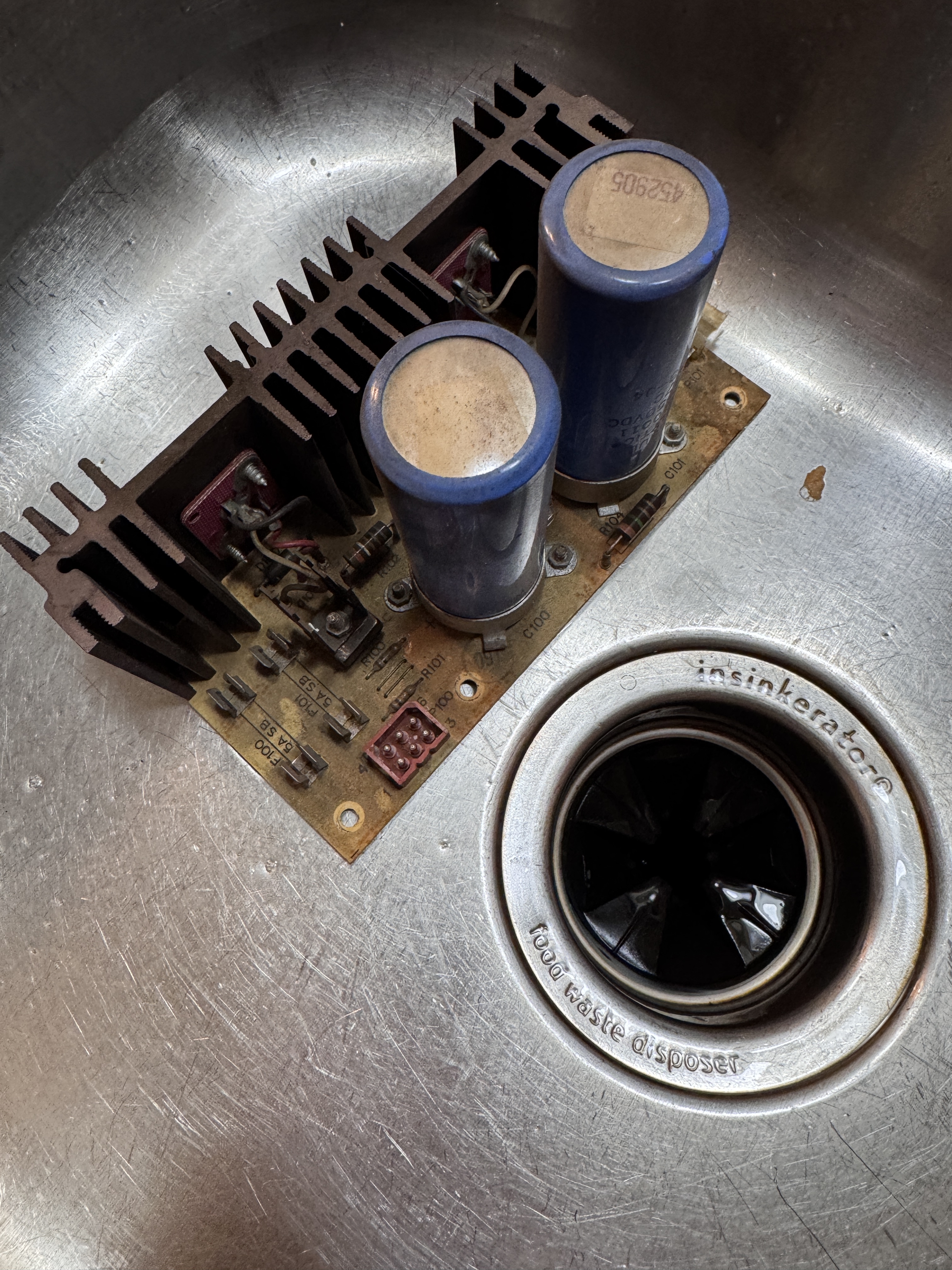
There are a few issues with the monitor. The owner told me the spot killer was on, I didn’t even try it myself. R100 and R101 had burned up and been replaced in the past. These can be bypassed per Atari. I checked the resistance and R101 was good, but R100 was failing and was up to about 50M of resistance.
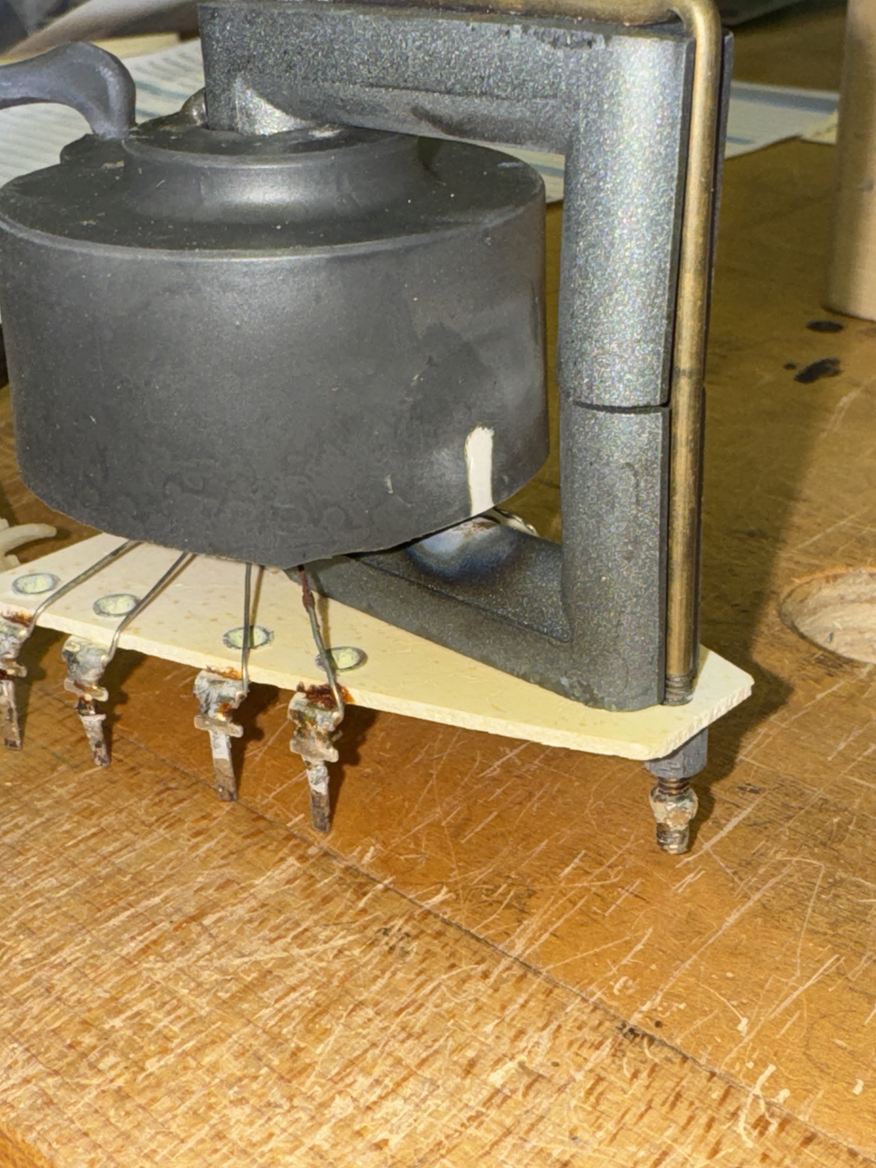
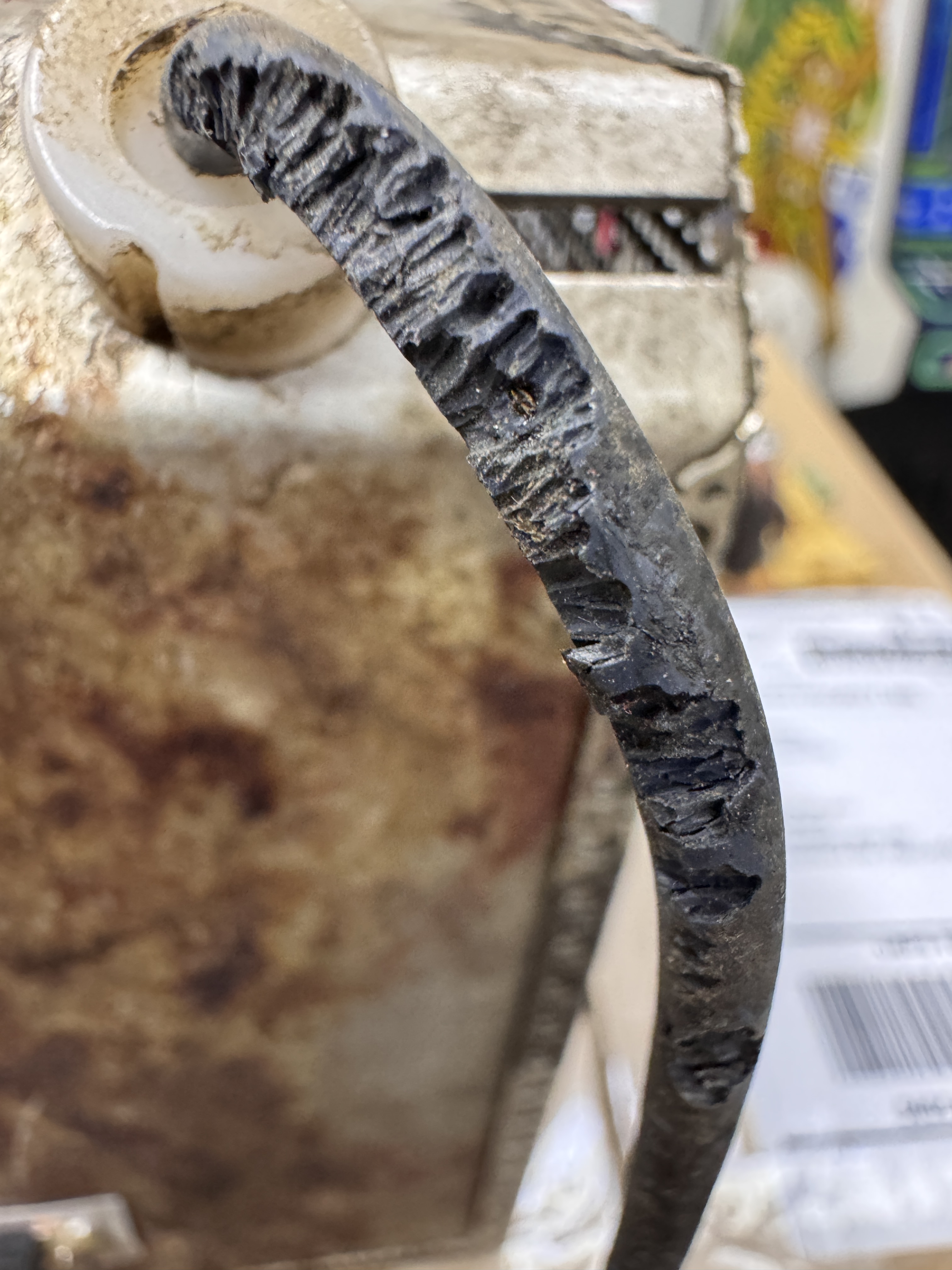
In the HV cage – there had been a grease explosion at some point. I was able to get the HV diode apart. One side was clean – but the board side connection was in pretty bad shape.

This is after the first round of cleanup. I was going to remove the boots and solder the diode in directly, but I kept cleaning the bad one and it had a solid connection under the crud. I used the meter and tested ohms through to the coil and nothing seemed loose inside.

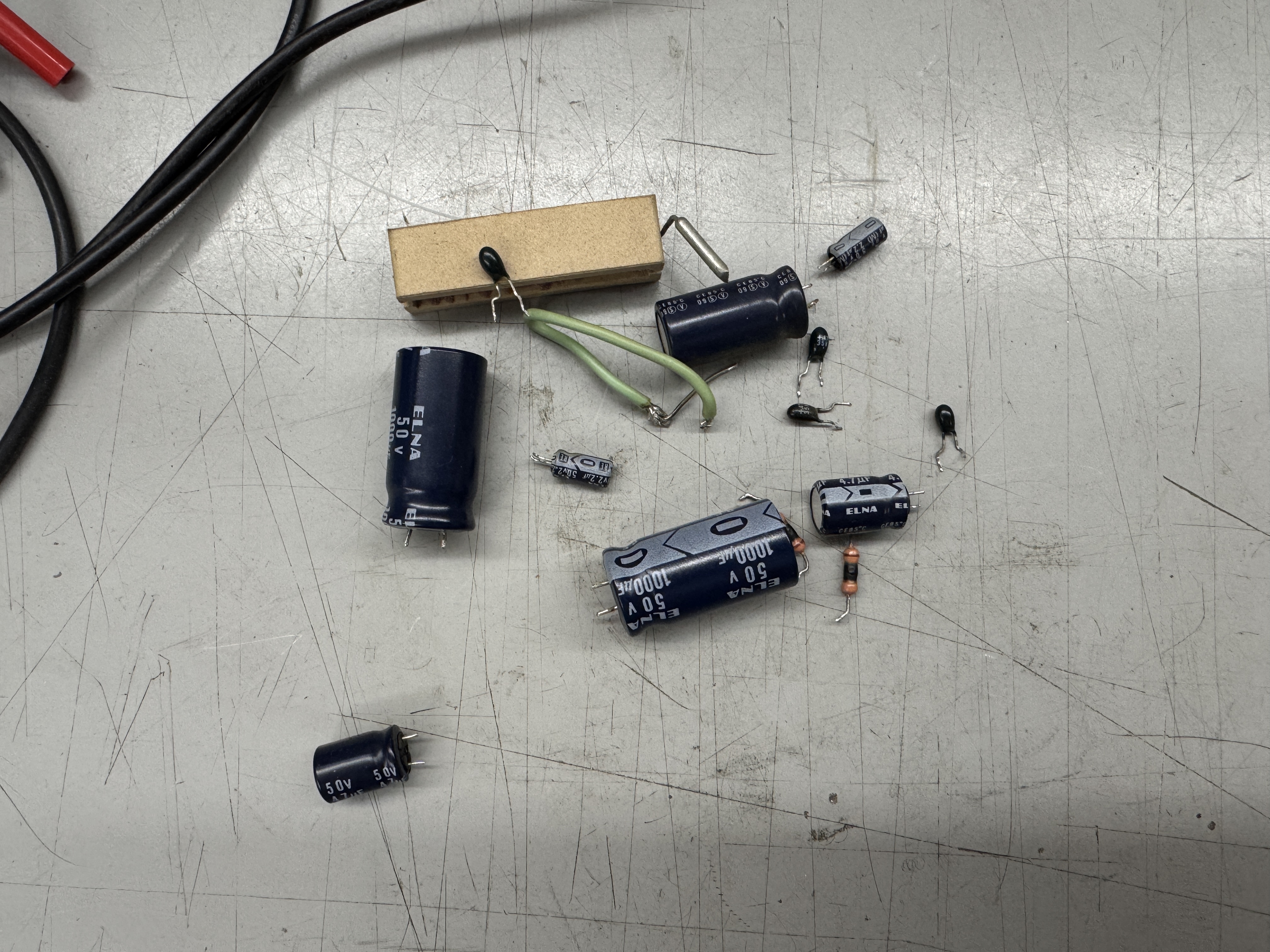
Received a cap kit and a new HV diode. I forgot to get a pic of my replacement. One spring was junk and the other had disintegrated. My solution was a stiff replacement spring from a pen. I curled the leads on the diode to match the pen spring that I trimmed down to about 1/4″ and soldered them to the leads. I put it back in the boots and used a little RTV sealant to secure the boots into position. Since the kit came with a transistor set, I replaced them even though the originals tested good. Testing around the board showed R100 was failing so I removed it and R101 per the Atari service document. 3 of the fuses were the wrong ones – fixed that too. One of the capacitors wasn’t connected. Someone had cut the original on the parts side and then soldered a replacement to the lead sticking up. That solder joint failed. So weird..
I test caps as I take them out AND put them in just to see if there are any bad ones. I couple were out of spec – but nothing too crazy except the one that wasn’t connected at all.
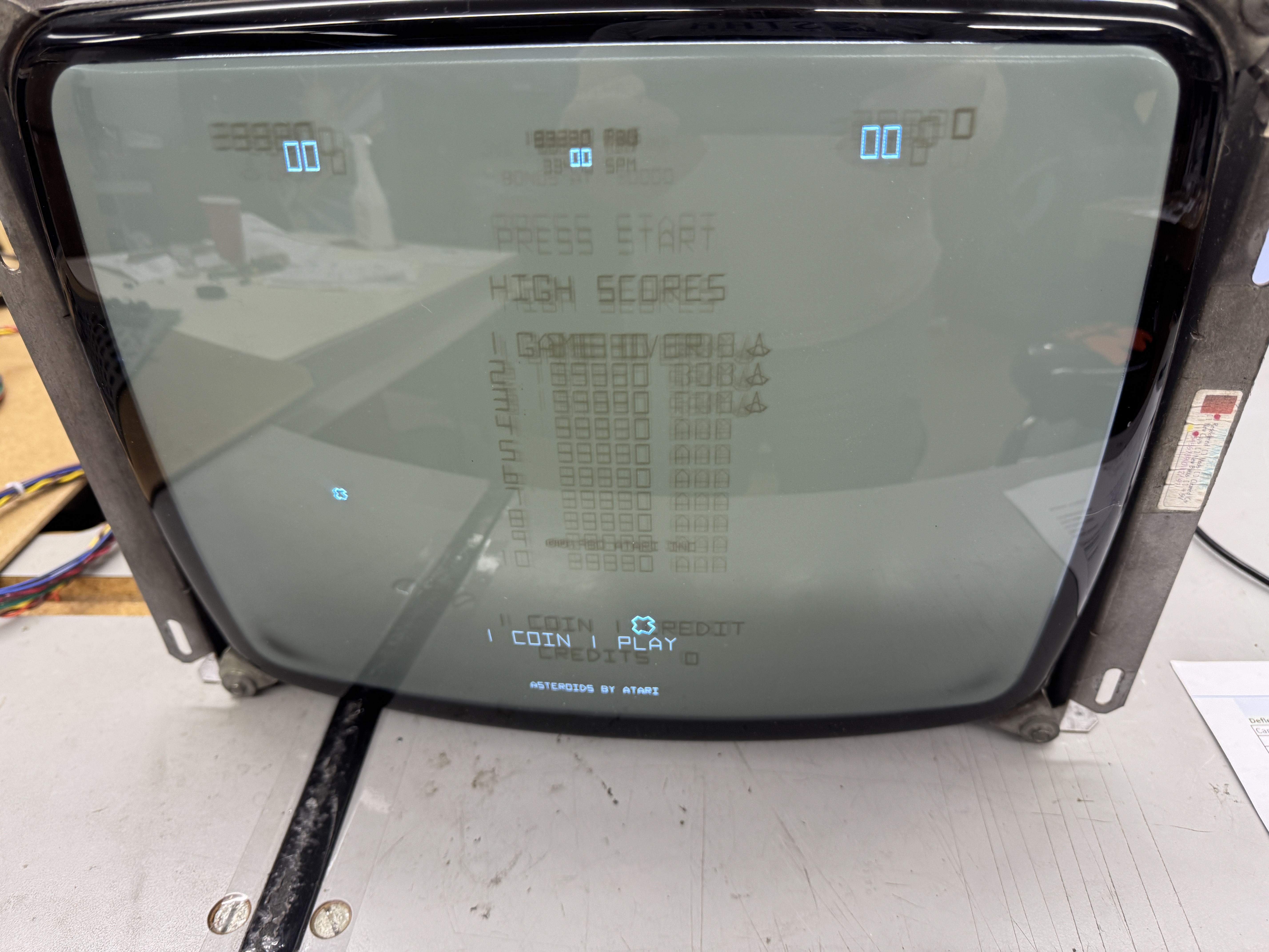
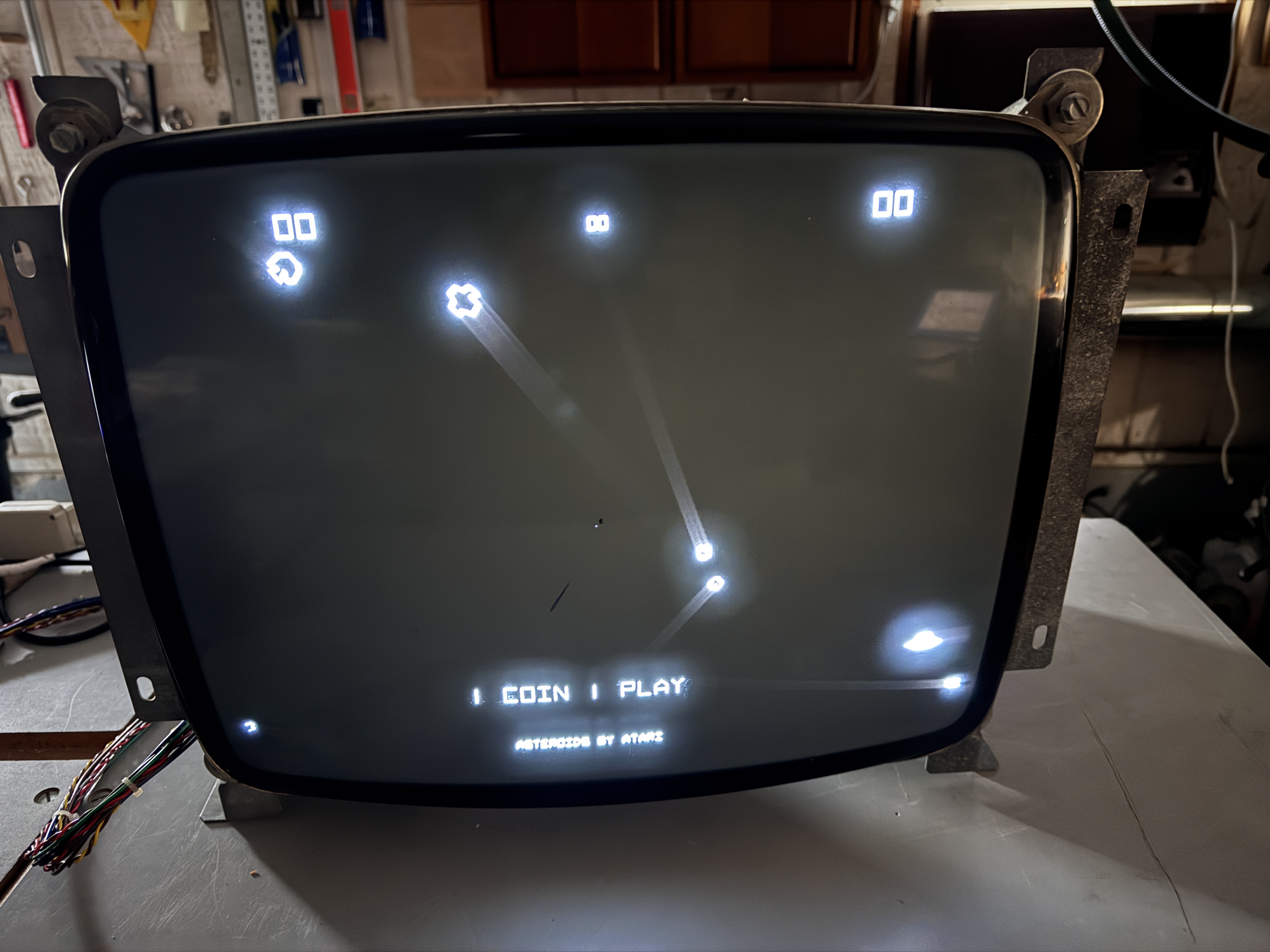
Monitor fired right up! My first vector CRT repair. The picture was jumpy when I first powered it on, Deoxit on the pots cleaned that up. I picked up the B&K HV probe and tested the HV circuit – perfect 14.5KV.
19V2000 – Picked this one up at a friend of a friends house
Came out of an Asteroids Deluxe. Monitor was dim in the center of the screen and brighter at the edges and it had a big blooming issue..
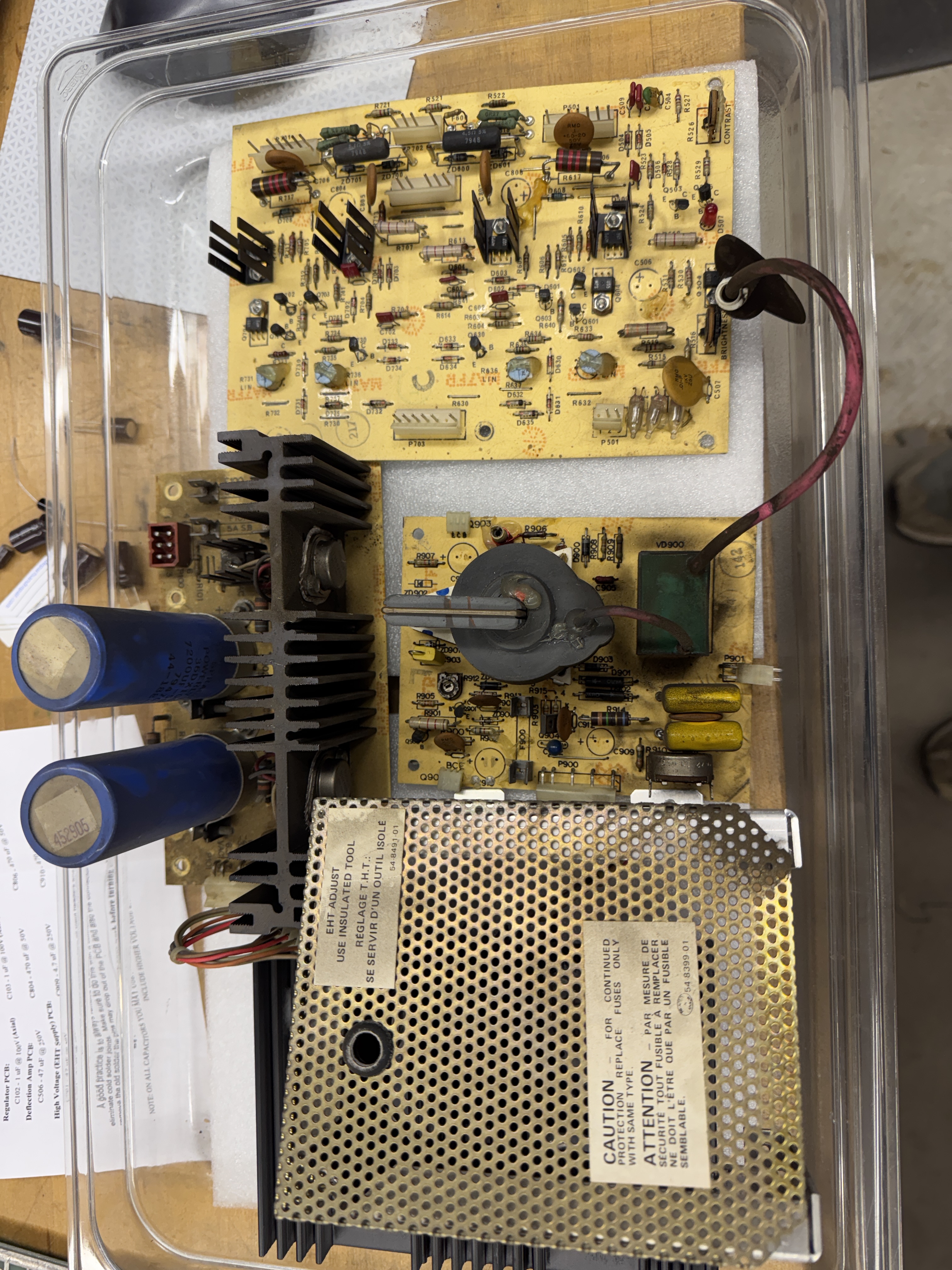
More often than not, recapping, cleaning and reflowing pins on these chassis gets them back into working order.

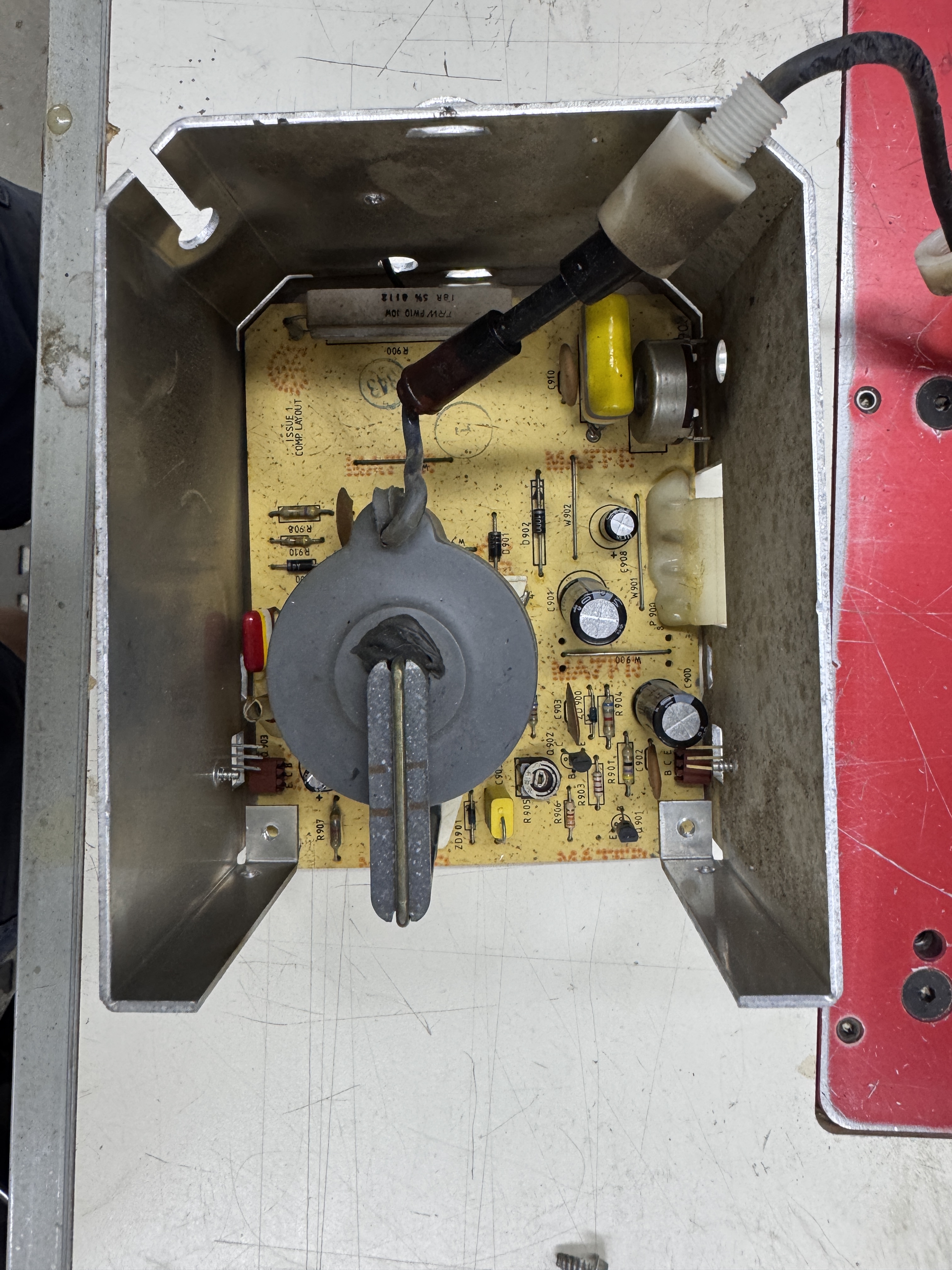
It appeared the blooming was just a loose diode – this was not the case. Once cleaned and rebuilt, the deflection board seemed to work – but I could not get HV to move above 7KV.

Spent a lot of time in the red area trying to determine why there was nothing going on. I’d checked the resistance on HV transformer and all coils matched up vs. a known good one. However I was getting ~50v on P900 pin5 and ~200 on Pin3. Learned a lot about how this all works on this one.
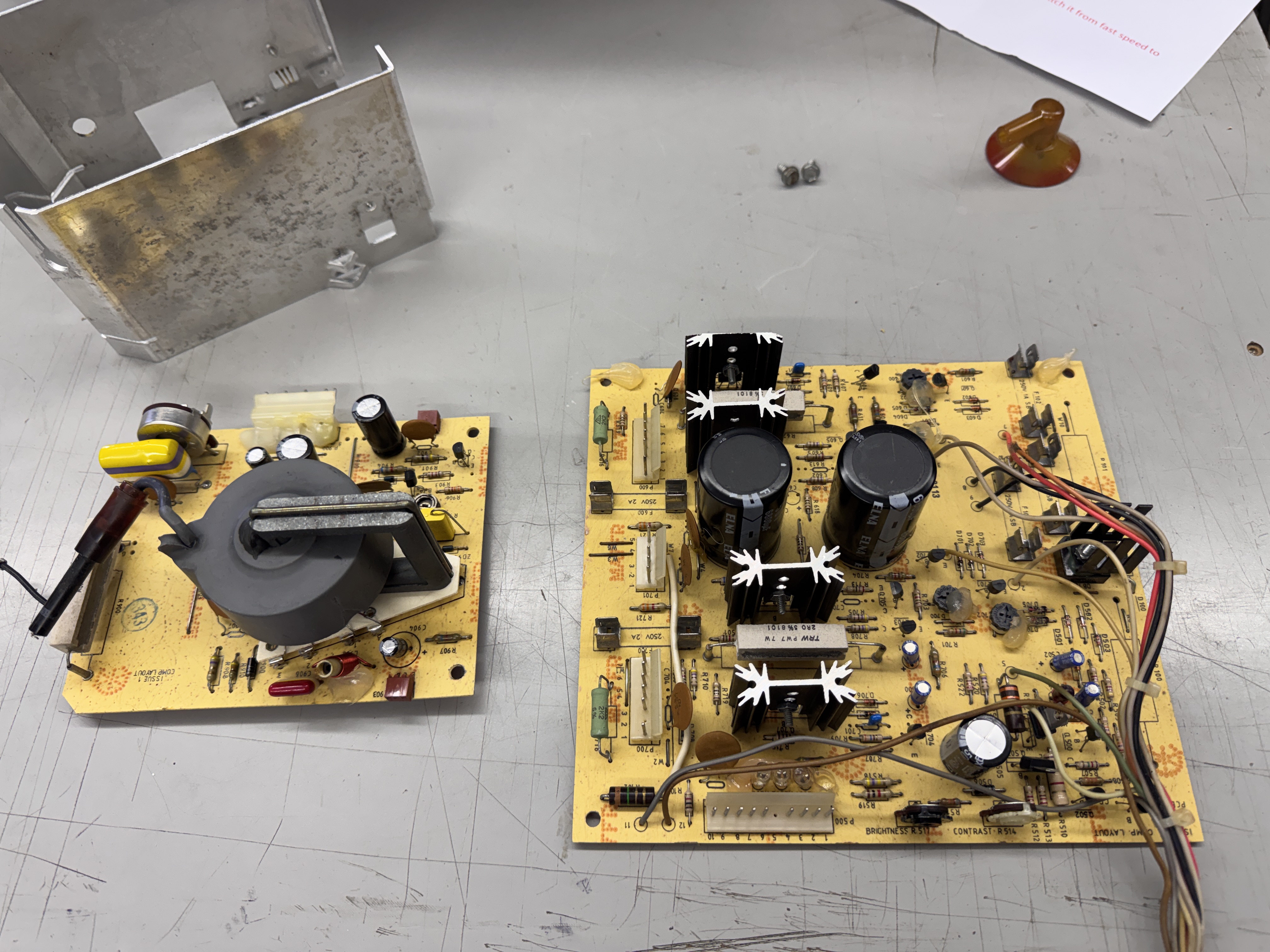
But I had missed seeing this (this is with flash – it was a lot less noticeable) Bad HV transformer – makes perfect sense now.. Swapped one in and the monitor worked. Resistance didn’t seem to matter in this case.
One last item, you could flex the board and it would cut out and the spot killer would come on.. I pushed around the board and it was all along the outer edge.. I removed and reflowed all the wires and it slowly got better and more localized as things got reflowed. This particular board has some surface oxidation on everything.
The last little spot was here.

This did not immediately break. I reflowed the pins for all of these diodes – tried the board and the spot killer came on and stayed on, good! Poked them all again and D502 finally broke apart.
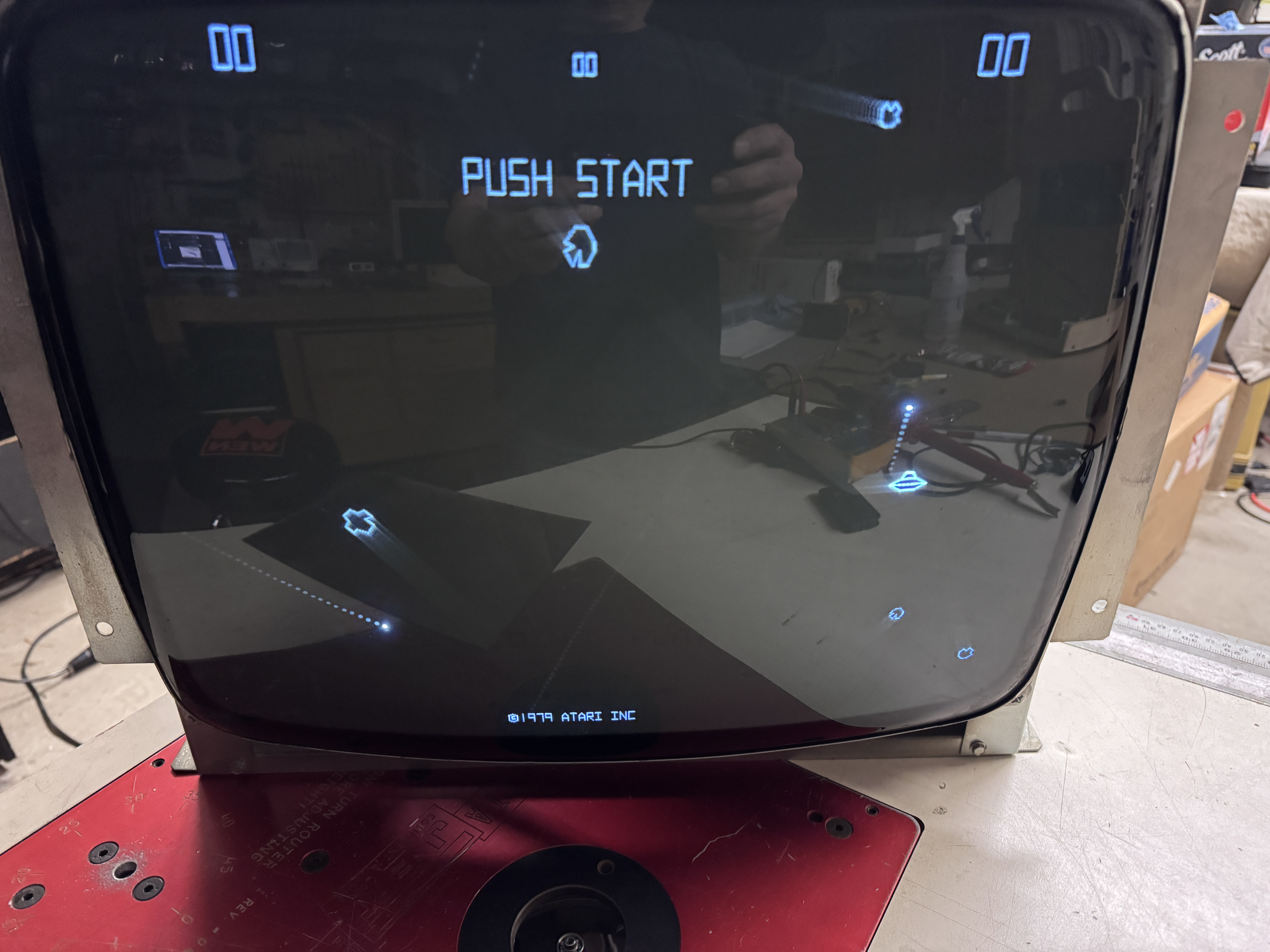
Chassis works!
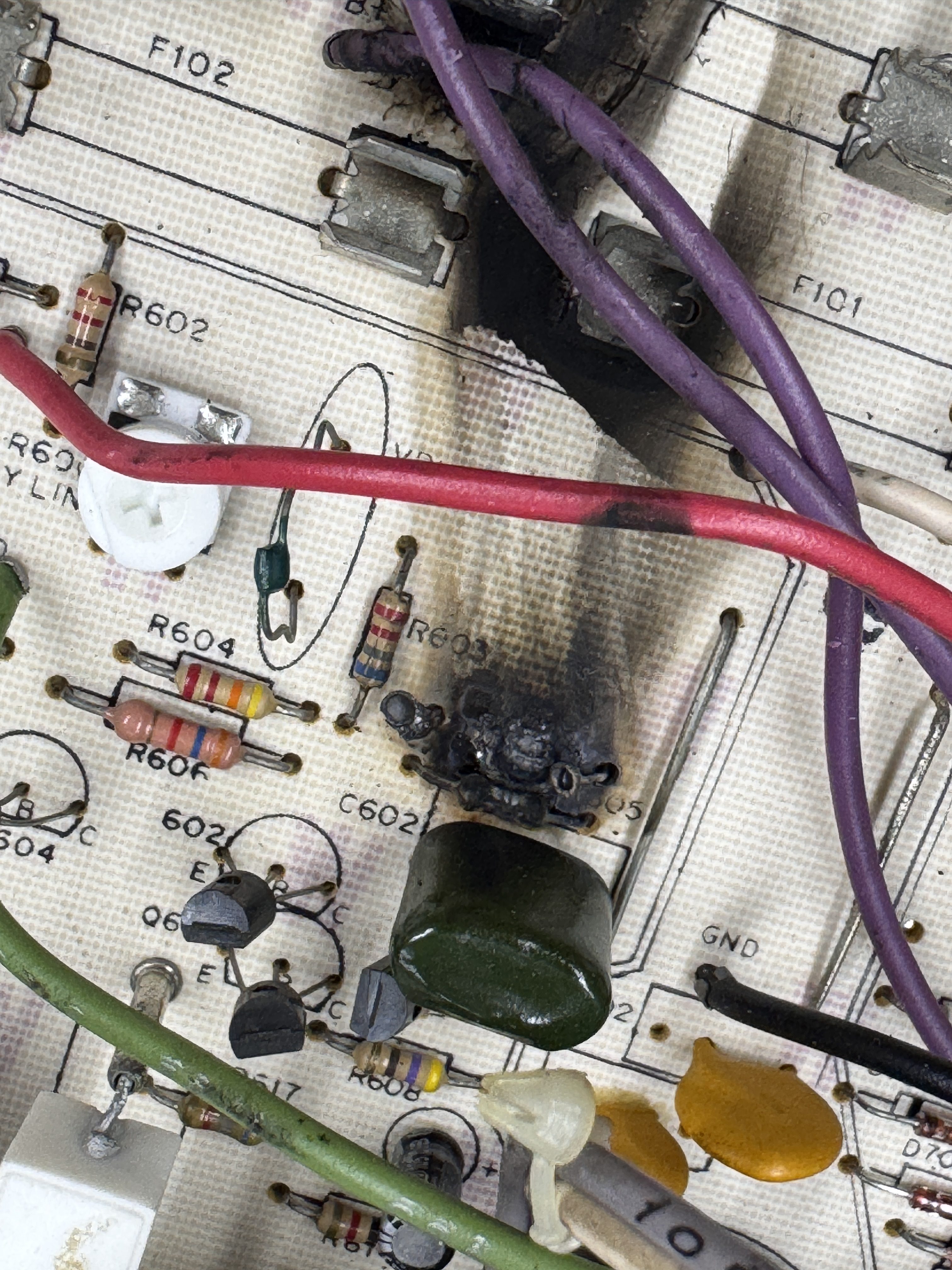
19V2000 #3 – Monitor in from an operator

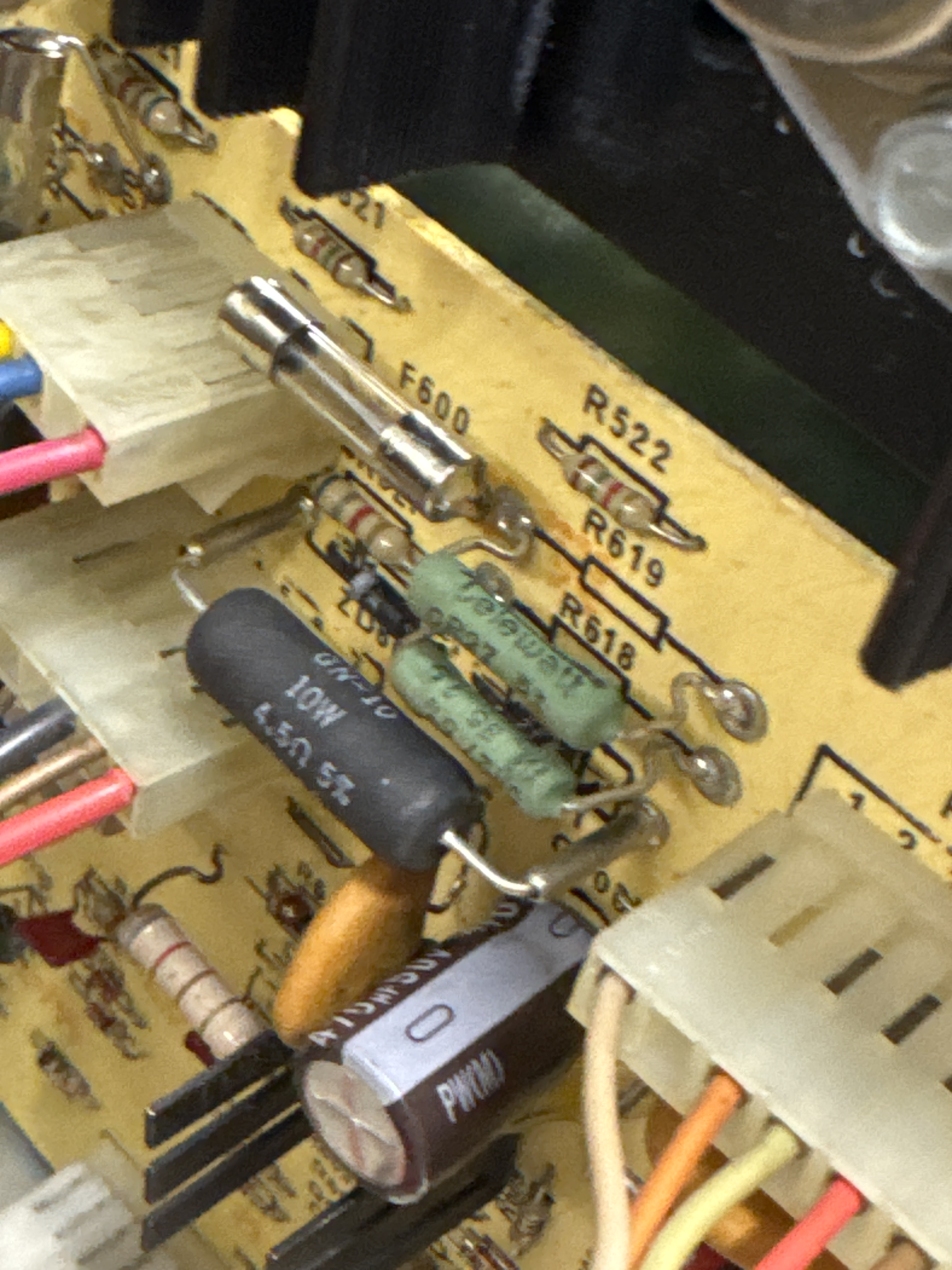
F600 had finally blown at some point, but many of these burned up.


After washing, a fiberglass pen does a good job of removing all the soot marks and cleaned up the mess as good as it can get.

All of these were replaced plus the two bottlecaps Q608, Q609

Monitor works!
G05-801 #4 – Rebuild for a buddy

This turned out to be a really nice monitor. Buddy picked up a nice early Asteroids cabinet. Spotkiller was on. It was all original. Pulled it all apart and recapped, re-bedded all of the bottlecap transistors and checked all of the usual components. Diodes, transistors and power resistors. The spot killer LED was very dim, I replace it while I had it all apart.

It was actually dirtier than it looks and I pretty much always wash monitor chassis. Cleaned up really nice. Once that was all done..
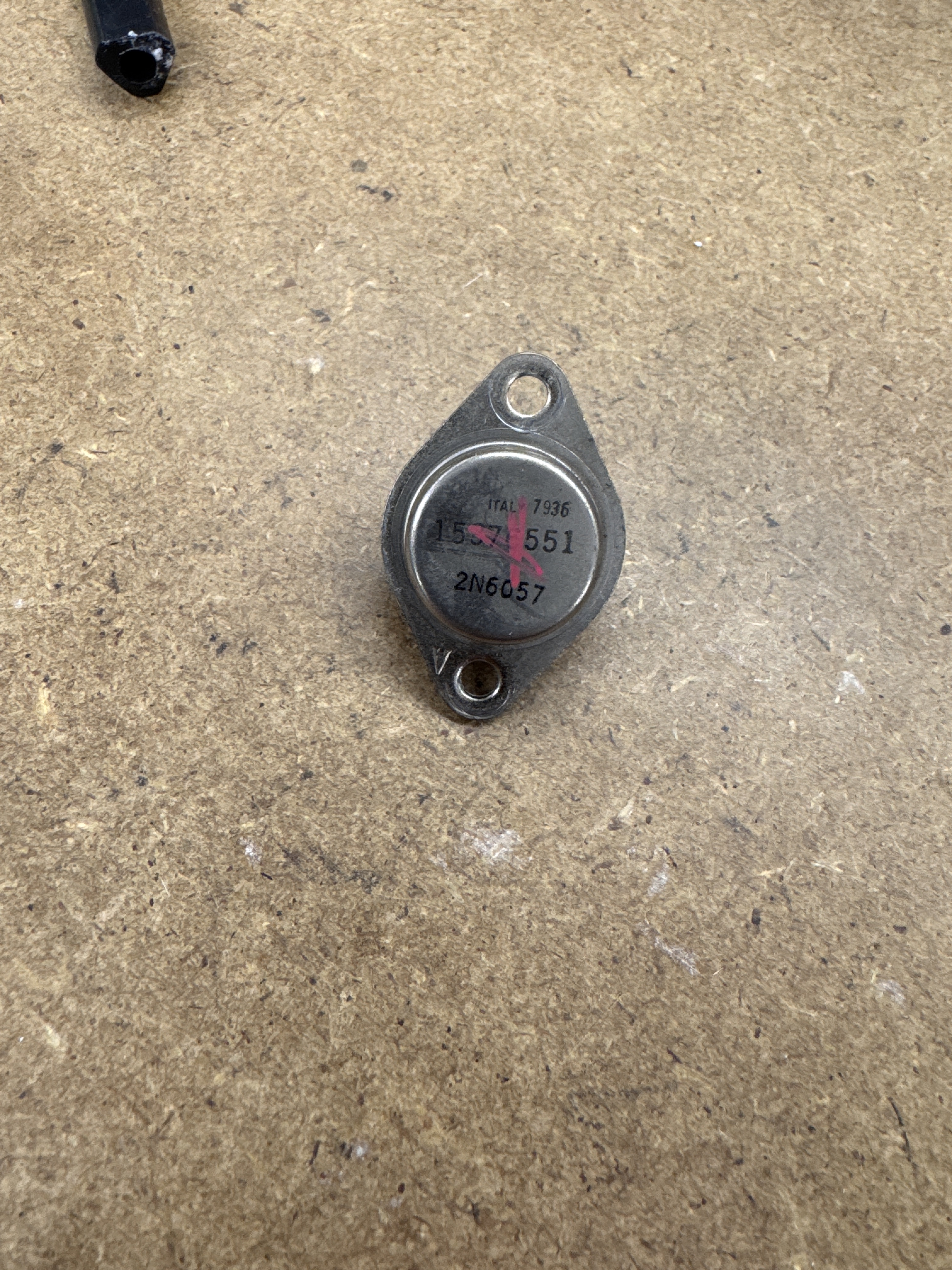
This guy on the power supply board was bad.. Not a common part number for me to have – but I had one! That got the power going, but still no deflection..
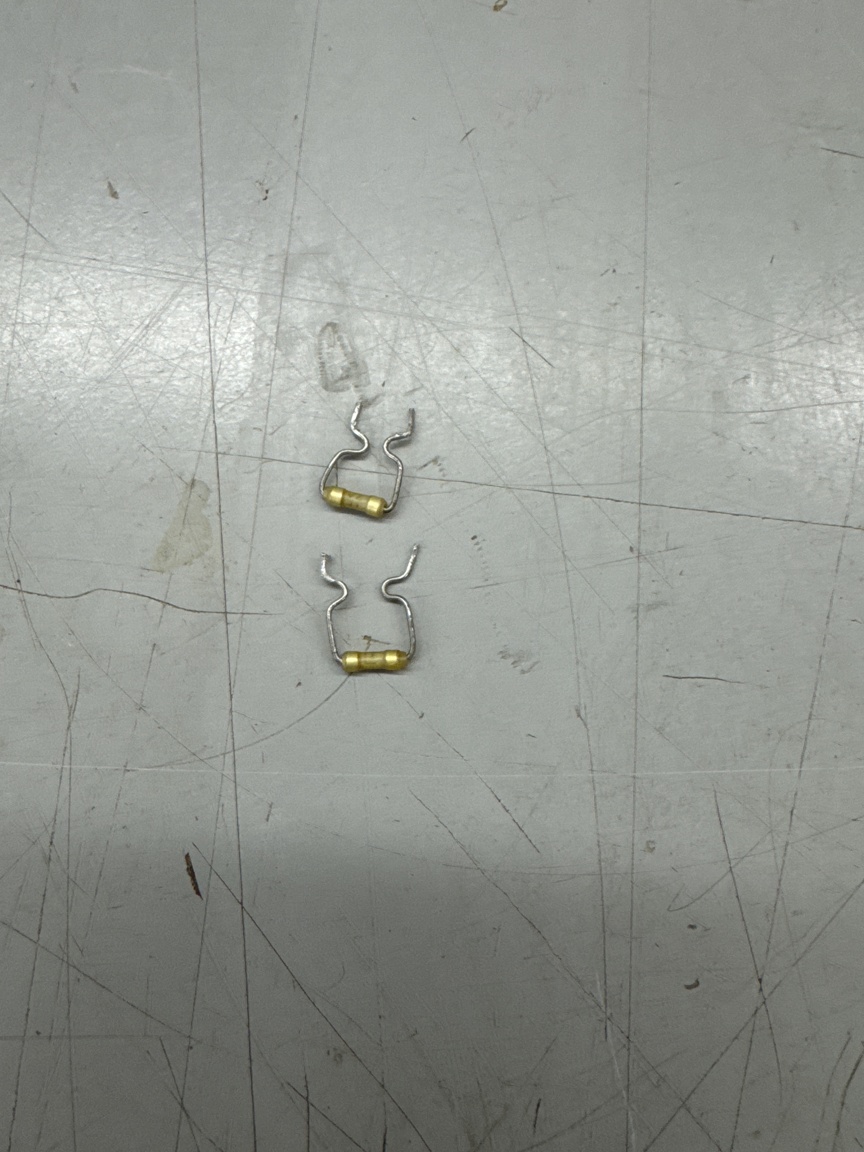
Determined these ‘pico fuses’ were blown.. F600/F700. Did not have any, but was able to solder some legs onto standard fuses and use them in their place. We can replace with pico fuses later.
Chassis works!
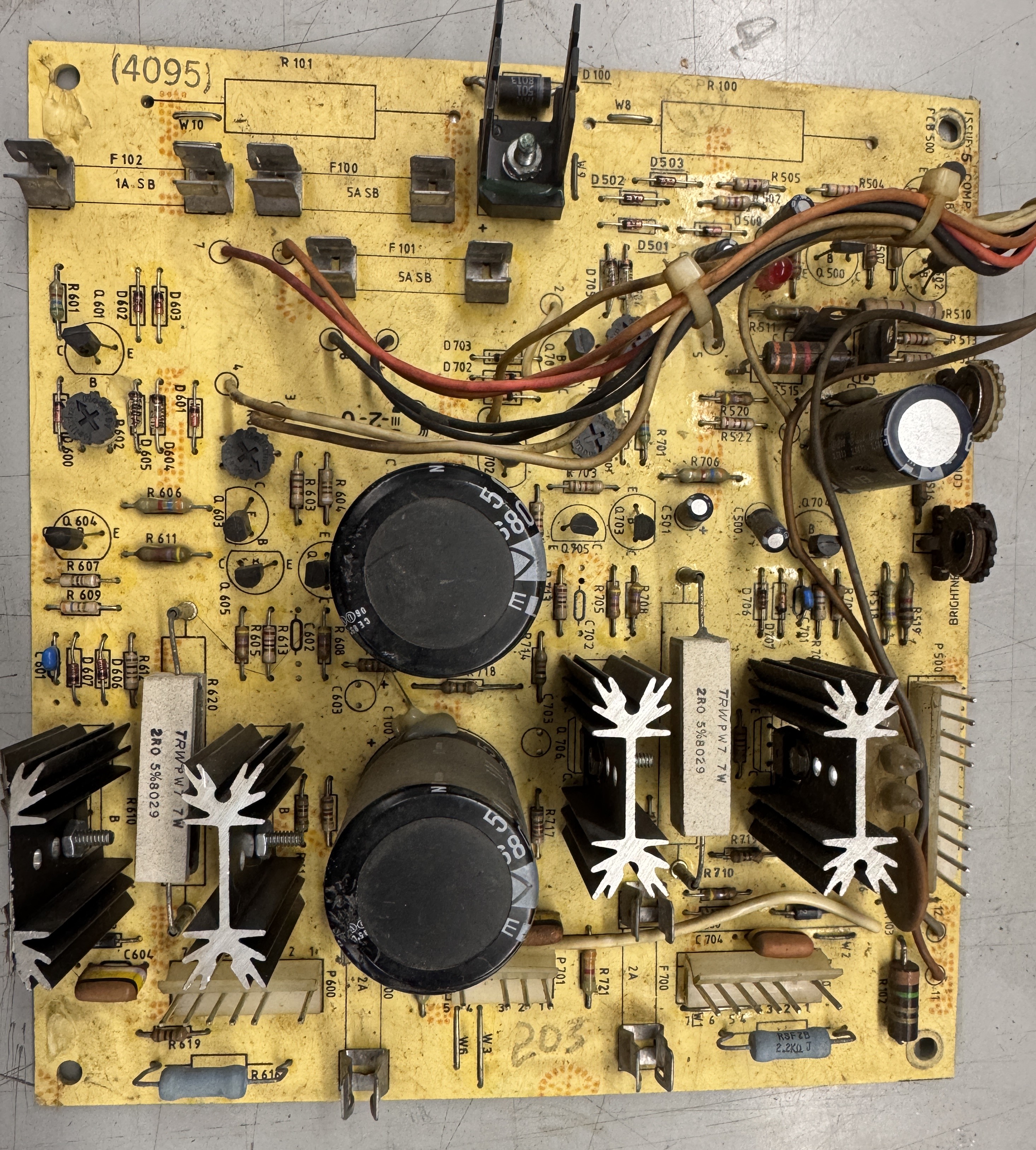
Chassis #5 – 19V2000 Repair
Symptoms:
Reported to have screen collapse and drift.
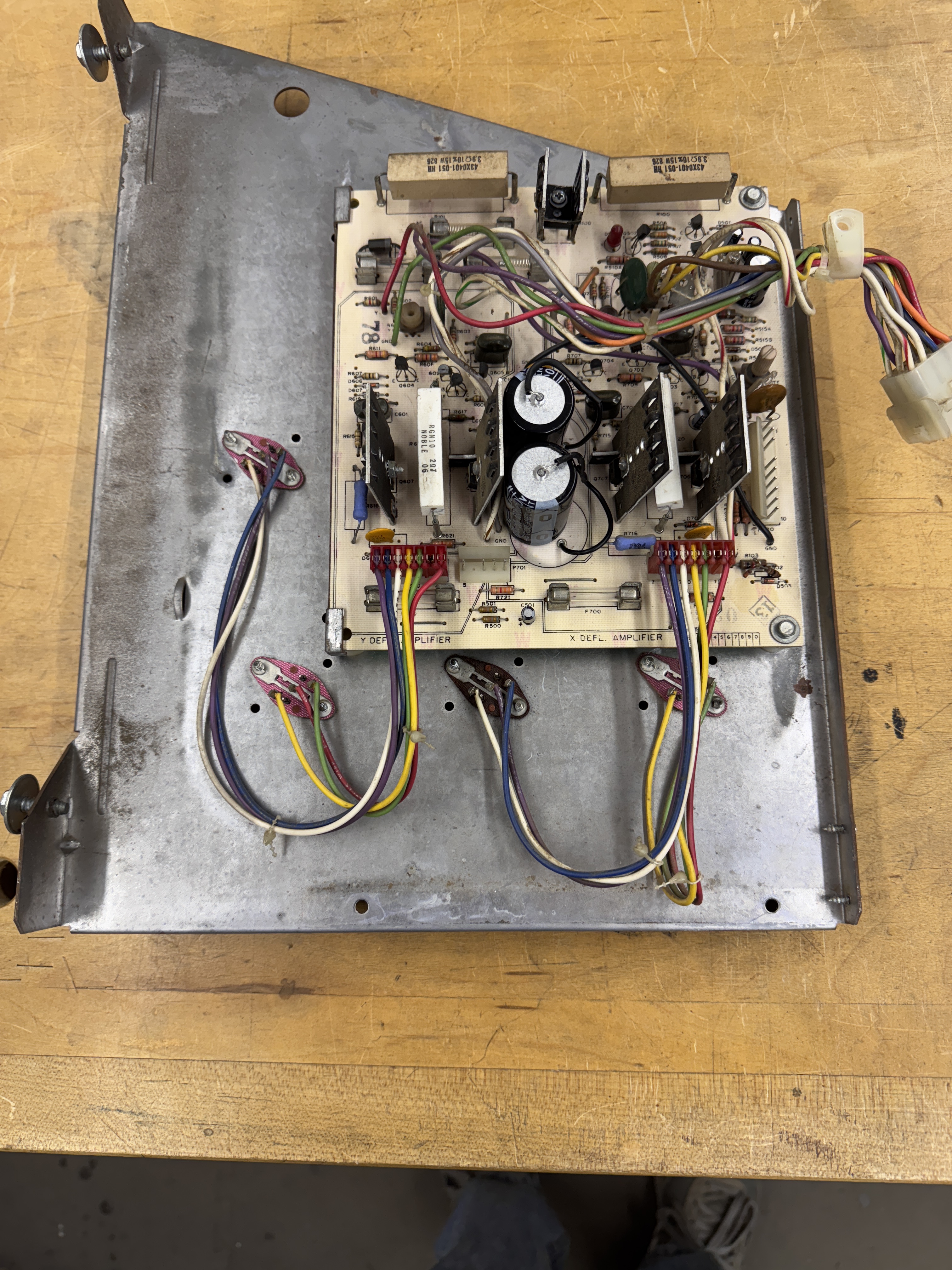
Received the side with the bottlecaps and the HV unit (not shown)
Whenever someone sends me a monitor and says ‘it doesn’t work’ I do not connect anything to so that I can’t make things worse!
I go through all of my standard steps to make it operational:
- Take apart
- Rebed bottlecaps with Silpads
- Wash (more often than not)
- Reflow connections
- Make any mods
- Removed power resistors
- Replaced adjustment pots
Then I bring it up in stages to make sure nothing pops. All good. Ran for 3 hours.
Chassis works!
Chassis #6 – G05-802 Repair
This chassis was sent in as not working. It looked as though it had not ever been worked on.. First I removed all the old caps, fuses, etc. Took the HV cage apart and everything got washed.
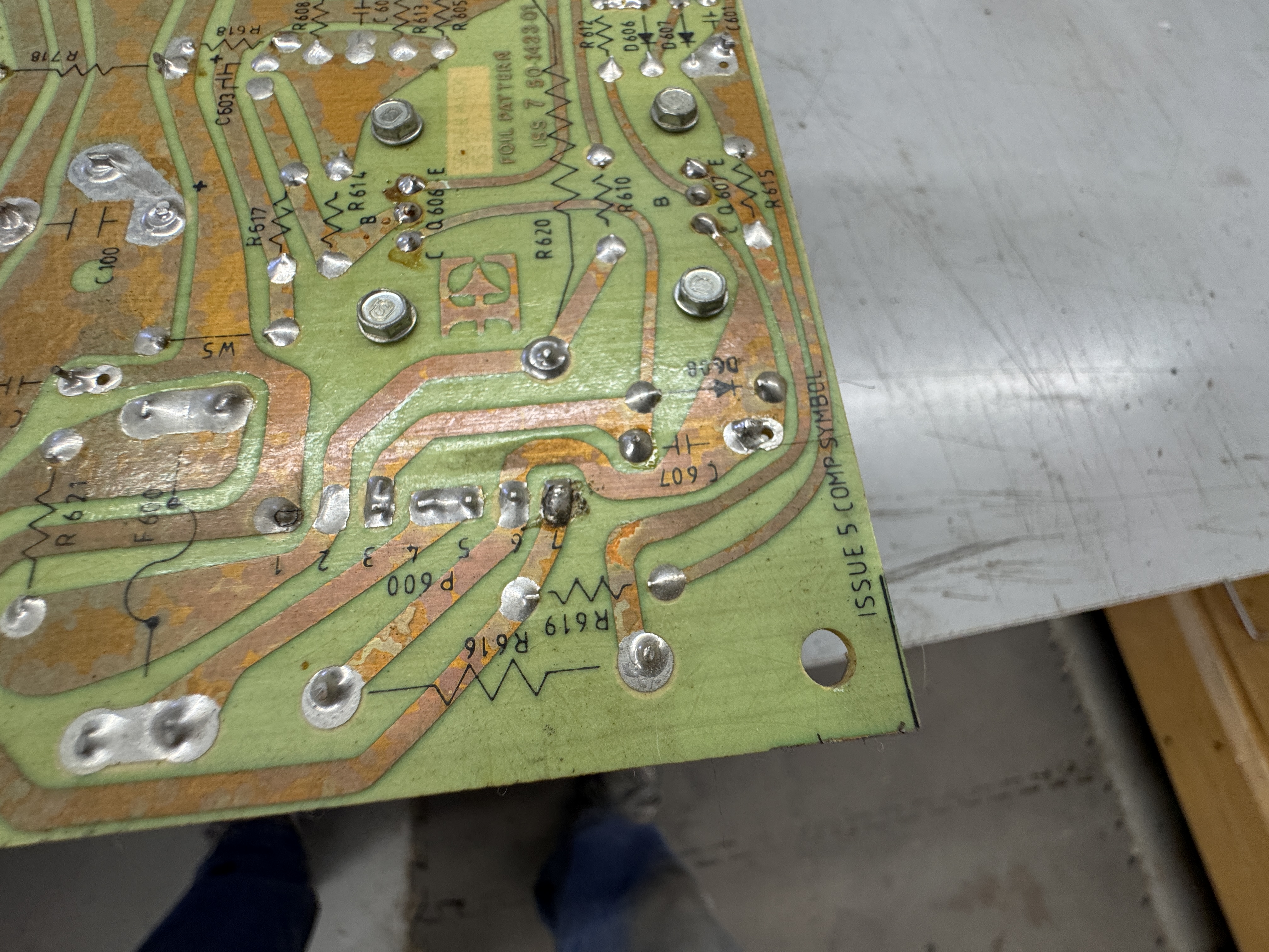

During inspection – cold solder joints at the headers (pin1 on left, pin10 on right)
After recap and reflow of the headers, I rebed the bottlecap transistors using SILPADs and test and tighten the sockets.. Two of the bottlecaps were bad. Once all checked for other issues and reassembled.

Chassis works!
Chassis #7 – V2000 Chassis only Repair
Received a V2000 chassis and HV cage. I always test the HV first (when possible). If the HV transformer has failed then I’d stop here. They are not available. This HV unit worked – it just needed to be cleaned.
This chassis had been rebuilt a few years ago – but had a significant failure. It came in without the chassis frame – but I’m 95% certain this failure was caused by a failed frame transistor. I’ll make sure the customer checks them before putting the monitor back together.
Another item of interest – this cap was pulled clean of the solder (cracked joint)
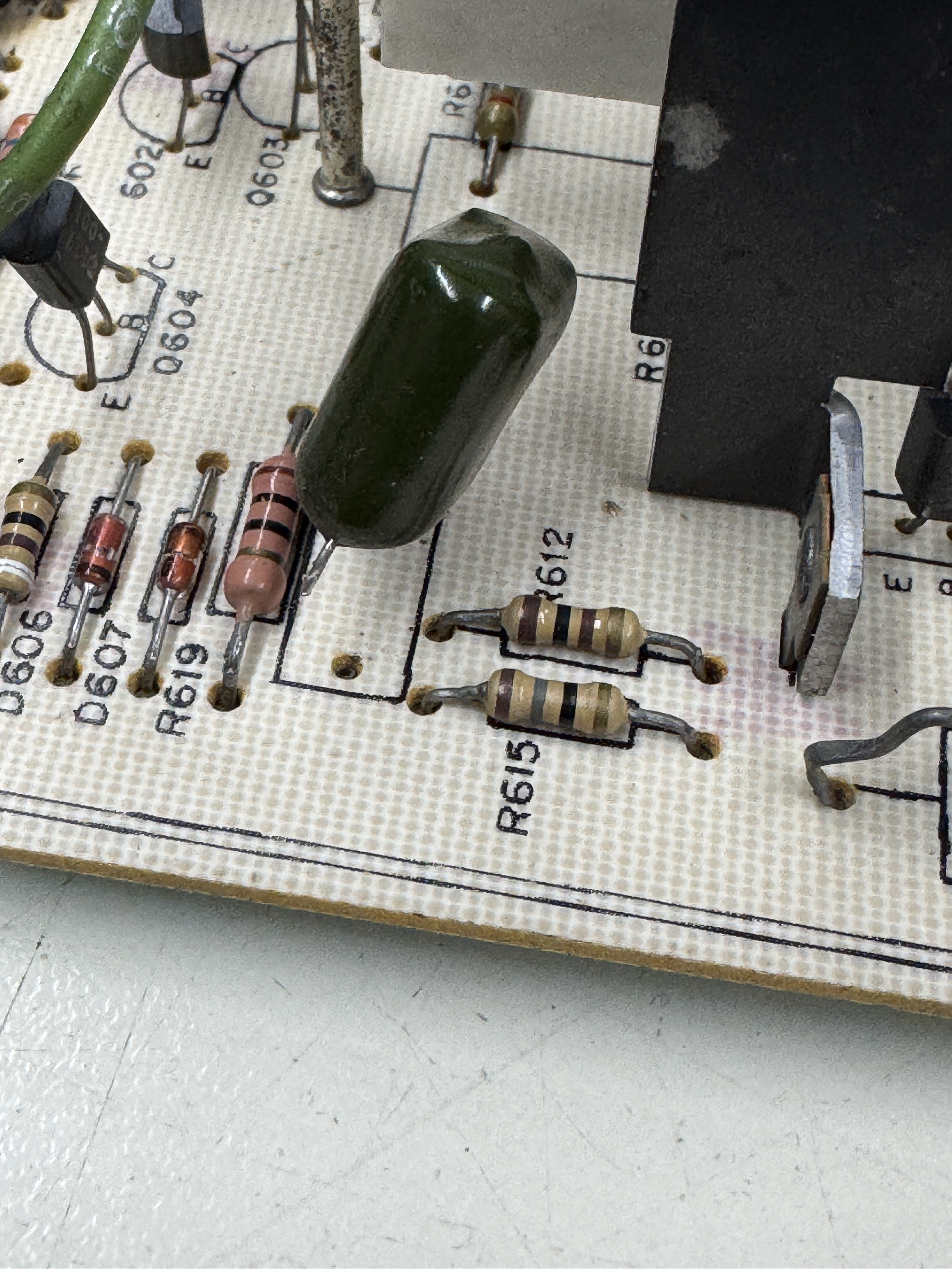
There were a number of components replaced as a result of all of this:
- F600
- Q605, Q606
- R605, 613, 618
The HV and chassis got washed

Chassis works!
Chassis #8 – V2000 Chassis Repair
This one came in and needed a lot of work. Items of note:
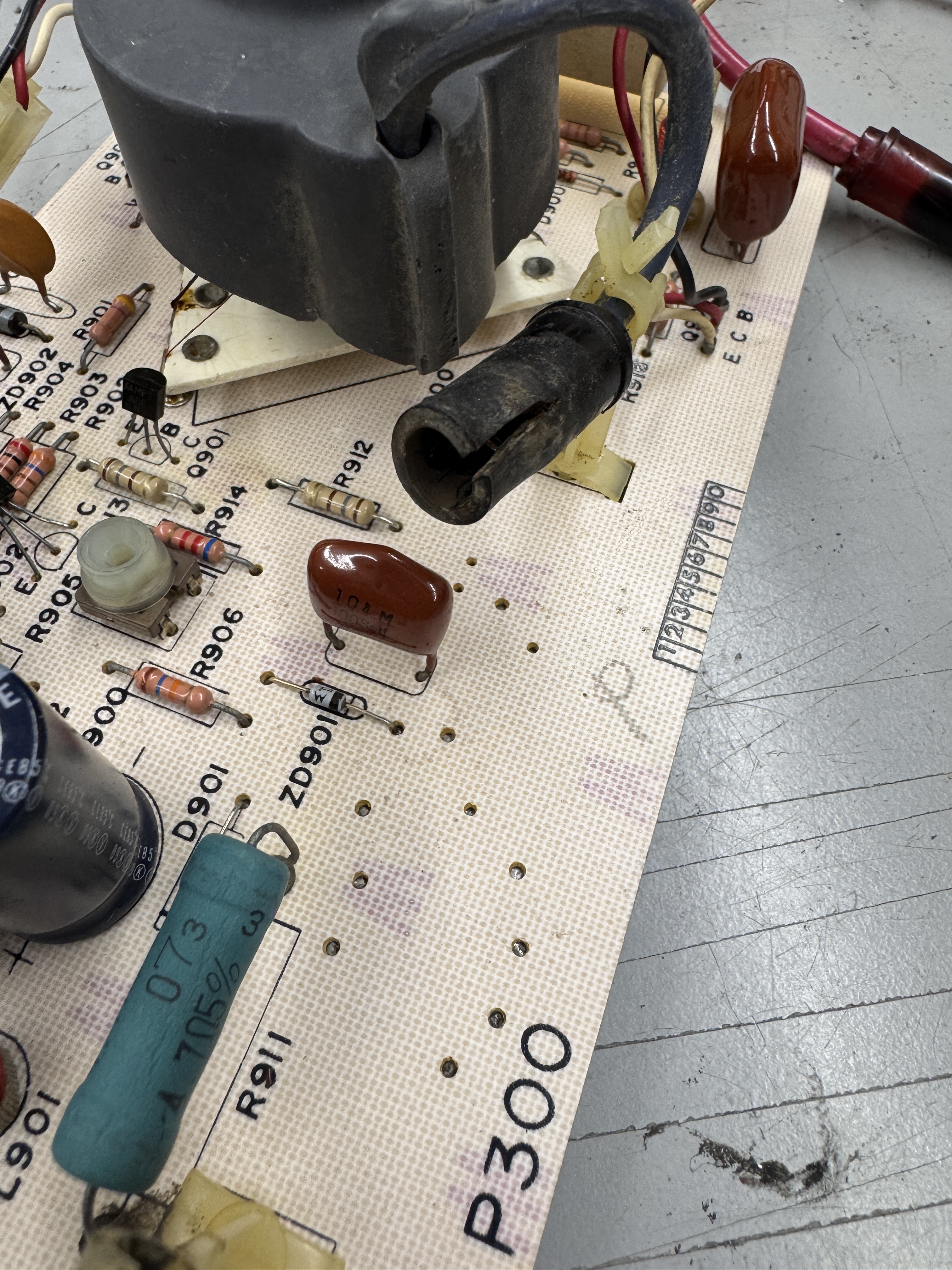
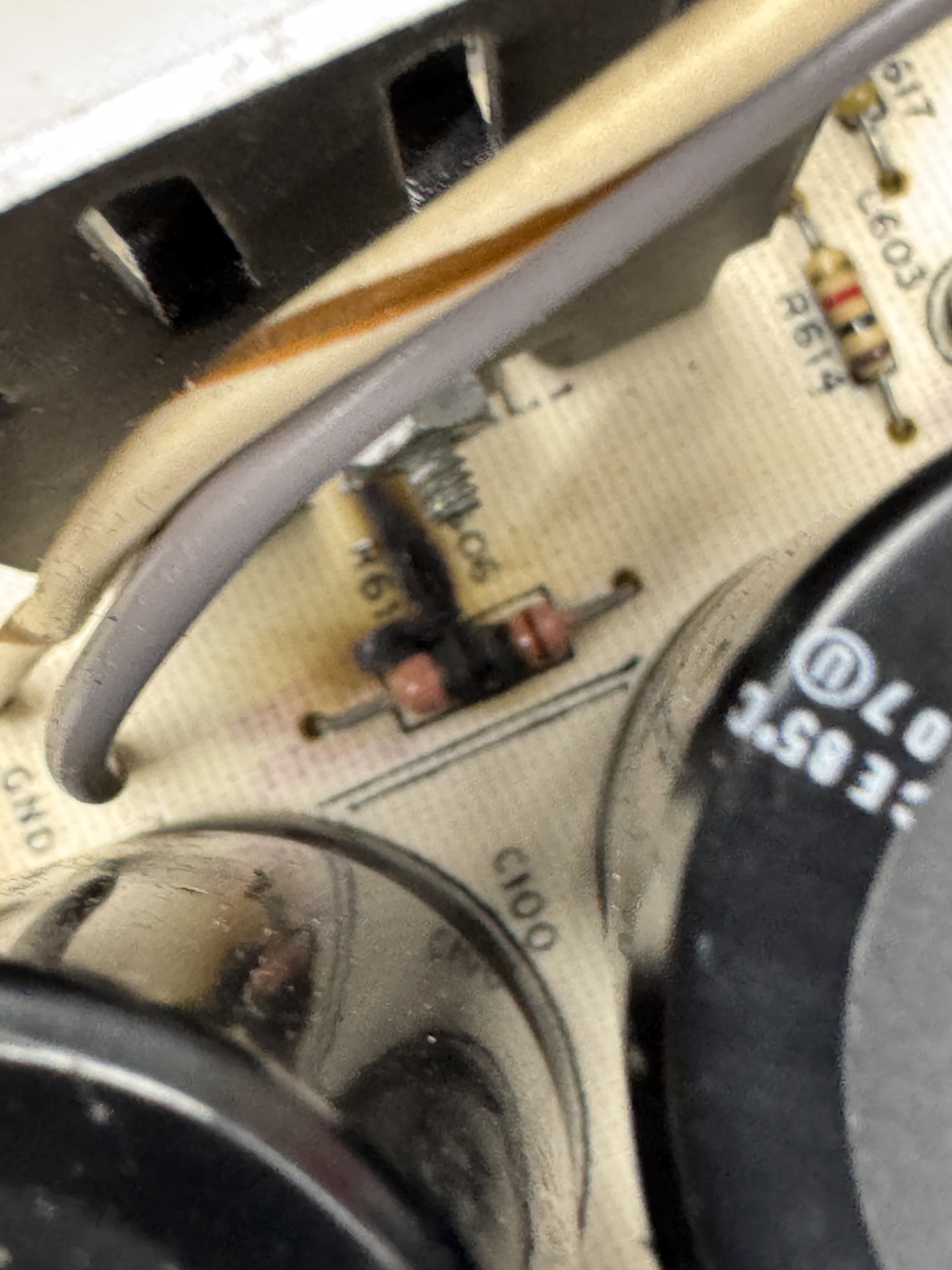
The HV diode and the HV cage all needed to be cleaned. The boot had a crack.. I used adhesive lined heat shrink tubing to pull it back together and close the gap. R912 and R913 were burned up (but still good surprisingly)
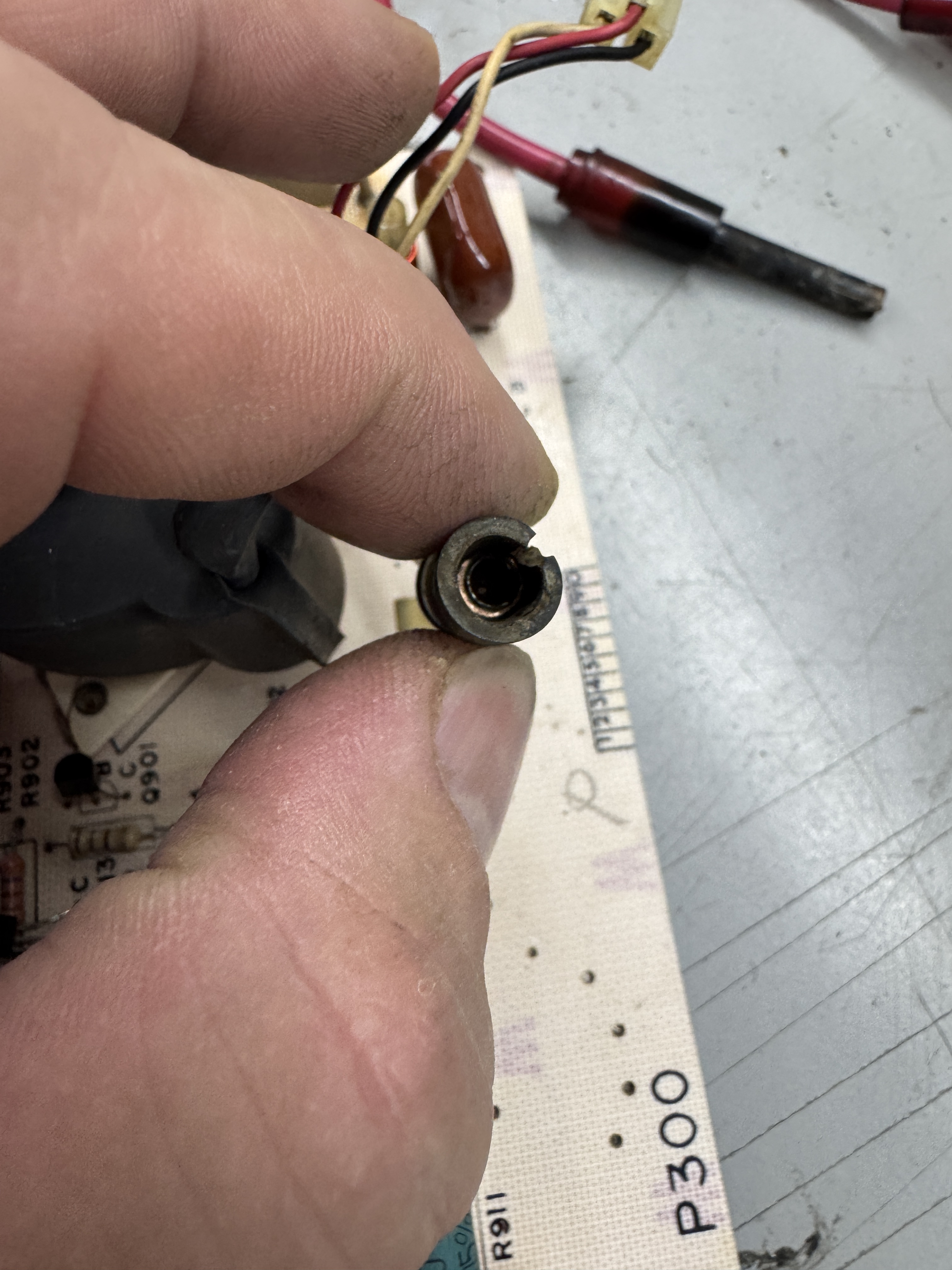
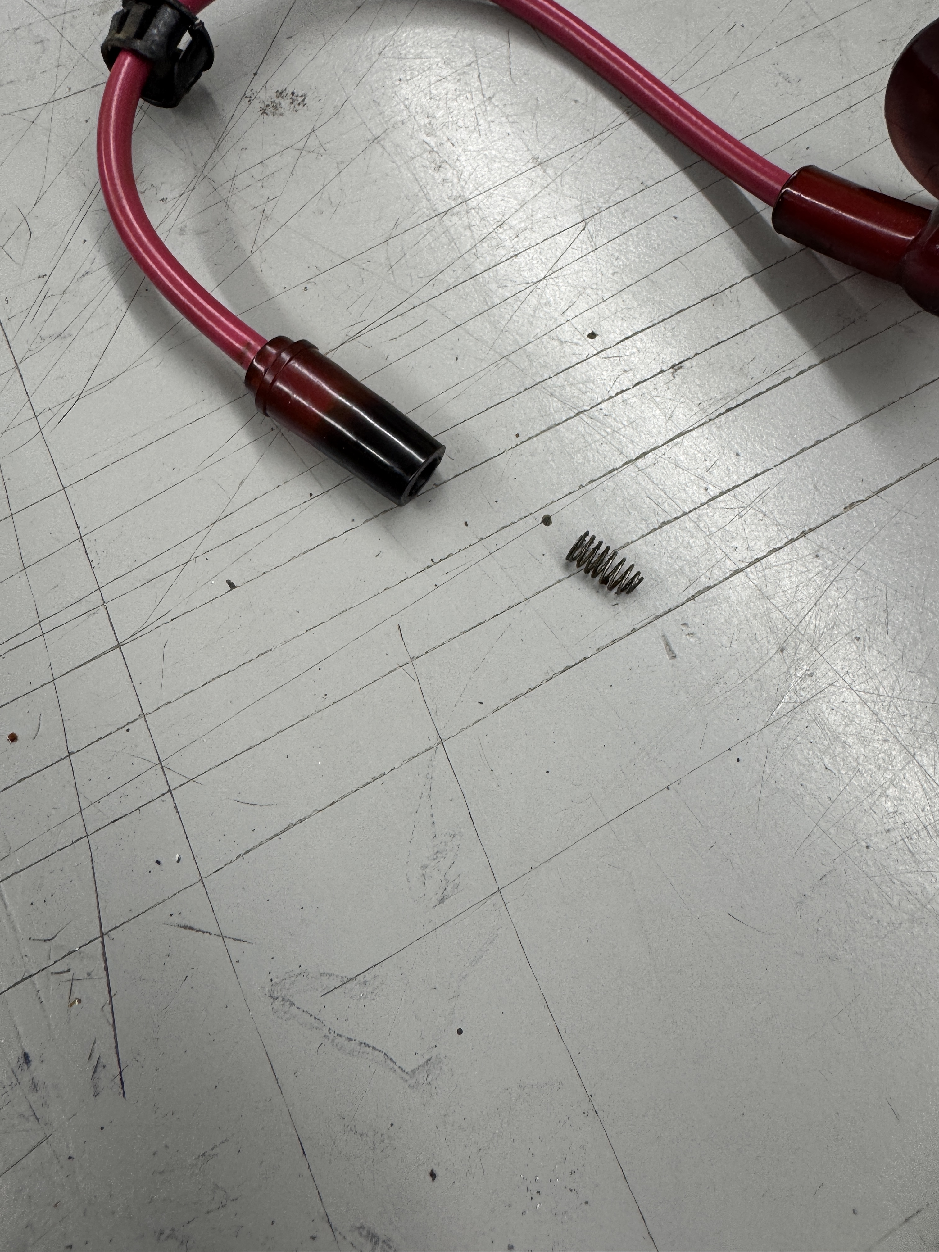
On the HV transformer side, the contact and spring were all corroded. The tube side was in nice shape. I cleaned out the bad side, polished up the contact area with a Dremel bit and actually had an extra spring contact. Testing showed the HV transformer worked – great!


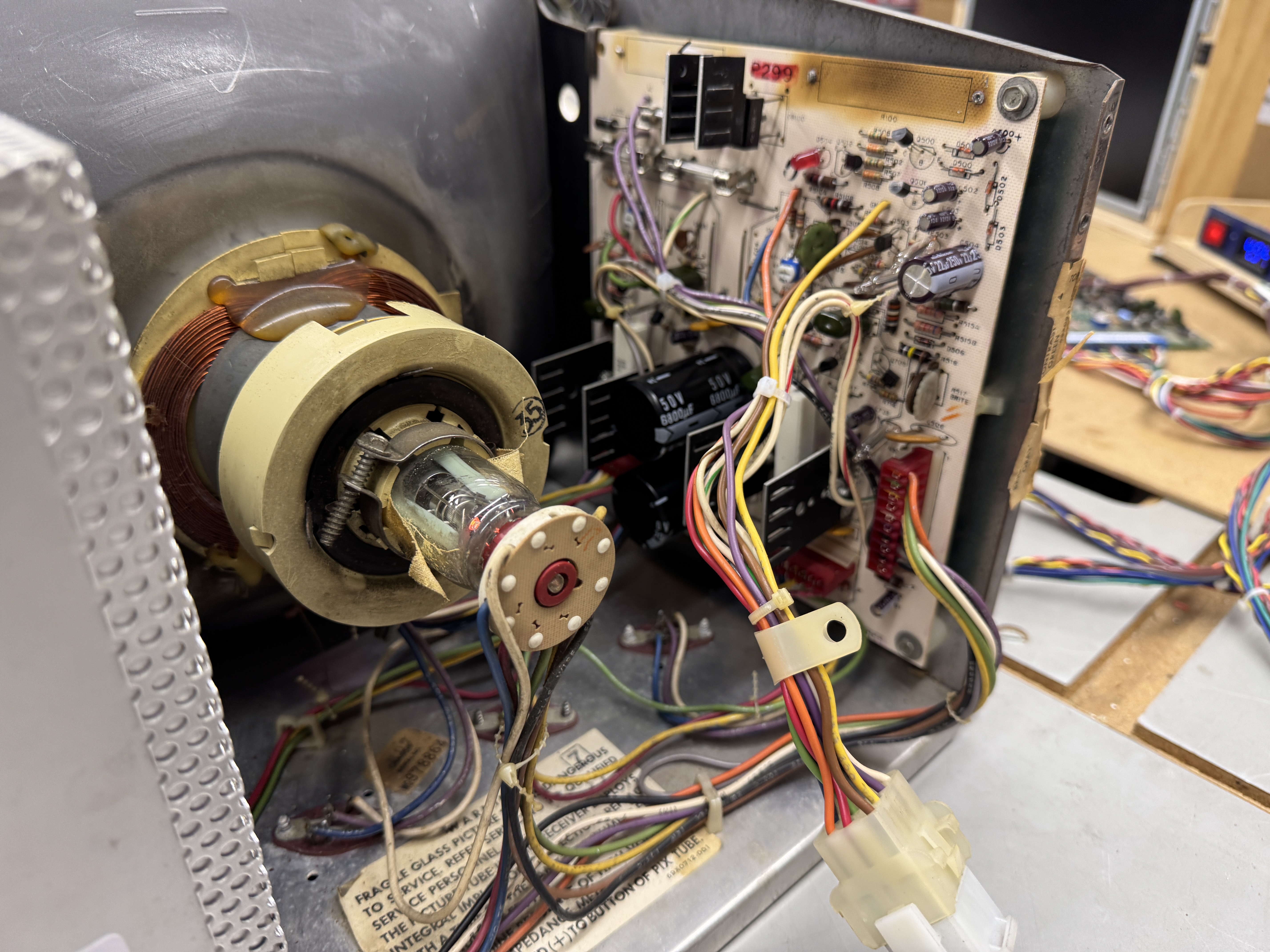
The chassis itself was a bit of a mess and hacked up a bit. It got recapped and cleaned up. The power resistor got removed. and the posts came out too. This chassis came complete. I rebed all of the power transistors, tightened the connections, etc.

Monitor works!
The debris..
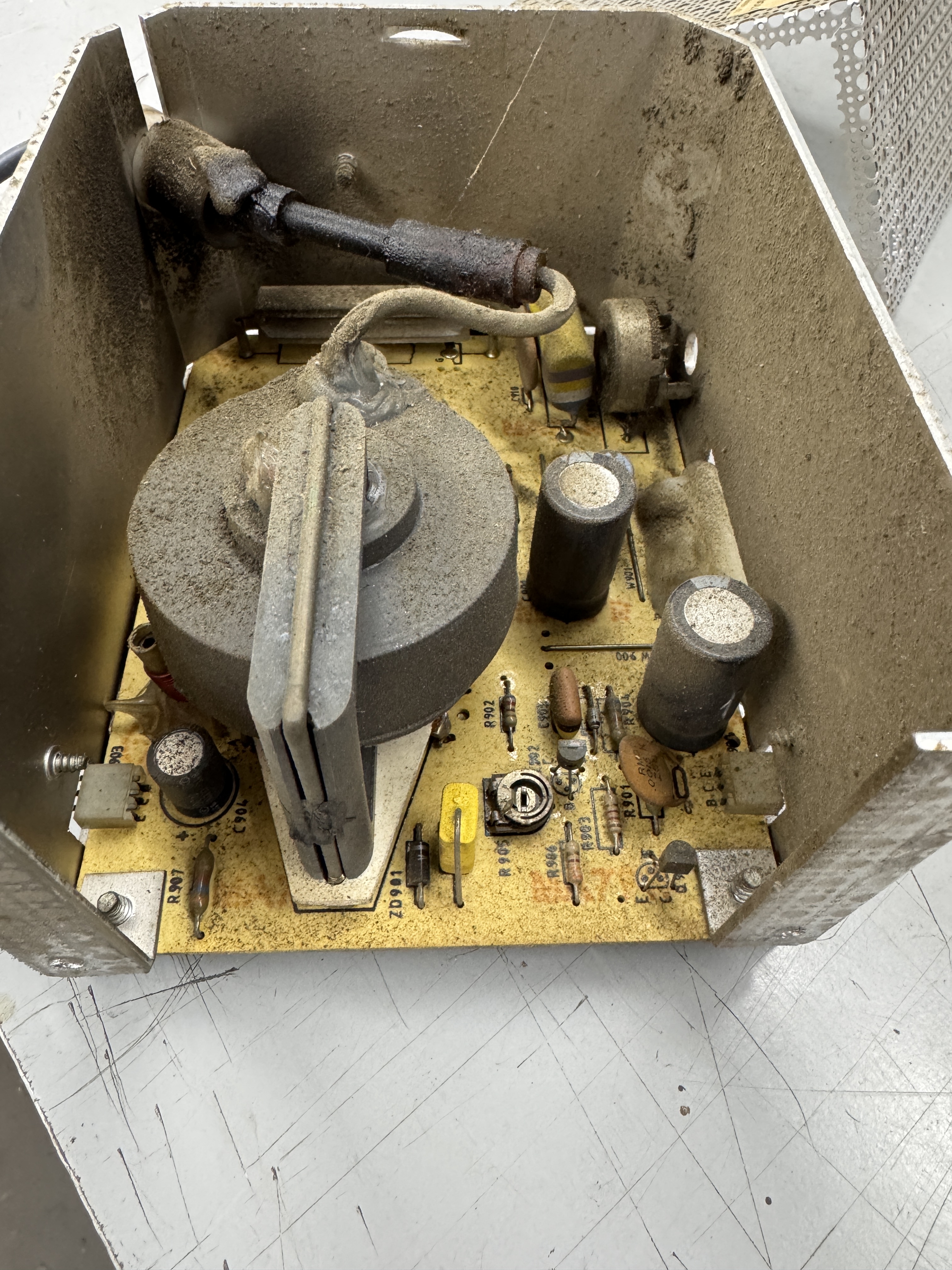
Chassis #9 – G05-802 Chassis Repair
Chassis was sent in stating that it had been worked on, ran for 4 hours and then had a failure where it was too bright and could not be adjusted.
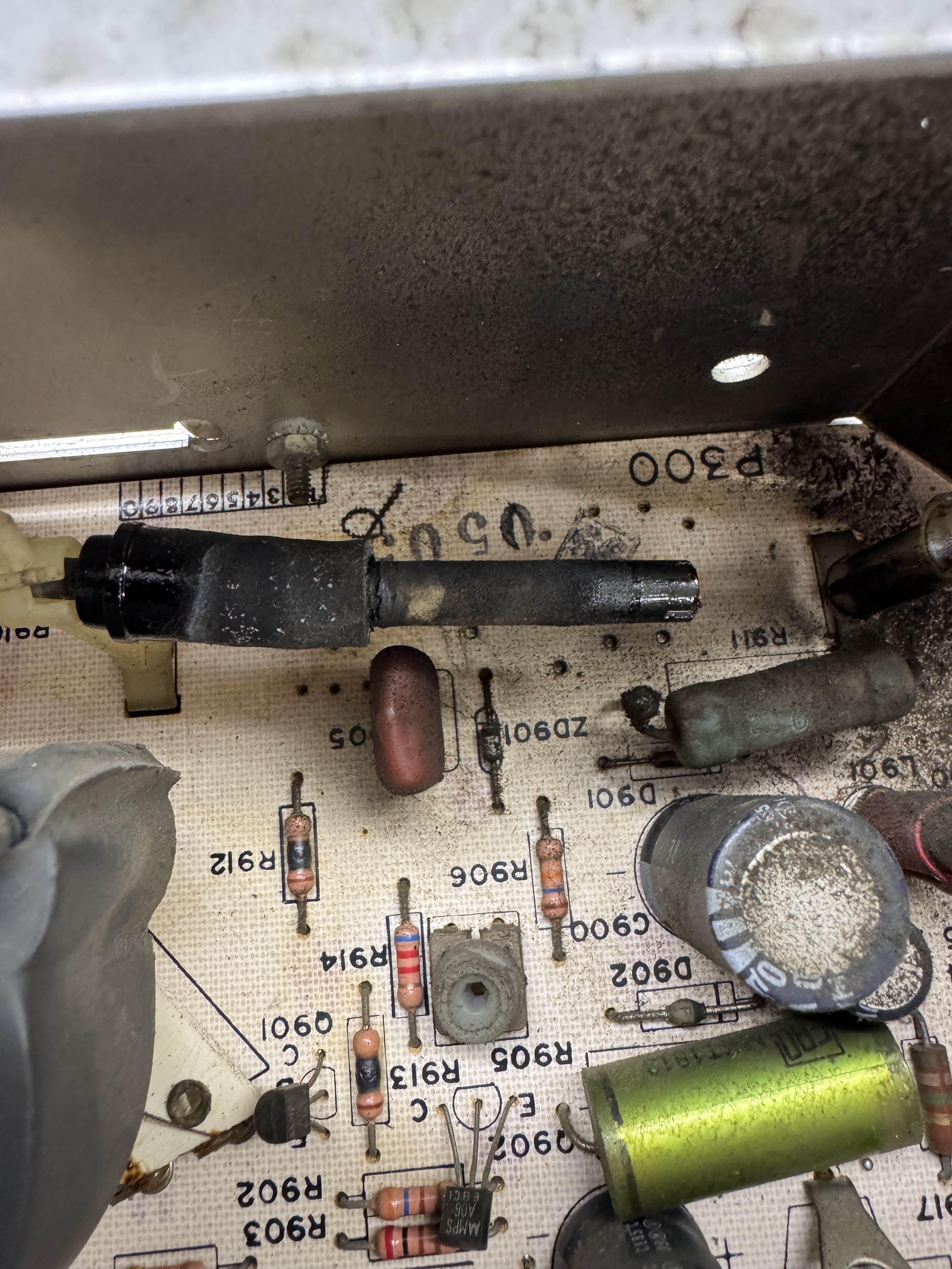
This HV transformer/flyback is not reproduced. When they are dead – they are dead. I test the HV doing as little as possible so that I don’t waste a lot of time finding out the entire chassis can’t be fixed. This one was pretty dirty and most importantly – the HV wire leading to the anode cup had been chewed by mice down to bare wire at spots. Fortunately I had a replacement from a dead HV I was able to salvage.. I had to take the HV cage apart just to work on it so I did my standard checks. As it turns out Q903 failed shorted (replaced it). The brown you see under the chewed HV wire was from the mice (ewwwww). I was able to test and the HV transformer worked.
Once I knew I wasn’t working on a dead chassis – I washed the chassis and got rid of the mice ‘stuff’. The deflection board wasn’t much better. Reassembled and tested the repaired HV unit – it worked.
Once the deflection board was done being refurbed – powered it up and the spot killer was on. If I turned the brightness all the way up I could see the screen with retrace lines. After working through it for a while I determined it was the spotkiller circuit itself causing the issues.
It also had a wrong fuse and I replaced the HV adjustment pot.
Replaced Q500,501,502 and restored full functionality. Tested for 5 hours on this one just to be sure.
Chassis works!

Very Nice Work! You really know what you’re doing on these! I’d like to send you a Deflection Board from my Atari Asteroids Cabernet, it’s from a 15V2000 Monitor. I sent you a message via email. Thank you,
Andrew F. Lowe