

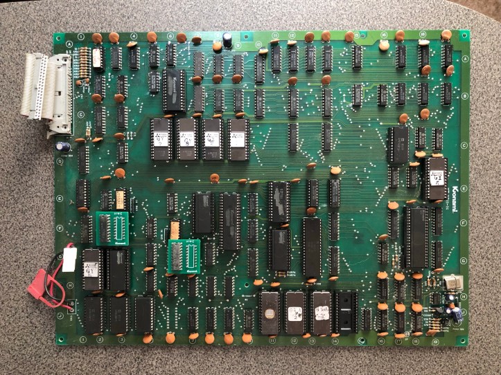
Here’s what it looks like when its done.. But it was a long road to Earth..
My real motto for this post is:
You can’t learn to swim by reading a book – you have to jump in the water.
I started by jumping in the deep end, very deep.
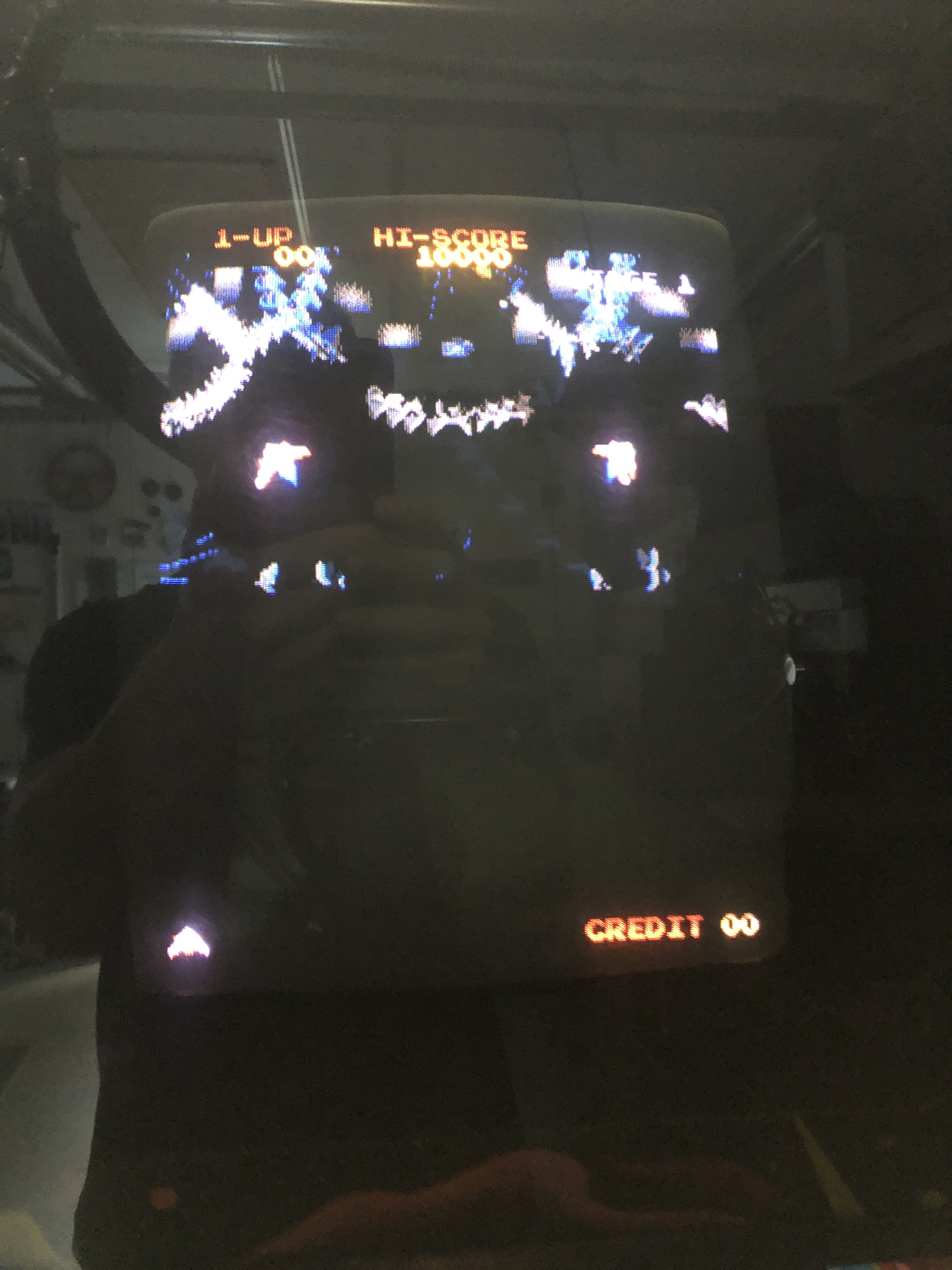
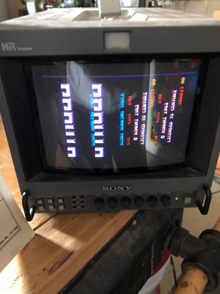
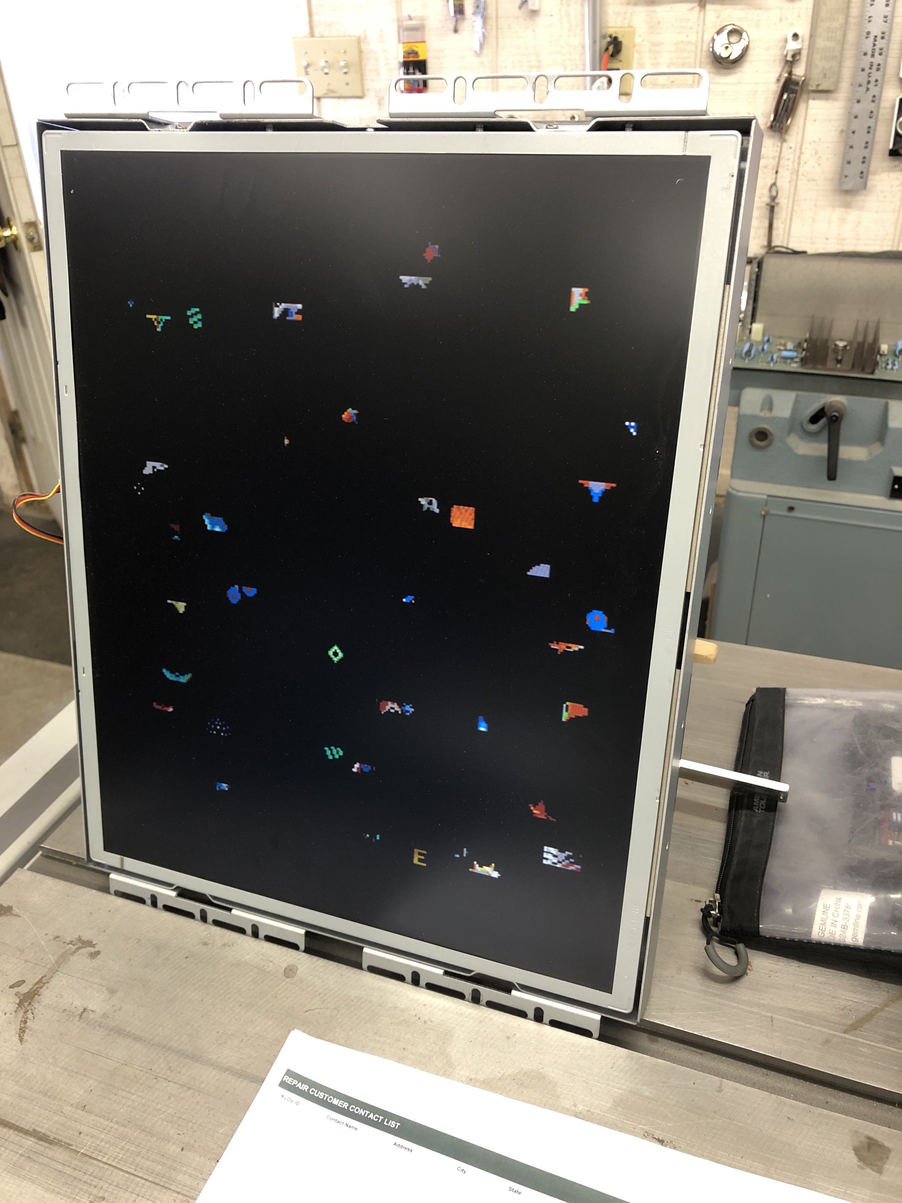
When I picked up my Gyruss machine – it was stone dead. Once I got the power supply fixed – the first screen I got was this:

Not too bad! The character graphics were a bit messed up, no ships/sprites – but you could hear them and see the score change. So off to a good start. My cabinet came with a full set of manuals and schematics and I used them for the initial triage. I quickly decided to bring the schematic to Staples and do a full scan and print of it on large paper so that I could write all over it. The scans on the internet are just a bit darker – but if needed I could rescan mine and have the contrast set.
There are a second set of schematics that were generated and seem to be more readable and have a few corrections here and there. Pg31.
I’m spoiled on Atari Schematics. They are clear, well documented and divided into multiple sections providing significant information on the operation of the circuitry. Gyruss? Not so much.
My normal routine is to pull all socketed chips, clean the legs, test any ROMs against the Mame set and burn replacements. On my first pass through – ROM GY5,6,7 checked bad.. The majority of the ROMs were Hitachi HN482764G’s. A few were Mitsubishi M5L2764K’s (which I didn’t notice – this will come back to help and haunt me later). I ordered some Hitachi’s from eBay and waited.
Once they showed up, I burned, verified, romident’ed the new ROMs as per my habit against Arcade Rom IDentification Tool and continued to try and diagnose the board. Two things were going on with it. First – the character graphics were messed up with the background colors incorrect. Second – no ships.
Not knowing anything this board and almost no help from the schematic – I started documenting what the different parts of the circuit did and what signals did what. In general – the upper right part of the schematic runs the sprite engine and the lower left area is where the character graphics work is done.. I probed counters, gates and everything with the scope looking for stuck or dead lines on the character side and really could not get anywhere. Somewhere along the way I decided to swap the ‘083’ custom chips at 3G & 7F just to see if anything happened – the graphics changed from a flat look above to a pixelated pattern that looked like a RAM issue. But no real progress to speak of.
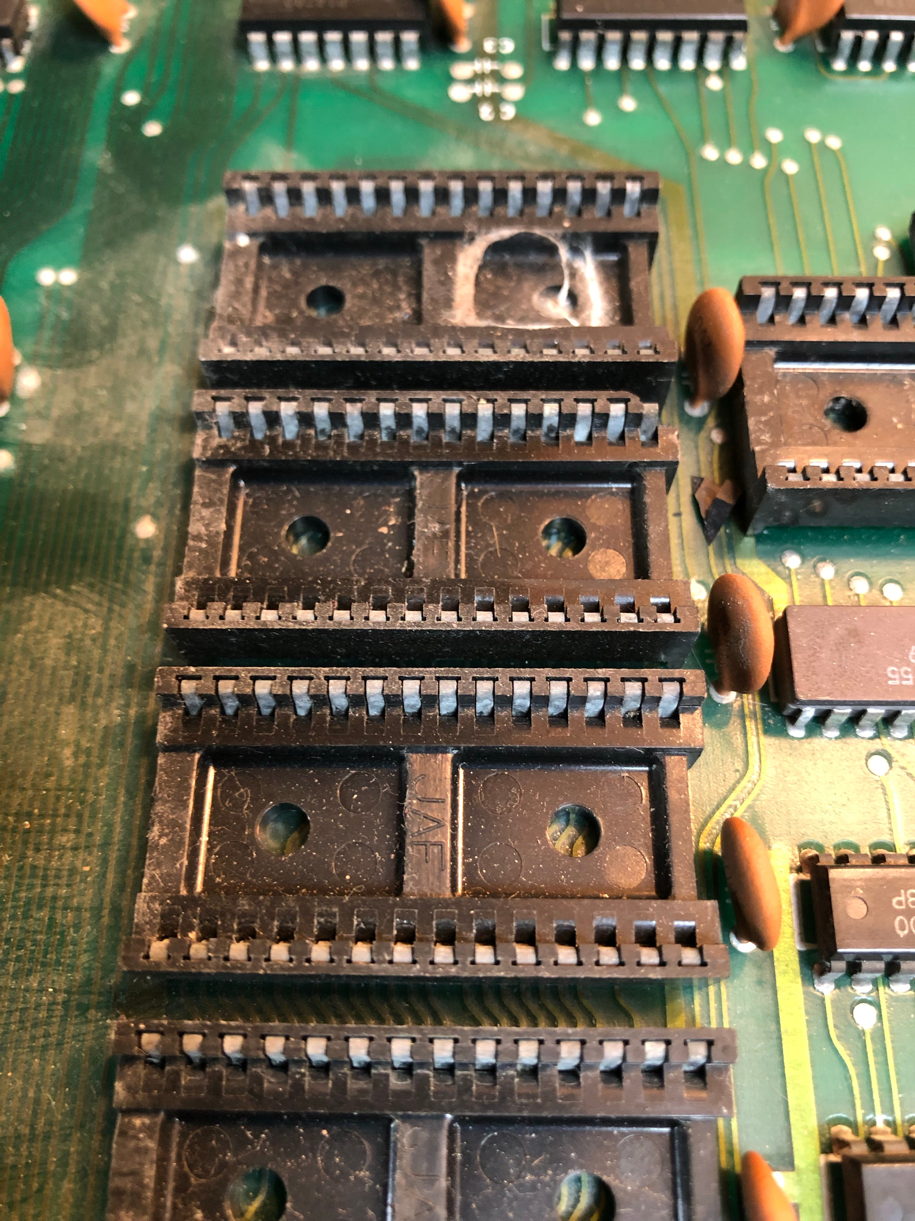
Next I turned my attention to the Komani K1 custom chip – which I’ve come to learn is a modified 6809 processor that does some opcode decryption by swapping opcodes around – or something to that extent. Pretty much everything around it was dead. Now an then I got it to execute and data was flowing in and around it.. But Pin13 is the one that signals RAM R/W – it wasn’t toggling. At some points, part of the circuit would run and at other times it was dead. It felt like chasing ghosts. The sockets are the really crappy single wipes that you can pop of the plastics and desolder each pin very easily. I made the decision to just replace them all. In hindsight, it was overkill (probably)… but this board will never have a socket issue.
The good news – I didn’t make it worse. The bad news – I didn’t make it better. I added sockets for the RAM at 17C and 11A, 12A, 13A, 14A. Swapped in some new RAM.. Still everything was dead. Looking at different parts of the circuits with the scope, there were some LS245’s on the bus that the K1 processor was on that ‘could’ have been part of the issue – and were easy to swap. I ran around the board with the logic comparitor and nothing jumped out. I swapped in a new LS138(19C) and LS139(15A) even though I was certain they were likely ok – just because they were controlling the major lines going into the sprite circuitry. Nothing..
Finally I decided to again focus on the character portion since it was a known broken part of the machine. I kept coming back to the ‘083’ custom at 3G, but swapping and testing in the area didn’t help much. A planned visit to the Chicago area to a friends house allowed me the opportunity to bring my boards and swap custom chips from his Gyruss to mine and see if it helped.
AANNNDDDDD…. Nothing. I didn’t spend a lot of time swapping parts with his board.. We had other things to do..
I do not have years of experience – but I’m an above average problem solver and I was stumped. Luckily – a broken Gyruss board set came up on eBay and I was able to get it. Having something to compare mine with – even broken – was better that nothing.
New board set shows up (I’ll call it board2) – Its almost identical in failure to mine except the character graphics are all good – no screwy background colors. Sprites are dead. Step 1 – pull the ROMs, check against Mame.
GY5,6,7 – show as bad ROMS. (keep in mind – this is a month after starting on my board that came with my cabinet). I burn 3 EPROMS, plug them in.. character graphics all screwed up.. WTF? Then I remember – these same 3 ROM’s checked bad on my original set (board1). That’s too much of a coincidence. Here is where I notice GY5,6,7 are Mitsubish EPROMS and every other EPROM is a Hitachi. I learned A LOT about EPROMS and my programmer over the next day or so..
First I thought it was some sort of speed issue related to the EPROMS, but they seem to have the same response time according to the datasheet (I’m no expert – but they looked to be the same). Looking back – I had read the Mitsubishi M5L2764’s on my programmer (GQ-4×4) as the Hitachi HN482764. I had no idea they would not read the same since they should be pin compatible (Experience +1) and hadn’t noticed they were different chips at that time. That said, I had burned new EPROMS on Hitachi’s, verified, re-read and checked them before putting them on board1. They SHOULD have worked even though the originals were read incorrectly.. But they didn’t. Research showed that these EPROMS like the SLOW WRITE setting on the GQ-4×4 – the default for these are fast write on the GQ-4×4. WFT?
The programmer has a devices.txt file where you can modify, change, delete existing that you can get to from the menu -> Device -> User Folder
However – mine also has a file called customdevices.txt – you can add ‘new devices’ to it without modifying the original devices.txt file. Much easier to keep track of changes. I added these two lines to that file. These will force a slow write. You should be able to add that file if its not there already and have it work. It can be done from the application too – but I can’t forget this way.
Name=”HN482764-SLOW”, ID=”XXXX”,Class=”2764(21V Vpp)”, Category=”EPROM”, MFG=”HITACHI”, Speed=”1″, Message=”Apply external power”;
Name=”M5L2764-SLOW”,ID=”XXXX”,Class=”2764(21V Vpp)”, Category=”EPROM”, MFG=”Mitsubishi”, VCC=”5V”, WVPP=”21V”, WVCC=”6.2V”,BVCC=”5V”,RVPP=”5V”, Speed=”1″, Message=”Apply external power”;
I quickly figured out the Mitshubishi’s needed to be read as M5L2764’s. So I re-read the board2 EPROMS the correct way and verified they were good. Then I popped them into board1 – the Sprite engine started! The sprites themselves were a mess. But the engine was running. The character colors were still messed up. I popped the ‘083’ custom (3G) from board2 onto board1 – character colors fixed! I had suspected that chip was causing problems all along. Having the correct ROM (GY6) with the good custom’083′ got the whole character side running correctly.
I had downloaded and burned Shoestring’s Gyruss Test ROM but I could never get it to run. I burned a new one with my new slow setting and saw the output from the test rom for the first time. It told me my RAM at 11A, 12A, 13A and 14A were bad – but they were brand new! (Need to figure that out..) I popped the original ram into the sockets. Board fixed!
Two days after getting the eBay board I got my original up and running. At some point I must have ‘accidentally’ fixed the sprite engine issue on this board by replacing a LS245 or something that allowed the K1 to boot properly.
Having EPROMS that test good, validate good and do not work in actual use was a surprise. Rewriting them on the SLOW setting fixed it. Yet another experience point.
On to Board2
Now that board1 was 100%, I retested the original EPROMS GY5,6,7 from board2 and they checked good – not sure why the device type matters… but OK. So they were not part of the problem. Character side of the system was good on board2, game plays and scores properly. This was simply a sprite engine issue.. All too familiar.
After taking a breath and thinking about all that had happened on board1, I took a new approach to the sprite engine on board2. I started looking at it as a computer within a computer. It needs to be get a reset signal to boot and run some code in order to start. CPU, RAM ,ROM plus whatever connects them. If it had a watchdog like the primary processor – it would have been barking like crazy.. This computer within the computer doesn’t have the circuitry for a watchdog, but essentially that is what was going on.
Board1 was working 100% now as I mentioned – the first thing I tried was pulling the socketed custom chips (and associated ROMs) associated with the K1 and putting them on board2 . No difference – so I was good there. Shoestrings Diag ROM showed good primary RAM and ROM and a dead Konami Processor, check, knew that..
Using the scope – I looked at the supporting chips for the K1 LS138 @19C and LS138 @15A and a few gates around there.. The appeared to be doing what they were told – which was nothing.
I socketed the RAM at 11A, 12A, 13A, 14A and used the known good ram from board1 and gave that a shot. BTW – I’m just starting to understand the value of the Fluke 9010a. A 6809 pod I think would have found this issue. I’m not 100% sure since it is a 6809 Konami custom. But maybe. I do want to join the Fluke 9010a club at some point.
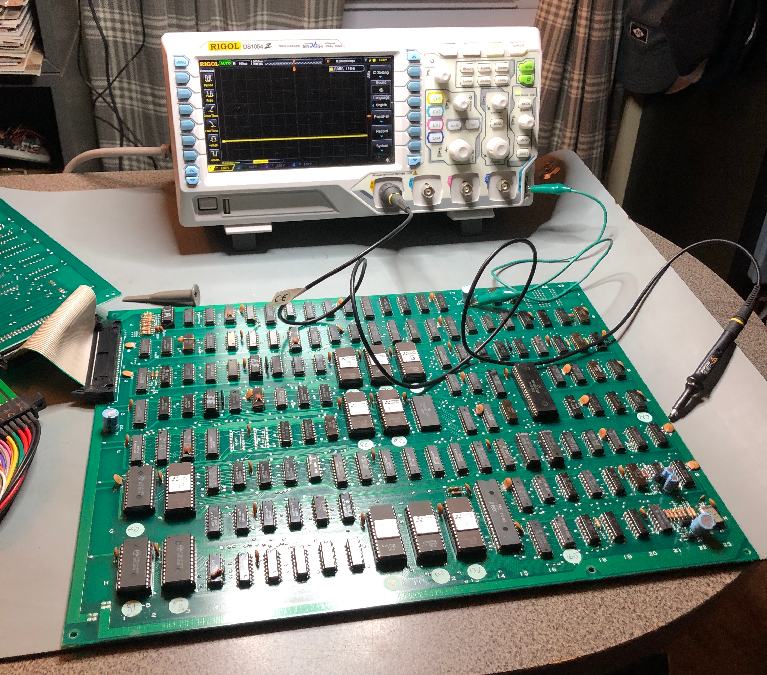
Moving on it had to be either bad addressing or bad data getting into the K1. Probing the data bus, bit0 (9DB0) seemed to have almost no activity except for the occasional blip. The other data lines all had plenty of activity. The first chip on the bus was LS245 @14E. It had good data going in and a flat line coming out on the shared bus. I pulled the chip and just left if off the board for now. The LS245 at 14E checked good on my tester. The bus was still running with data flowing and 9DB0 was still basically inactive vs the other lines.
The next LS245 on the bus was @17F – I pulled it and checked it:

This was very exciting of course! The tester can handle the tri-state chips no problem. This one is truly NG.
I soldered in the two replacement LS245’s and the sprite engine booted!
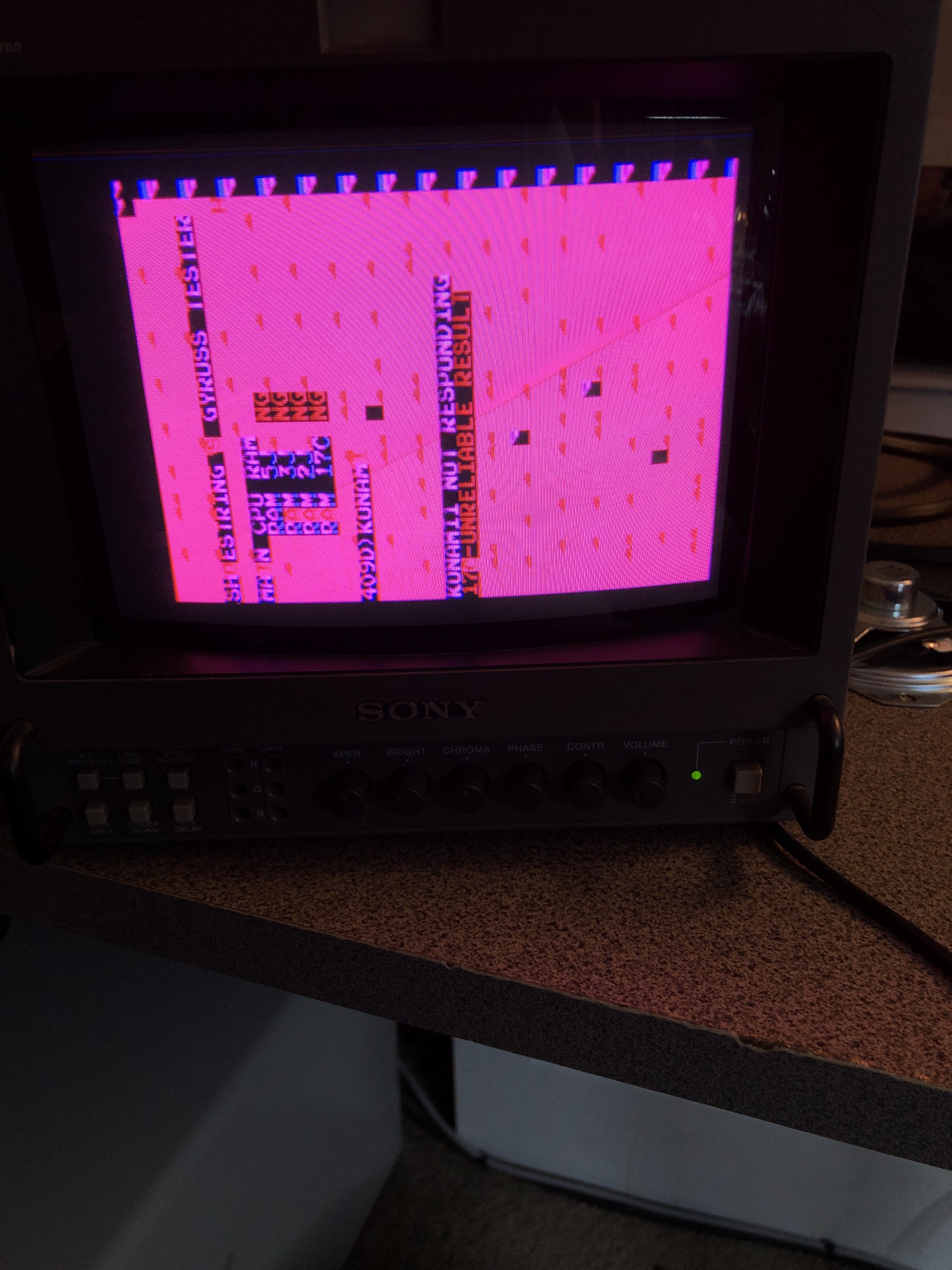
But it was messed up. Still way past where I was before.
At first I thought I had a counter issue since the screen was only on the top half and mirrored. The diag ROM also complained that the RAM at 17C was unreliable and that the K1 wasn’t responding (which it was in reality). It took a little while to find it – but the root cause of this was a lifted a pad (they are tiny on this board) on the component side pin18 (9DB7) @14E. The trace was right up next to the pin, just not touching. Self inflicted wound there.. It was so small..
Board2 Works!
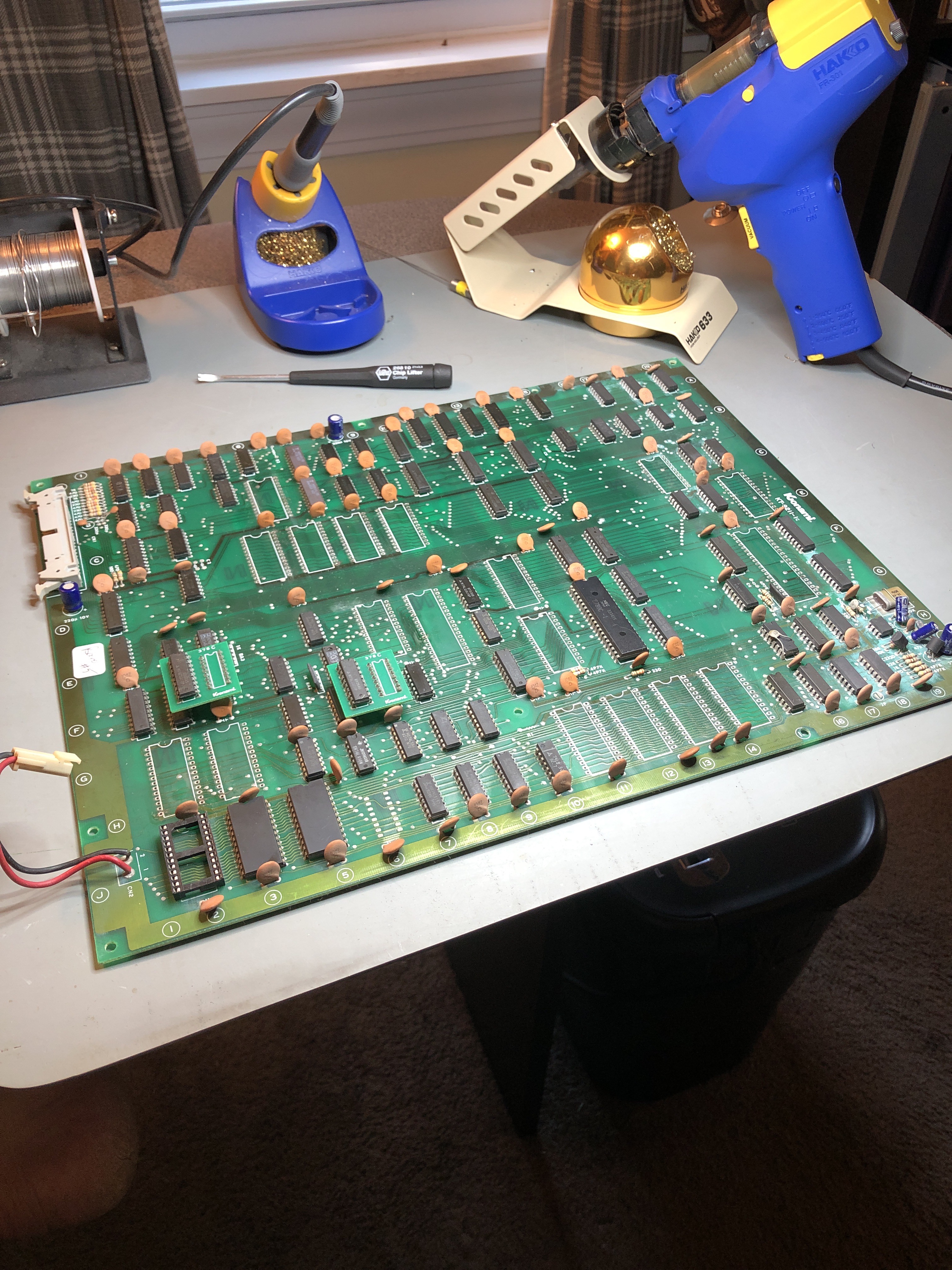
Learned two more things from this – closely reinspect desoldering after cleaning up the pads on both sides (experience +1) and I’m going to upgrade my desoldering gun. I purchased an inexpensive ($140) setup that has worked reasonably well. I didn’t know how much I would love board repairs when I started so I went in a little light on this tool (I should have known better).
I’m getting a new Hakko for Christmas. It will be quieter, more compact and overall a better tool. Having a second boardset for comparison purposes was huge. Having EPROMS that validate good, but do not run on the board was an eye opener – this cost me some time – but now I know what I don’t know.

Board 3
(this repair still under construction – check back for more)
I’ve been watching eBay for more Gryuss boards to repair and one popped in for a good price. Normally I look for NON-BOOTLEG (i.e. original) boards. Looked right at the description and bought a bootleg by accident. Oops.
The issue is no schematic diagram to work from. But – a new challenge!

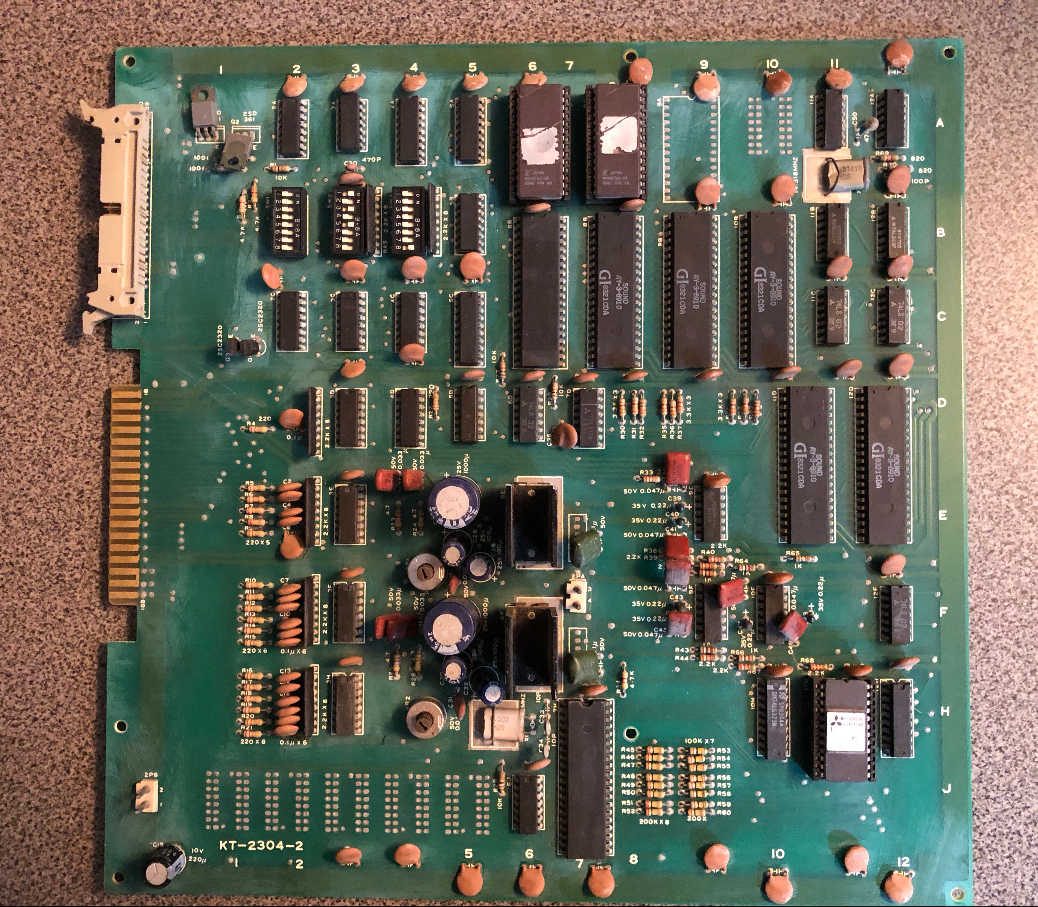
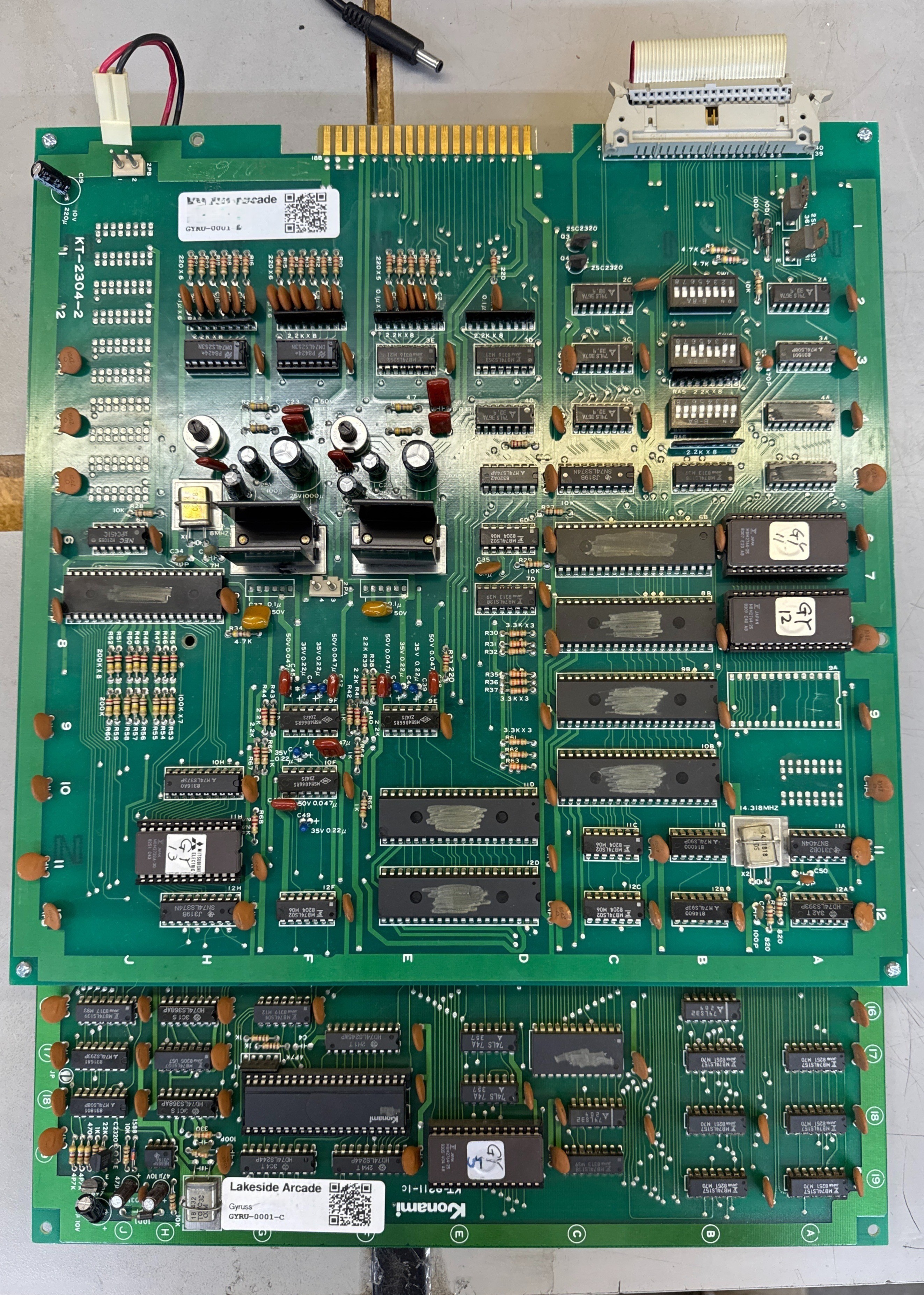
Bootleg on the left and original Konami board on the right. One nice part about the bootleg is that there are no custom chips. I pulled, dumped and verified all the ROMs and they were all perfect. Another issue is that it did not have an open diag socket (14J) to plug in Shoestrings diagnostic ROM. He has a second version of the ROM that plugs into the #1 ROM position. It was specifically made to help diagnose boards with bad RAM at 5J.
I wasn’t sure it would work correctly with a bootleg, but was confident it should since the game ROMs were identical – which meant all of the addressing and RAM locations had to be the same. The bootleg board isn’t an emulation – just a different way to build the same thing.
On first power up the board would show the grid screen and just go into continuous reset. I plugged the diag ROM and it started, but the screen output was a mess. Through all of the garbled characters it looked like it was telling me bad RAM – which makes sense because the game would not start and the ROMs were good.


The first 3 RAM chips Gyruss uses are 5J, 3J, 2J. 5J also seems to be the RAM workspace for the game code. I pulled all 3 RAMs and tested them on my RAM tester (Inquisitor). The RAM at 5J tested bad, the other two tested good. Sockets installed and I had a new RAM chip I put in for 5J.
The new RAM helped move things along. Sometimes the game would boot, sometimes it would reset. The sprite engine ran perfectly once the game started. The character graphics were a mess. I started reverse engineering parts of the circuit and putting little dot labels on the board showing where chips would be in the original schematic. The jittery character graphics are above.

I did manage to reverse engineer one of the custom chips on paper – I beeped out the lines from the GY6-ROM that normally goes through the ‘083’ custom and into the PROM at 3E . The bootleg did part of that custom work through 3 standard TTL chips (2 x LS194’s and a LS157). That part seemed to be working watching signals in/out via the scope.
Scope came in handy along with the DMM for locating connections and determining what pins were active.
I decided to go back to the RAM again – put the 2 working original RAMs in place at 5J and 3J and the new RAM at 2J. Board booted and ran almost completely glitch free on the graphics side. Since I socketed all three rams – I’ve been Tetris’ing them around to see how they respond, etc. If I keep an original in 5J the game boots.
Ran it on the bench all night and the board didn’t reset (I had 1 credit when I went to bed and when I woke up). Final verdict is it had a bad ram at 5J (on the schematic). I had some RAM (6116) I got from Arcadeshop (I believe) which is either too slow (or maybe too fast?). So the graphics are glitchy.. Game will not run with the new ram at 5J.

Ordered new MB8128-15 RAM which is the same as the Konami boards – graphics glitch free. When testing the board in my Gyruss cabinet – two additional items came up.
First – the board was jumpered to run from a single speaker – not stereo. The original board had a nice jumper block for that. The bootleg has a wire soldered in. I removed it.
Second, only faint audio from the right speaker. All the sounds were there – just very low. Left speaker was normal. The original board had LA4460 audio amps with heat sinks and the bootleg had LA4461’s without heatsinks. There was no easy way to test them except to swap them with each other. I was 98% sure the right channel amp at 6E was the issue. Pulling the ‘good’ one from 6F and moving it to 6E confirmed it. All of the remaining right channel circuits are good.
Once the bad one was out – I did notice this.
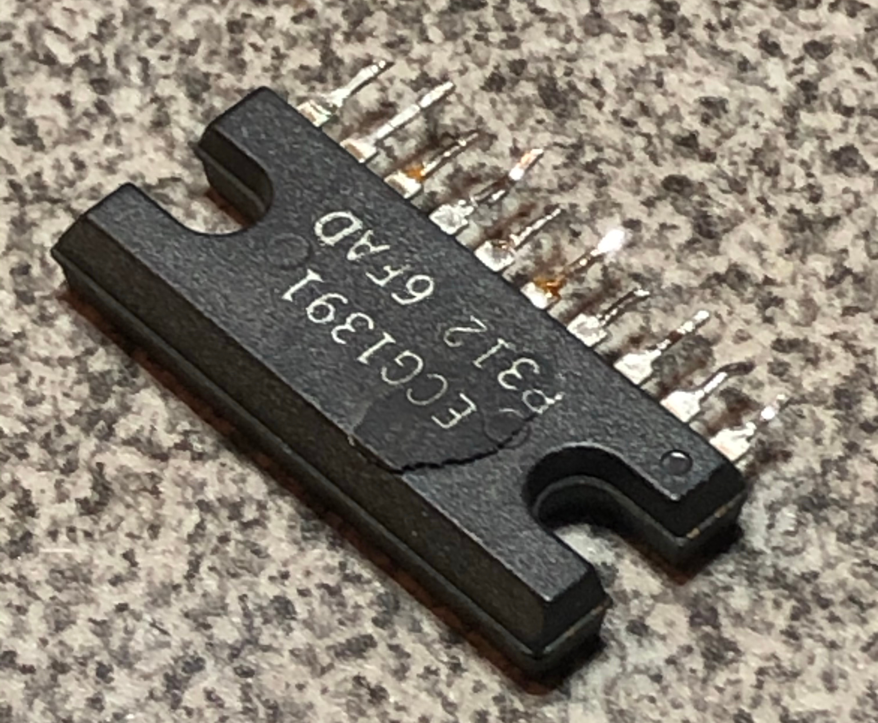
There was a faint hairline crack.. I gave it a little nudge to show this. Heat. I could not find the exact style of heat sinks used on the originals, but I’m getting some small stick-on ones to give these a fighting chance. Received the new audio amp chip, soldered it in and added a couple small heat sinks. Sound issue fixed.
Ran the board and noticed glitchy sprite graphics, relatively minor. Looked like it should be RAM. Pulled and tested the 7A, 7B RAMs. No issues. The test ROM doesn’t check these as I understand it. Even though the ROM does test 14A, 13A, 12A, 11A – I pulled and tested those too – no joy. Shoestring’s diag ROM has a character and sprite test section. The sprites are glitchy in the static test ROM too.. Certain ones tend to ‘bleed’ a bit. Because they were socketed, I checked the PROMs at 2A, 3E, 6F – 6F being the only one that could have had an effect.
I rechecked voltages across the board and they were in the 4.91v range. I bumped it up to 5.01v just to make sure there wasn’t an border line issue – there isn’t.
(more to do here)
Board 4
I pulled another board out. The stack was a little dirty but the only visible issue was a burned edge connector that had a solder blob on it.

The main PCB has these Konami risers for a couple of chips. The look factory and are soldered directly to the board.
After pulling all the socketed chips, testing, etc. There were zero issues. Repaired the edge connector and powered it up. Got this. Looking at the schematic and playing the game – there were glitchy sprites with lines running through them and the character graphics would sometimes double up depending on the game code execution.
Looking at the schematic – I pulled the EPROMs one at a time and determined 7C was the ROM that controlled the sprites that were glitchy. Telling me I was in the right area. I was hoping it was not a custom chip – but swapped the 083 custom at 7F with a known good one from my board. The ‘bad’ and ‘good’ ones both ran fine. I swapped them back and all is good. For good measure – I bent the legs out a little on the chip for a better connection in the socket. These particular sockets are actually pretty good so I won’t be replacing any. There may have been just a little something causing a weak connection.
I had a second glitch at one point and replaced the socket – zero issues since.
The board had a couple of 220uf caps that had been damaged and the power connector between the boards needed the wires to be trimmed and resoldered.
Final resolution:
- Repaired burned up edge connector
- Replaced broken caps
- Cleaned and tested board
- Replaced socket at 7F
- Power lead between boards had frayed solder connection.
- Trimmed and resoldered
Board 5
Pulled my last Gyruss set from the pile.

These are an older looking set. All of the sockets are oxidized and the boards need a good cleaning. This set has never been worked on. My guess is it stopped working many years ago and got stored.

I went through my normal checklist and removed all the socketed chips, cleaned the legs, tested ROMS, etc. I popped and replaced this socket – they are not going to be reliable. Once done I’ll resocket the entire board set. There were 5 EPROMS that read bad during testing. I clean the legs using a fiberglass pen. It gets the flat sides of the pins pretty shiny, but in this cases I had to rub them side to side in the EPROM tester ZIF socket to clean the edges enough to get proper contact.. In the end only 1 EPROM read bad.

After the full clean cycle and testing for shorts, connected it up and got this. I was rather surprised. Game runs!
Issues at first boot:
- Sprites showing up as blocks
- Colors messed up
- No sound
- Diag ROM showed bad RAM @2J
- Diag ROM shows bad RAM @17C – but intermittently. It does always run however.

Confirmed – RAM @2J – bad. RAM @17C is soldered to the board. I will likely socket/replace it. My guess is it’s marginal.

Replacing the RAM @2J fixed the colors. Sprites still messed up. Reseating ROMS in these bad sockets fixed the blocky sprites (as expected) the main board is working – just needs maintenance.
On to the sound board
Plugging in a known working sound board – all the sounds are fine. My issue is confined to the sound board.
First thing I checked was to see if the CPU was running – the crystal @11A seemed to work when it felt like it. I was able to jiggle it a bit to get clock on the CPU. However – still no sound. Probing around I kept coming back to poor signals on the data bus. D5 was was only peaking at ~3v. Diode checking the CPU, RAM and all the other chips on the bus didn’t reveal any obvious issues. I was pretty sure the CPU was not booting.. All of the other Gyruss sets had working sound boards. This is my first time through one.
Based on the condition of the sockets – I replaced all three on the sound board to eliminate them as the problem.
The circuitry is a bit simpler than most main boards – no watchdog – so no easy way to know if its booting correctly. I was thinking the issue has a tri-state chip somewhere – however almost everything shares the bus. I ended up pulling the CPU, socketing it an testing – it was fine. Pulled the first RAM @5A- no issues.
Activity on the LS138 @7D was strange – plenty of signals in – only one select pulse out. I piggybacked it and did some comparisons and they seemed ok – but swapped it anyway in the event it was marginal. No change.
At this point I decided even with all of the address line and data line activity – the board wasn’t booting. Not sure why – I pulled the first ROM GY11 and popped in another from my good board and the sound board came to life.. ughh.. Bit again by a ROM that verifies and tests good on the reader – but will not run in circuit.
When I burned new ones on fast (and they really needed slow) having them not work made sense in hindsight (see Gyruss board#1 repair for this story).
Seems strange that a factory ROM failed this way. Experience points +1 – even if a ROM tests good – don’t always trust it. Pop in a known good one just to be sure.

Sockets removed – that’s a lot of pins.. This will be very reliable.
No issues after full burn-in cycle.
Final resolution:
- Replaced broken capacitor @A13
- Replaced ROM GY5, GY11
- Replaced flakey crystal @11A on sound board
- Replaced bad RAM @2J, @17C
- Replaced all sockets on both boards.
Board 6
Received another Gyruss board that booted to garbage.
A quick probe around showed the CPU was running, had good clock. Just the CPU wasn’t booting. I had not dug out the schematics yet and decided I’d piggyback the LS244’s @14G, 14F. The are the first stops of the CPU. @14G – no change.. @14F.. Board booted. Have to like that!

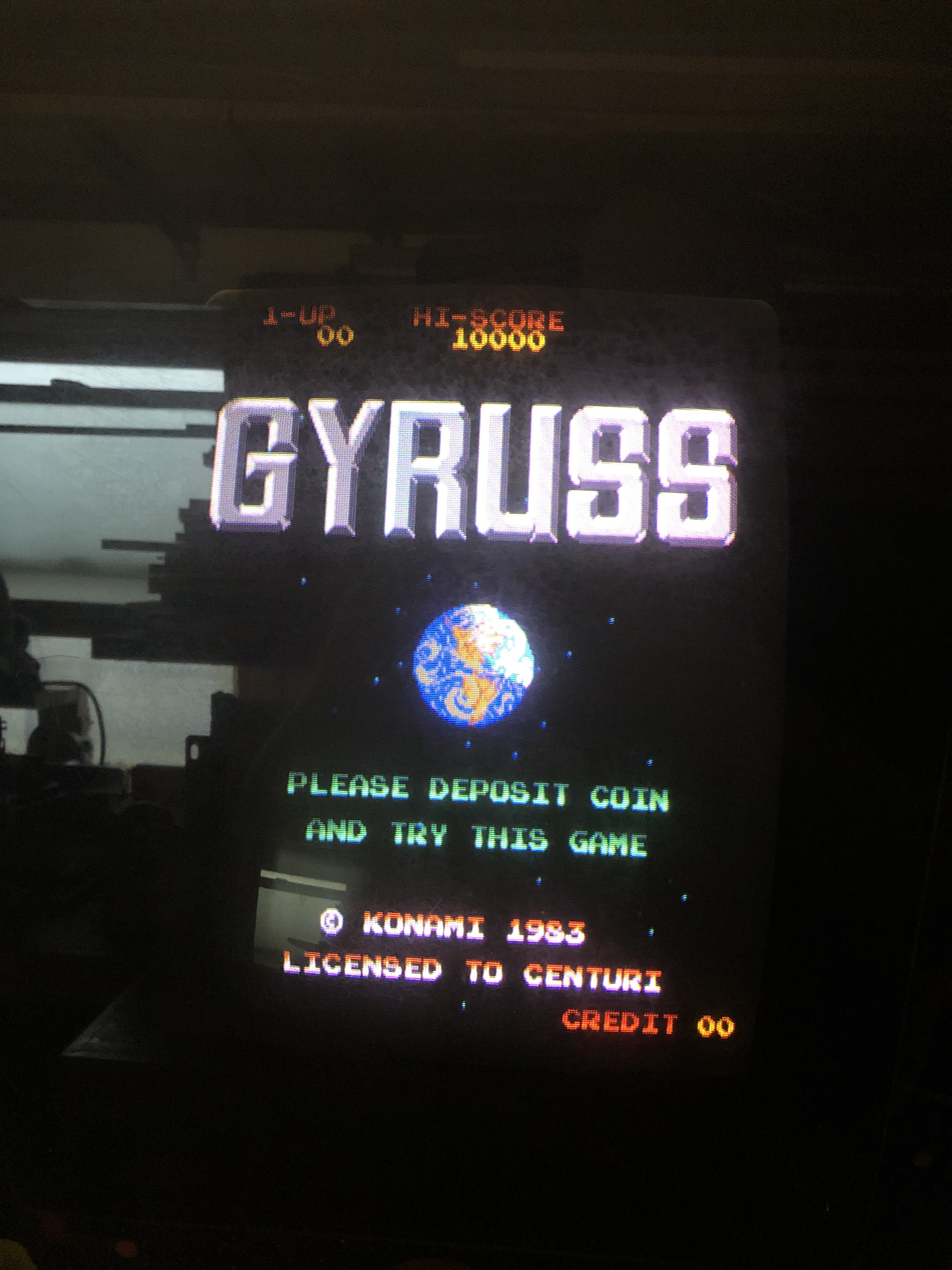
One of my favorite sights..
Once replaced – no sound out of the right side speaker. I immediately went for the LA4460 sound AMP @6E and replaced it with a LA4461 – because that is what I had.. No difference. After messing with it a while and not understanding the readings.. The LA4461 is identical to the LA4460 – except the pinout is reversed.. Read the data sheet!
Put a new one in and the board works!
Board #7 – in for repair
Got this one in for a reported graphics issue. I’d cleaned the chips and discovered a broken leg on the custom CPU.

Difficult to see in this image – but I repaired it. Once I hooked it all up it was running fine. I had not seen the ‘before’ so I got a video from the owner.
Cleaning chip legs and repairing this one corrected the graphics problem.
Board works!
Board #8 – in for repair
Haven’t worked on a Gyruss in a long time. I have to more after this one as it turns out..
Very nice Gyruss.

Reported with no sound – amp burned up. Spent some time checking, but there was nothing wrong around the burned up areas. The caps had been replaced at some point – but I upgraded them in the sound section. Had the amplifier in stock! Didn’t do full board maintenance this time.. Just fixed the sound issue.
Board works!

Great work Bob! I went to turn my Gyruss off last night and found it stuck on the grid boot screen. From reading your article it sounds like I may have some bad RAM. Could you please help me fix this? Thanks, Rob