
*** Newest Entries always added to the bottom ***
I own a Joust upright and cocktail. Fortunately for me their PCBs were in perfect working order. I did acquire a stack of boards to work through and a friend sent me his Joust set. I’d built the beginnings of a bench harness to test a while back. All that said – I got a Defender in for repair from a buddy.
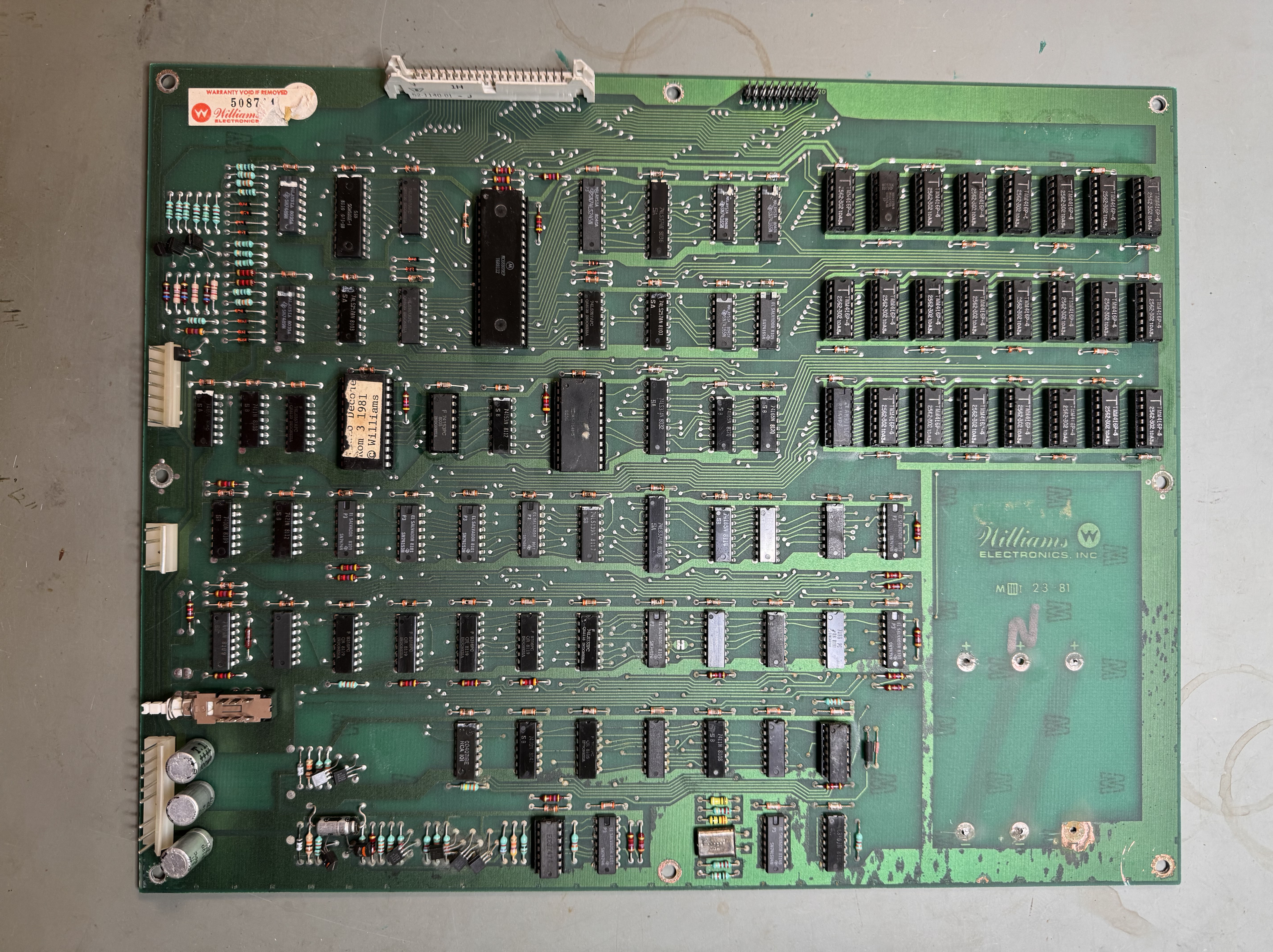
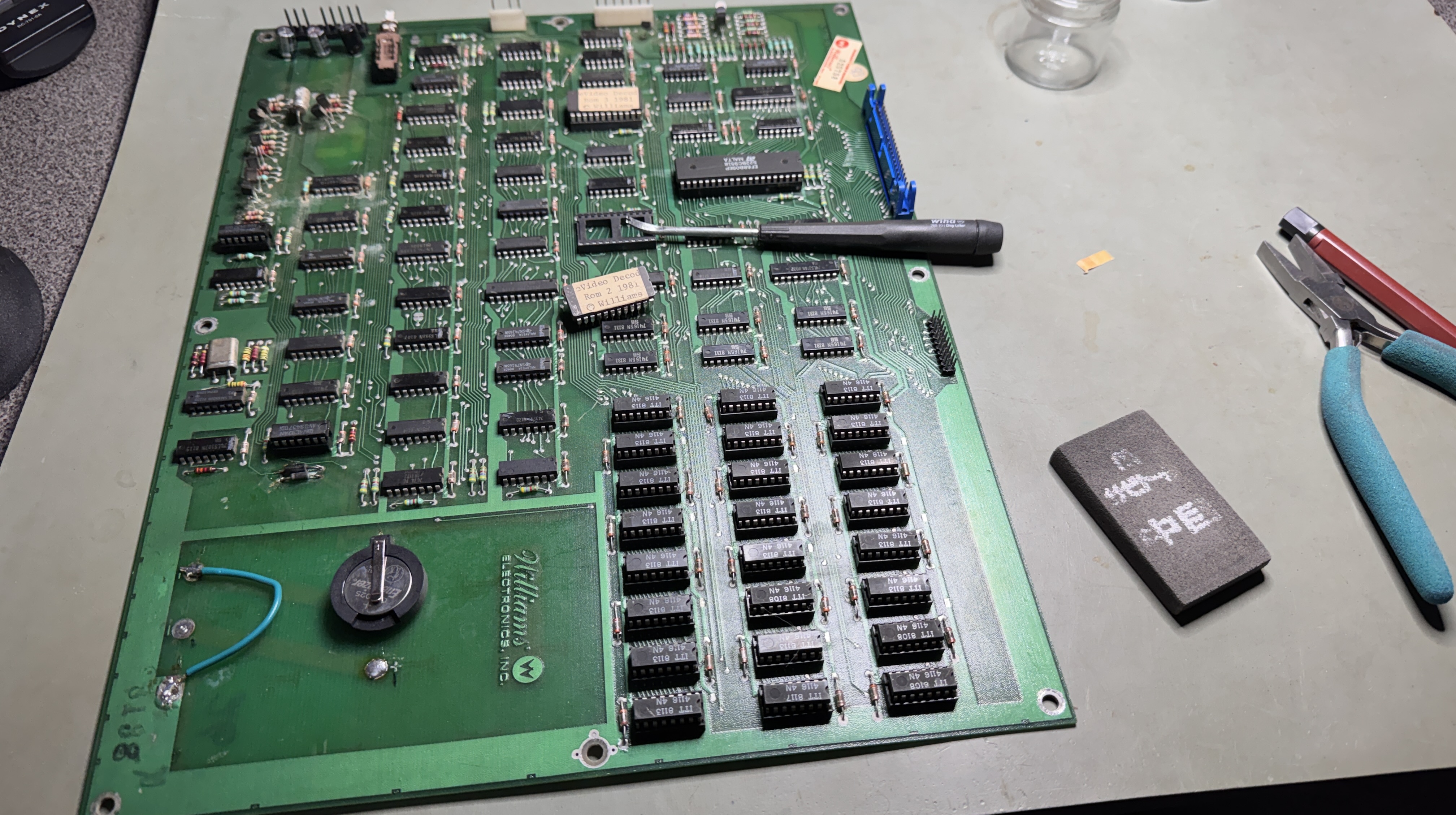
Williams Board #1 – Defender

This one came in basically from a box of parts. I’ve seen a lot of Williams boards that look just like this one. Williams #2 (next repair) is the set from my Defender cabinet and looks pretty much the same.

Krud Kutter, brushes and lots of warm water. This one was particularly brown.
Much better and they are easier to work on when they are clean. The battery holder was broken and damaged. Thankfully the alkaline didn’t spread too much. I’ll likely add a button cell battery backup later.
Once I got it on the bench – it had no 12MHz clock. First thing I did was replace the crystal because there was nothing coming from it. Not the issue. I probed around and the 74LS04@7P seemed to not be suppling an output. I popped in a replacement and no change.. Then I chased ghosts until I realized I put in a 74S04 vs. a 74LS04 (which obviously matters) We now have 12MHz clock!
From here I connected the Catbox to test the RAM and ROM. It took a while to get this going, the documentation was a little thin and it was my first time through it. Things started working once I connected Pin 1,2,7 together on the 7408@4J. This grounds the CPU BS and BA pins. I’d cut the watchdog trace next to @5M while figuring it all out. This turns out to not be necessary. The CATBOX clears the watchdog, I had been reading very early notes on this.
Once this was figured out – I was able to verify all the ROM. Great! Because of how the RAM is designed – the test is slow interestingly enough. The random test failed completely, but the “FF then 00” test would show the first 3 bits on all 3 memory banks as good, then the remaining bits as bad. It took a few tries to tease all of this out. Different tests were returning different results. Since I’m still learning this board set I spent some time working through all the different tests and permutations.
Ran through signature analysis on the decoder ROM@3K – worked great! Then I stepped through SA on the RAM banks. Use the “Force R/W to LOW (write)” and test all the pin2s in the bank. It will show you the known SIG as A0, A1, A2… Then deselect the “Force R/W..” button and check pin14 on the output side of all the RAM. After all this I found that ram 1U, 2U, 3U were not verifying correctly on the output side – these are all bit3 in each bank. Checking the 74165@40 – seemed to be working correctly. Checked the 74153@36 (which had been previously socketed and replaced) it was bad and corrupting MA3. Replacing it got the all RAM banks responding on all the bits now. From here there were about 5 bad RAM, showing as missing bits. I moved them around to different locations to verify they had failed. Replaced them and all RAM now check good. Note the CMOS RAM checks as only the upper 4 bits working. This seems to be inconsistent. Occasionally it shows all 8 bits good. As long as the upper 4 are good – I’m calling the CMOS good.

Board works!
Williams Board #2 – Defender
I picked up my Defender cabinet mostly because it was cheap. It is complete and non-working. It’s been sitting waiting patiently as others get restored before it. The cabinet will wait longer, but I’m taking the opportunity to get the boards working while it’s fresh in my mind.


Not too much different from the first, more moldy than dirty. Rotten battery holder and oxidation
First tests, ROM all checked good. There were a lot of bad RAM. I Tetris’ed them around with replacements until I got consistent RAM test results. Next I ran signature analysis on the Decoder ROM and it checked out, but it doesn’t check every single pin.. A few of the pins were floating..
Popped the socket off and Pin 15,16, 17 were broken on the Decoder ROM. I replaced it, the other Decoder ROM and the CPU sockets since they all looked pretty bad.
From here I tried to boot the board, but the CPU was stuck in reset.

Here is the reset circuit – A bunch of transistors which delay the start of the CPU starting up while voltages stabilize at boot time.. There is a good writeup in the Defender Theory of Operations Guide.

This part of the board was a mess and all the transistors were pretty beat up. R60 was the root cause of the board being stuck in reset. I replaced all the transistors because they were pretty frail. Reset issue resolved.
That brought this interesting picture:

Partial screen – colors messed up too – but I focused on getting the full screen back first.
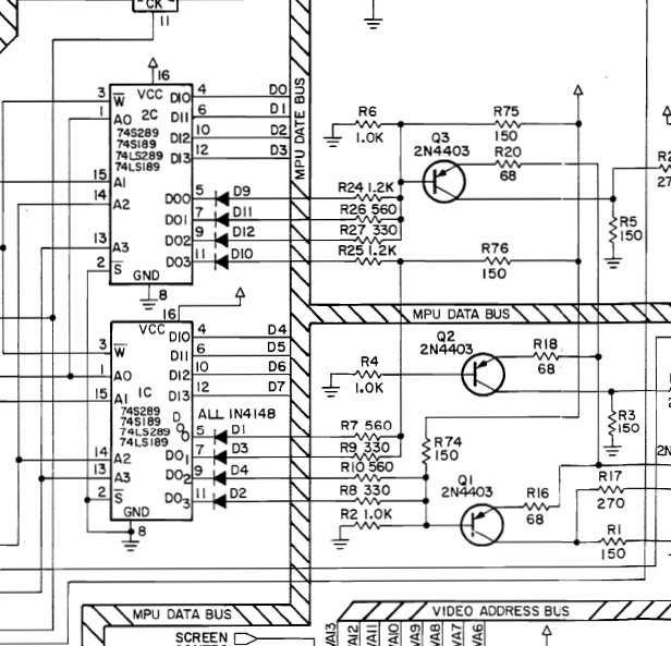

At first I thought it was 74S289@1C (on my PCB it is a 7489) Pin5 had a bad looking signal coming out.. However I found this blanking circuit and that made much more sense. The 7420@5C was causing the partial screen. I now have a full screen, but with missing colors.
While hunting for the missing color issue, the board started to watchdog. I went back and rechecked ROM and RAM and they checked good. I decided to pull the reset pin on the CPU high with a jumper to 5v+ and the board booted fine. Something wrong in the watchdog circuit was my thought at this point.

I followed the reset signal from the CPU back to the 7402@5M Pin13 and it was toggling OUT and IN from Pin6 on the 74393@50. The watchdog was being cleared 74393@pin2. The reset pulse should not have been coming out Pin 6. Replaced 74393@50 – Watchdog issue resolved.
Final issue was bad colors.


This is the color RAM test that is build into the game self diagnostics. It should be the like the color bars on the left. There is another test that rotate through 3 shades of red, 3 shades of green and 3 shades of blue. Each screen should be a full solid color. It shows up as color bars too. The colors were semi-random in nature.
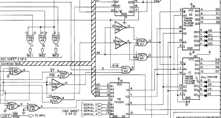
I checked though this area of the circuit and I could mess with the color bars (a little) by grounding out the SERIAL 0,1,2,3 pins@2E. But it was not the root cause. Finally I checked on the E5 signal and it was floating. Followed it backwards since it was selecting the data to use. Replacing the 7427@6K (pin 6 floating) cleared the color RAM issue.

Board works!
Williams Board #3 – Joust
This one is from the box of parts. It started pretty cruddy – but actually cleaned up nice. The battery holder has zero damage so it stays!


I usually clean chip legs at my desk with coffee in the AM.
Once I got it back to the bench and hooked up to the Catbox, no clock.
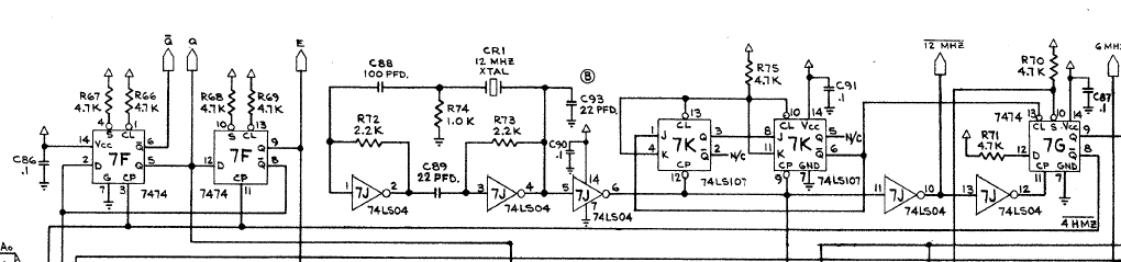
Following the clock with the scope, I was getting 12MHz from 7J and 4MHz from 7G, however no clock from 7474@7F Pin8. Replacing got us clock.
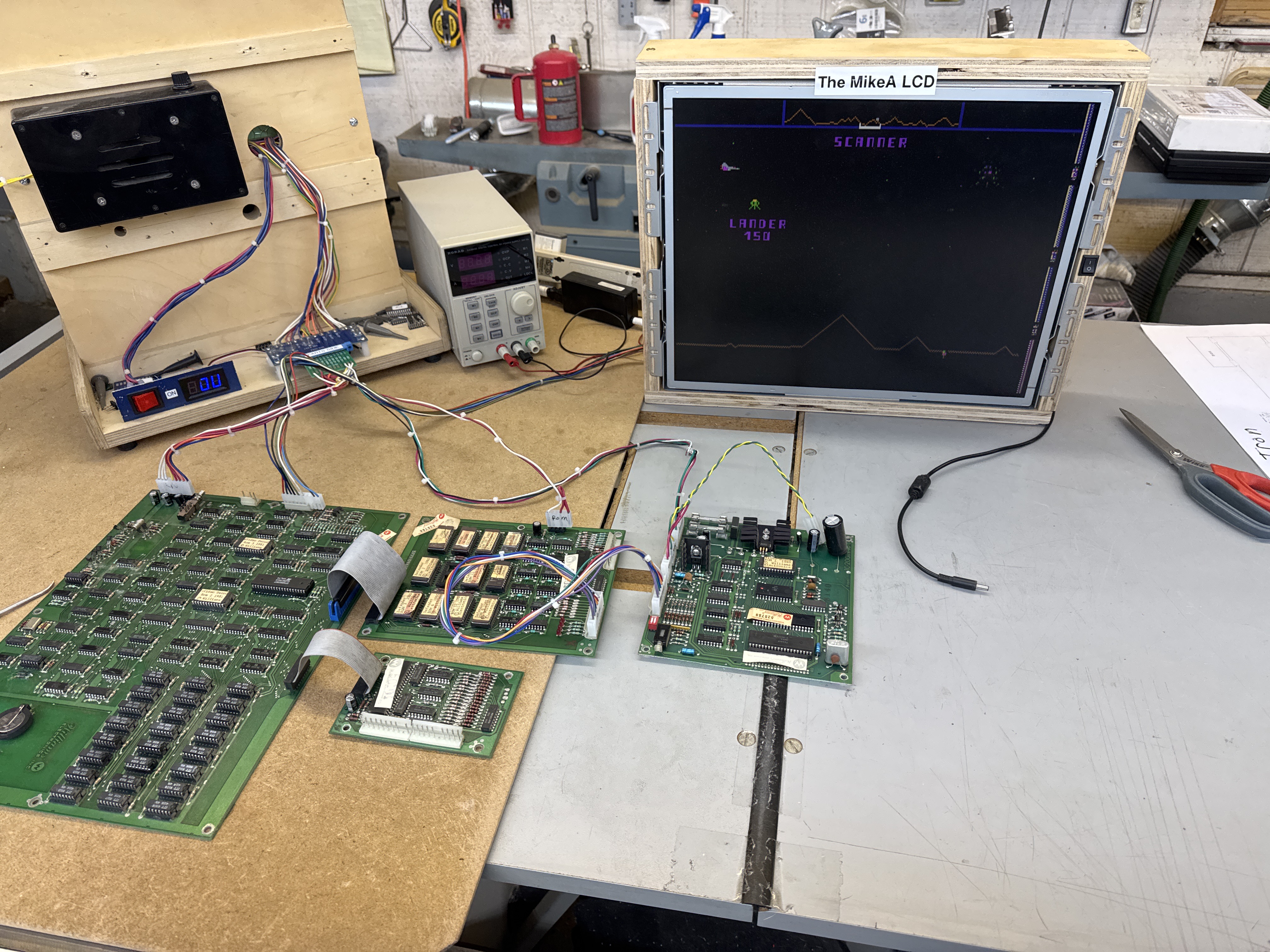
At this point I started to check RAM and ROM. None of the RAM checked out and none of the ROM would verify. I’d already checked the ROM board in my Joust cab and there was nothing wrong with it. This all worked great on the Defender boards so I didn’t suspect the Catbox config at first. After poking around on it a bit I realized it was a somewhat incomplete tester profile. I pulled my good Joust board and worked on updating the FPGA Catbox. The config had just the Fluke checksum so I regenerated all of the other checksums. The RAM test didn’t make sense to me so I borrowed the RAM config from the Robotron config. It didn’t seem to be checking the CMOS RAM either. Basically I reworked the Joust config file.
Testing against my good board set – I could only get ROM11,12 to verify consistently – if I watched closely – the other ROMs would ‘blip’ good occasionally. There must be a timing issue on the test maybe? I had similar issues with the RAM testing unless I used the ‘FF then 00’ test. I could get all the bits to verify using that test.
Back to the board under repair: I knew my ROM board was good – none of the RAM tested good. After checking the board a bit – I discovered the voltages to the RAM were not correct, -5v was -7v and there was no +12v.


The inductor at the board edge had broken free and as it turns out the capacitor at the edge was bad.

Fixing the inductor and replacing the cap restored the voltages. From here it was the memory Tetris game. The CATBOX using “FF then 00” and plugging RAM in got all three banks working correctly.

Board works!
Williams Board #4 – Defender
Had a board from a friend that has been sitting in the shop for a long time. He is getting to the point where it actually needed to be fixed. So I pulled it out and got it on the bench.
Lucky it was nearly working and made things simple. Did a memory test and had a single bad RAM.
No sound at all from the sound board. I swapped the ROM with a different one and got sound! That was easy.. I had not really done any testing. Stepping through the game diagnostics, it had an interesting failure where it repeated a sound, every other sound. This told me it was missing data bit 0 someplace..

Probing with the scope, all of the inputs were correct on both sides of IC9. These are all processed by IC3 and then sounds are generated. Removed the 6820 PIA, replaced. Sounds restored.
Board works!
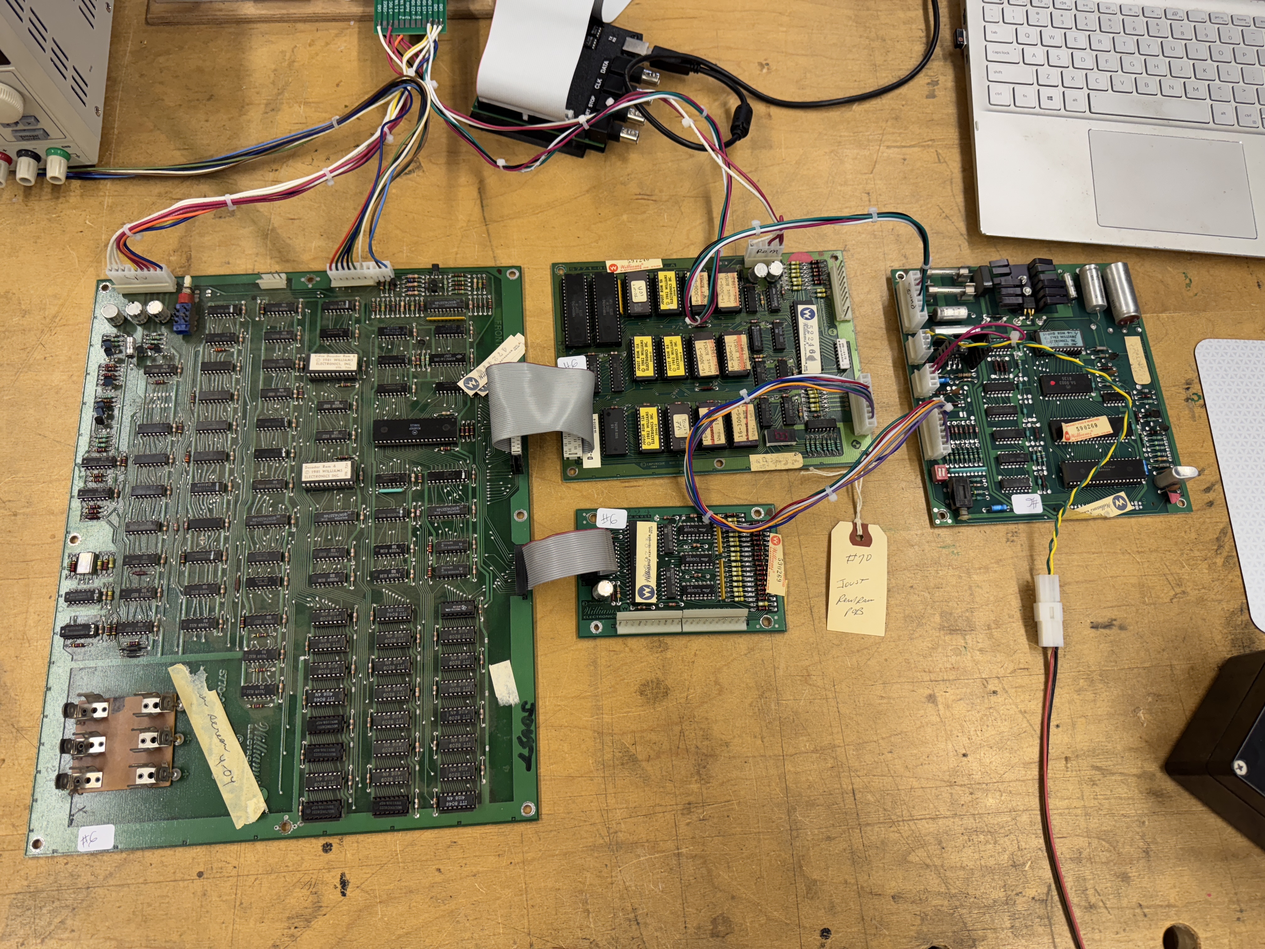
Williams Board #5 – Joust
Received two sets of Joust boards from one of my regular customers

Both included all of the game and power supply boards. Lot’s of chips to remove, clean legs and loog for issues. Takes a couple of hours to work through all of that on this many boards. Once all of that was completed.


I started with the power supply board. The IDC connector got replaced and all of the cold solder joints on the regulator board were cleaned and reflowed. It was not putting out 5V either..

IC2 – LM723 voltage regulator was bad – replaced it and we have 5V!
Once it was all back together I determined that the board was using the 4164 (5v only RAM) vs the 4116 which uses -5v and +12v. The board had obviously come from a cabinet that had a power supply adapter. I modified this board so that no power mistakes could be made.
From here it had 4 bad RAM. Those got replaced and the board ran great. But no sounds.
Determined the sound ROM was bad and the self test sound started working, but no game sounds.
Board set works!
Williams Board #6 – Joust
This set came over nearly identical to the prior one. Same power board issues – re-pinned the transistor block. It also had RAM issues. Replaced 5 bad RAM. Did all of the board maintenance, etc.
Owner wanted remote battery vs. a button cell or NVRAM.

Removed the original PCB battery holder and added a 3 battery remote pack.. I always find them a pain when they are hard wired. So I added a Molex connector to make the pack easy to remove for battery changes.
This sound board was also dead, but for different reasons. Took a little to trace because the on-board diagnostic sound worked. Just the game sounds didn’t. In the end, replacing the 6808 CPU fixed the sounds.
Board set works!
Williams Board #7 – Defender
Board was sent in with reported memory failure and ROM issues.

For me it booted into this – generally a RAM issue. Once I diagnosed it, there was prior work. A machine pin socket was used to replace a RAM and it had an intermittent connection. I replaced it with a dual wipe. Later it refused to boot and the ROMs were not readable.
From here I performed a full board chip cleaning on all the socketed chips on all of the boards.
The CPU socket seemed a bit suspect and I replaced it too. Other board maintenance such as pin reflow, etc. all happened.
Been 100% through all the testing cycles since.
Board works!
