

I’d never intended to work on one of these PCB’s. But a request came in and it is a very close cousin to Gyruss which I have repaired a number of times.
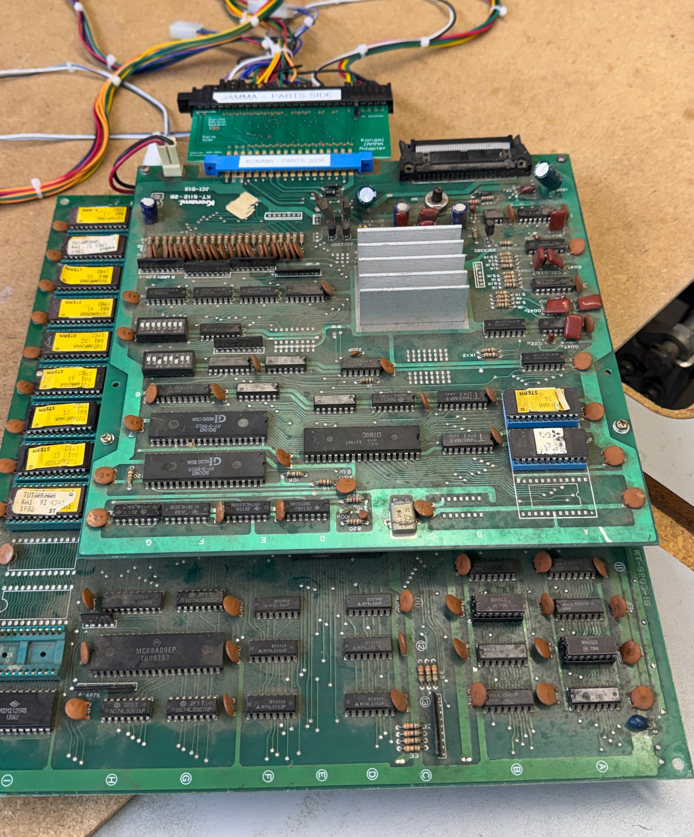
Board #1 – In for repair
Triage:
- Board reported to have graphics display issues
Once I got it all connected up:
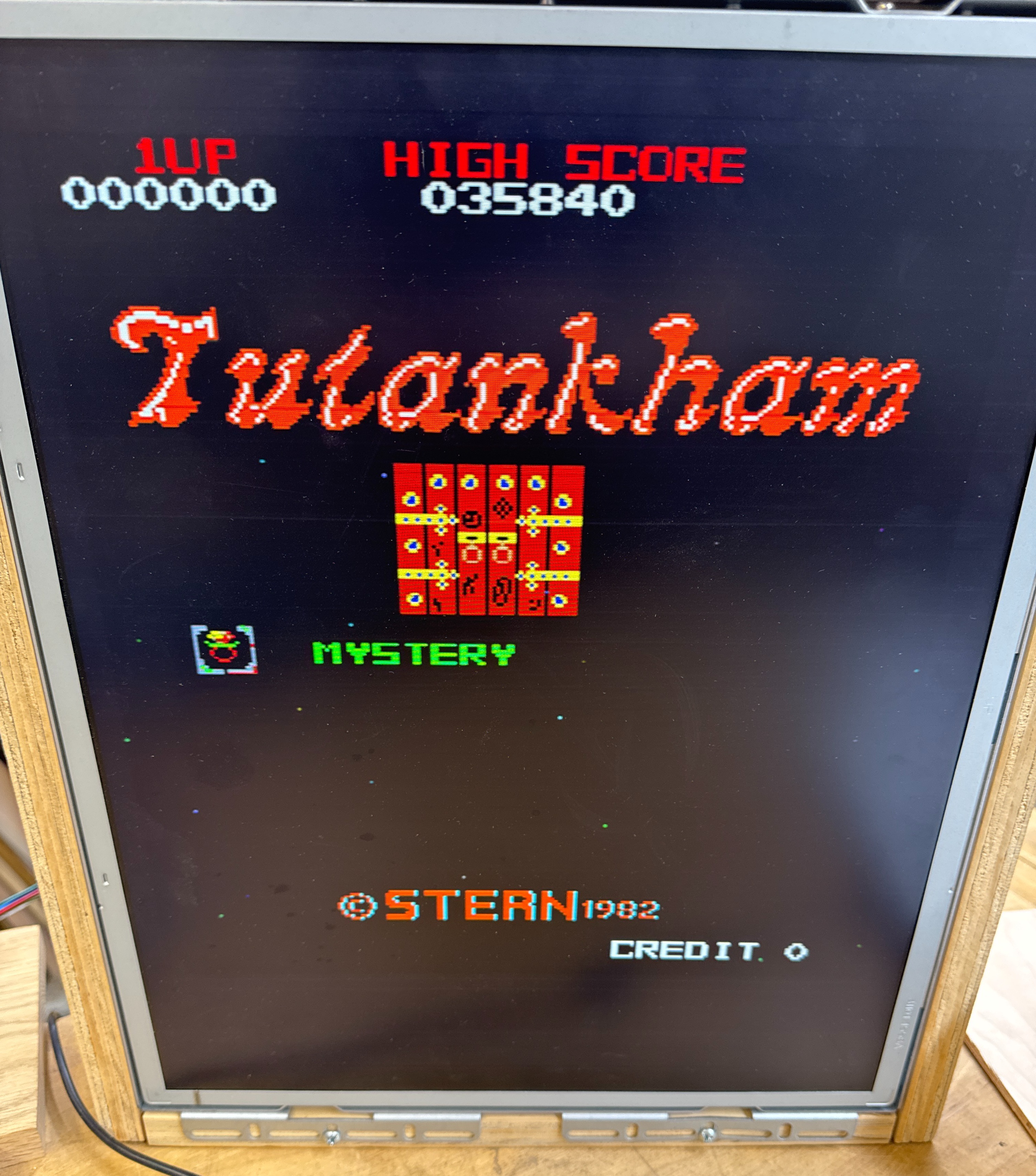
Notice the characters are bad, but the star field seems very clean.. I figured it was a logic issue when I first saw it.
I did spend some time creating a FPGA Catbox config to test all the RAM and ROM. It took a bit of time, but that all checked out. After that I spent time trying to figure out how the board worked and tracing the video signals. Nothing was really jumping out at me..
At one point I powered on and the video was ok(ish).. but then started to deteriorate over the course of a few minutes.. hmm.. Thermal? I broke out the can of freeze spray and hit a few chips..
Got to the 74LS240@A2 and everything cleared immediately! The LS240 just happens to control RGB outputs. Could it be that simple? (turns out no) Up until this point I had not run into 240’s – they must not be commonly used on Atari boards where I spend most of my time. So I ordered some. Popped in the replacement a week later – same exact issue.
Just for fun.. I hit the new one with the freeze spray and it cleared it up too.. really?!
At this point I checked everything in this area – resistors and all the ceramic caps.. Everything seemed fine. The 555 timer @D3 had an odd looking signal coming from it so I replaced it.. But that was not it.


Now I focused on these chips.. checking inputs, outputs, etc. All of the issues were here as it turned out.


Finally I found what was happening – Here is the video sync signal going into the LS367@C1 Pin 14 and the same signal coming out Pin 13. There are resistors there changing the output a bit.. But the key is that it is not getting to zero volts. Replaced the chip – same output.. hmm…

Then I determined the ground pin was floating at .8v when I measured it.. I thought maybe a leaky cap and pulled off the nearby ceramic caps, etc. There were only three chips that registered the floating ground and just over 4vdc on the vcc pin. At least I’m down to a small area on the PCB. None of that stuff checked out or made sense.

Fast forward a bit – I checked this every way and came to this conclusion: I found a design flaw in this PCB
The wide trace in the red outline is the ground plane that connects LS367@C1, 555@F0, LS04@E0. All 3 had the voltage issue. All of the ceramic caps and a couple of electrolytics around it were good. The problem is – this ground plane isn’t attached to the ground plane of the board. There are no traces on the parts side that were cut or missing – they never connected it. I connected a ground pin from this area to another on the actual ground plane with a mini-grabber during testing and fixed it all. Clean signals on the scope, vcc up at 5vdc where it belongs and the ground at 0v where it belongs.
I’m not an EE – but maybe the ceramics drifted over time and the video got progressively worse? The actual fix is the small jumper wire to connect the ground planes. Those three chip’s voltages all snapped into line and problem solved. The LS240@A2 that I initially hit with the freeze spray was outside all of this – maybe the cold was just enough to change the voltage/current or something to clean up the video? Not sure.
I was expecting some weird analog passive component issue – but this is a design issue IMHO. Once I found it and knew what to search for, there are a number of references to this game with graphics glitches and lines through the graphics.. Or just a star field and no graphics.. But I didn’t see that anyone to date had found the answer – this is it – add a ground wire.
Board works!
Board #2 – In for repair
This one came in reported with no sound and graphics issues. It put up a really good fight across the board.
However – to work on it.. it was very dirty.
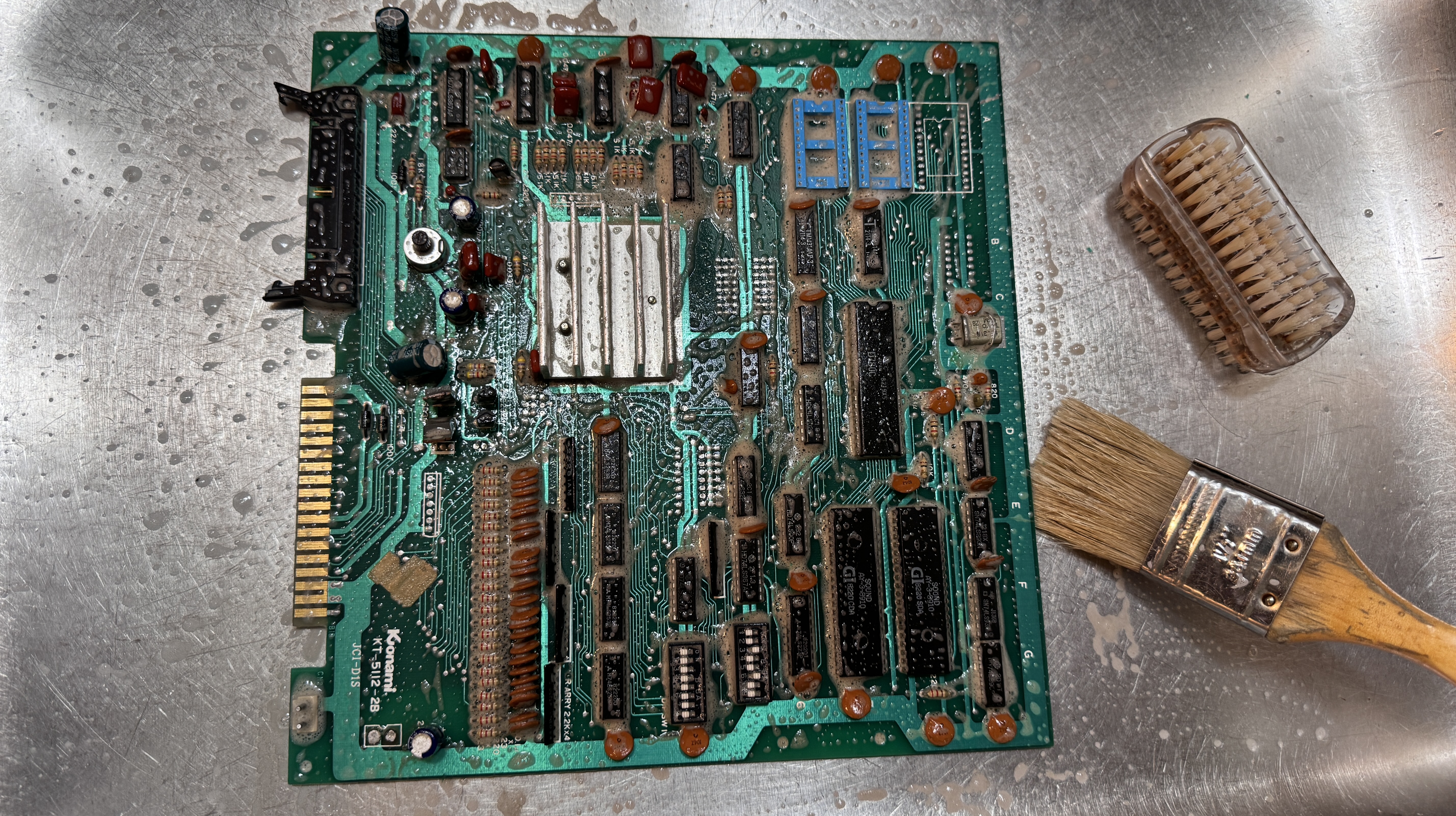
It got a bath before I could really do much of anything.
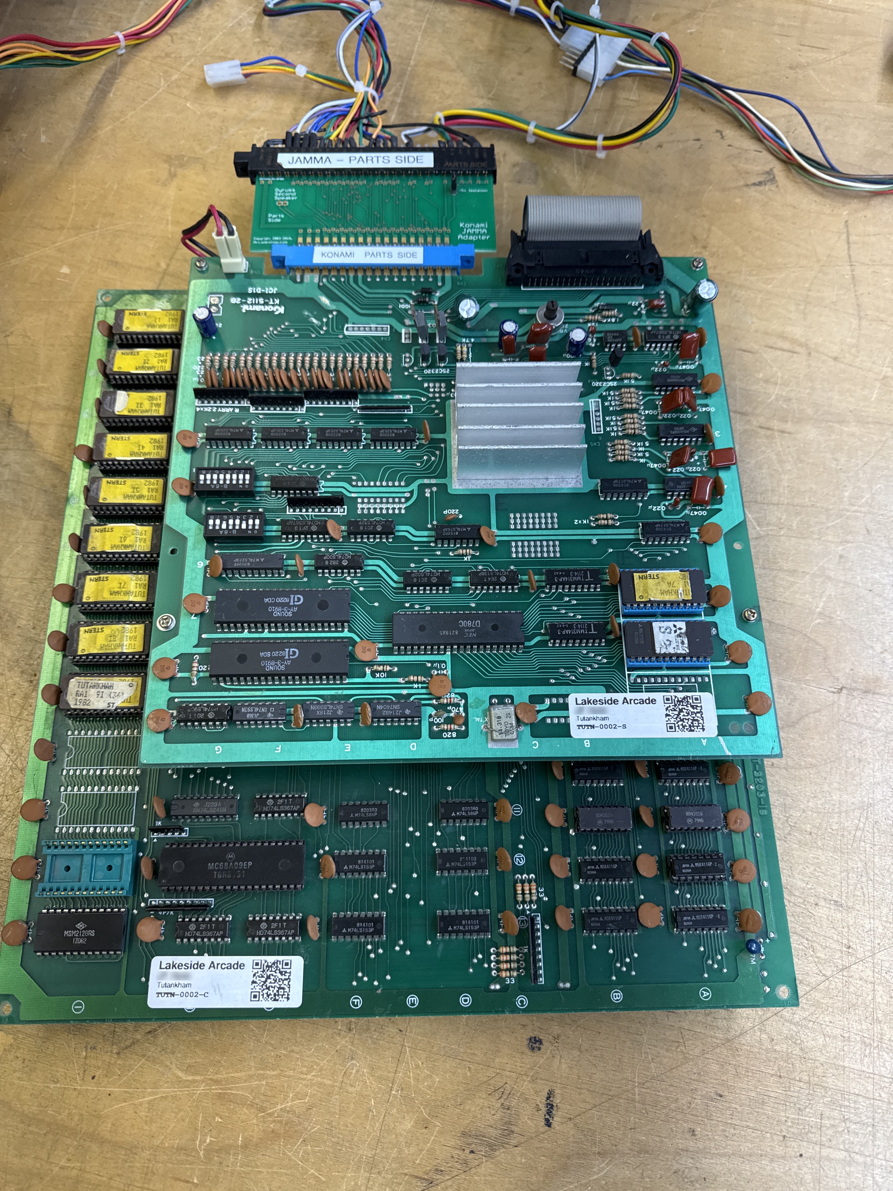
Much better.. at least the probes make contact now.. All of the socketed chips had been removed, got their legs cleaned, etc. I usually have custom bench adapters. Konami and PacMan are the only 2 left I use Jamma adapters for.. hmm.. maybe someday I upgrade..
The game did have some serious graphics issues. I don’t think this is what the owner saw.. More on that in a bit.. The sound issue I resolved using my Audio Probe which makes hunting down those issues much simpler. Sound board needed a new amplifier.
After that this board put up a really good fight. I’d created as Catbox config from the first one I’d worked on and had to remove and socket the 68B09 CPU. Once connected I found a bad ram and replaced it.. You would think it would have been that easy.. Ran it overnight and it had failed. Retested and and it showed a failed ROM. But it was a socket.. Tested again.. another failed ROM.. It was obvious the green sockets were all flakey.. I replaced all of the on the graphics ROM side. The flakey sockets were causing the majority of the graphics issues.
Ran it overnight again and the board failed. This time I narrowed it to a Konami 083 custom chip. Which I do not have any spares for.. A repro is made, has to ship from Italy and is $80+ .. I was able to source a parts board and salvage one 083.. around now is when I kept running into reliability issues and swapped in another RAM chip..
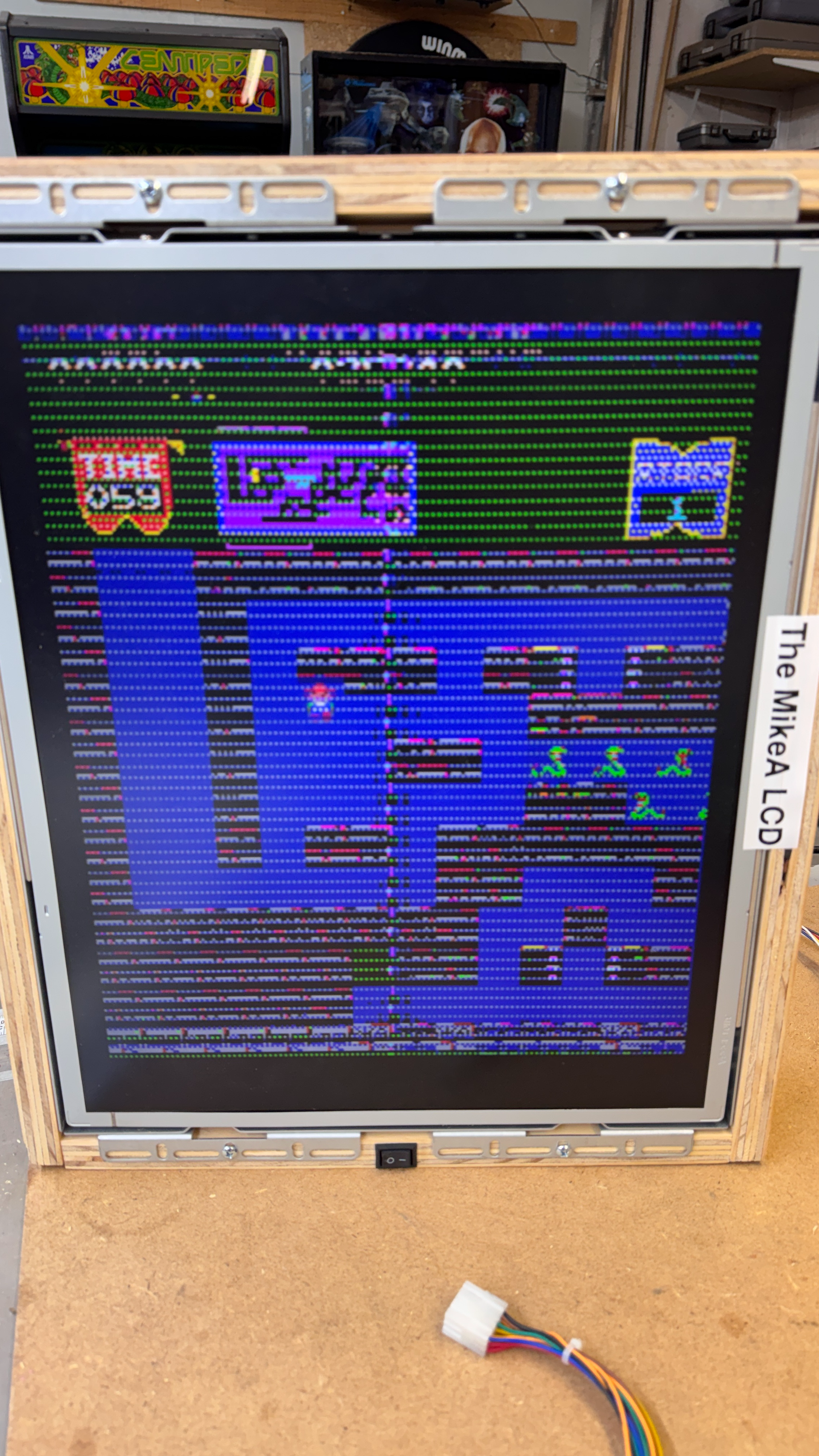
The last big item turned out to be a combination of not knowing the game very well, an issue on the board itself and MAME being inconsistent with the actual game and an adjacent ‘sparkle issue’.
If you look closely, there are dots on the title screen.. While testing.. I had issues with sparkling graphics that just turned out to be low voltage. This stack really wants 5.0v on the chips, just turning it down to 4.8 and some of the graphics were sparkling a bit.. The issue with the dots they would cut in and out it took a while to find the pattern..
Pressing on the board would make them appear, disappear, voltage had no effect. But they were really consistent in their placement which made me think it was software based. I powered up MAME and no sparkles.. Hmm.. after messing with this for far too long and a few false positives on other sockets, wiggling the 084 custom @3F caused the patterns to cut in and out.. It had the last of the green sockets. I replaced it and now the sparkles were 100% on. No getting them to go away.. As a rule.. doing stuff the hard way comes easy.. Had I looked sooner.. the 084 Konami custom is a Starfield generator..
- Bad socket made it cut in and out
- MAME made it look like the sparkles were not supposed to be there
- Had prior voltage issues with sparkles in graphics
- Probably should have found a video to verify, but I though I was chasing a too many sparkles issue – not a “should have” sparkles issue.
Board works!
