
*** Newest Entries always added to the bottom ***
Visited a buddy on the west coast and helped get his Battlezone cab up and running. (wow.. this was years ago….)
We did a fair amount of work to the cabinet, got the monitor functioning, rebuild the controllers and replaced missing parts.

Once we got the game up and running, it looked pretty good. Then the bad vectors started.
Over the course of a few hours, this devolved into no test screen and a couple of random vectors now and then. We determined that some jumpy 5v voltages were coming off the ARII and set it aside.
Once the parts came in (2N3055, LM305 and while we were at it – the TIP32) – replacing them cleaned up the bad power. Still no joy on the vectors however. After some remote coast to coast diagnostics – the boards were packed up and shipped to me.
I’ve never worked on Battlezone – but there is a first time for everything.
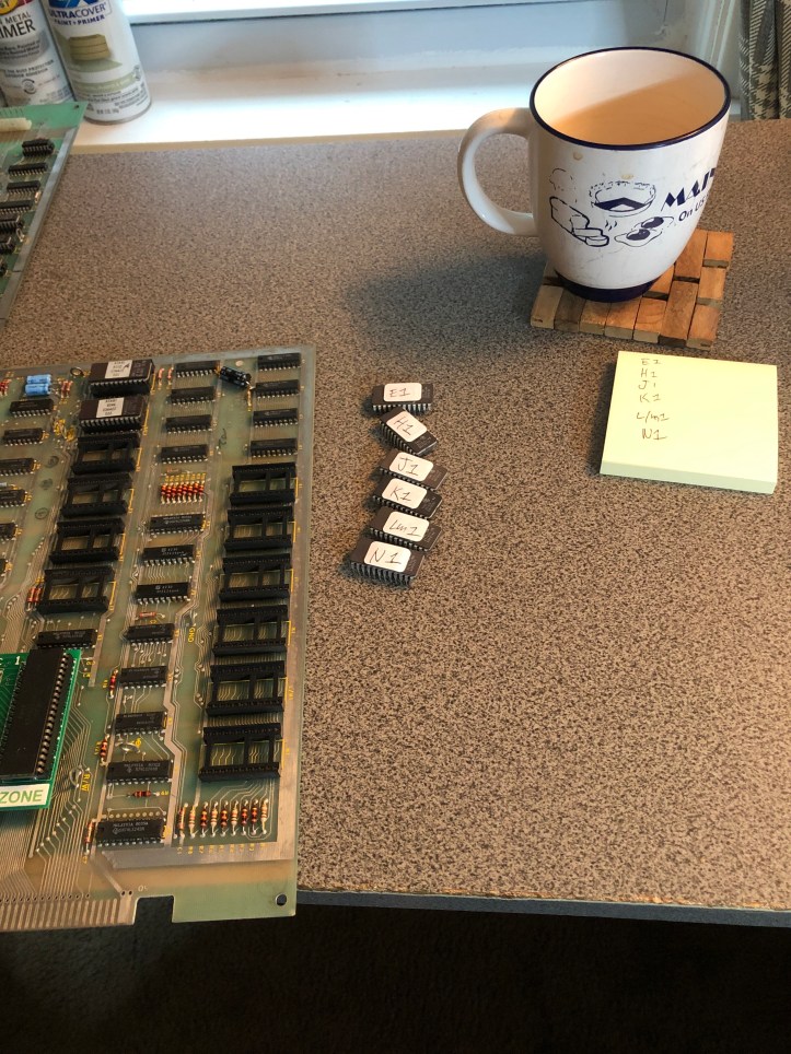
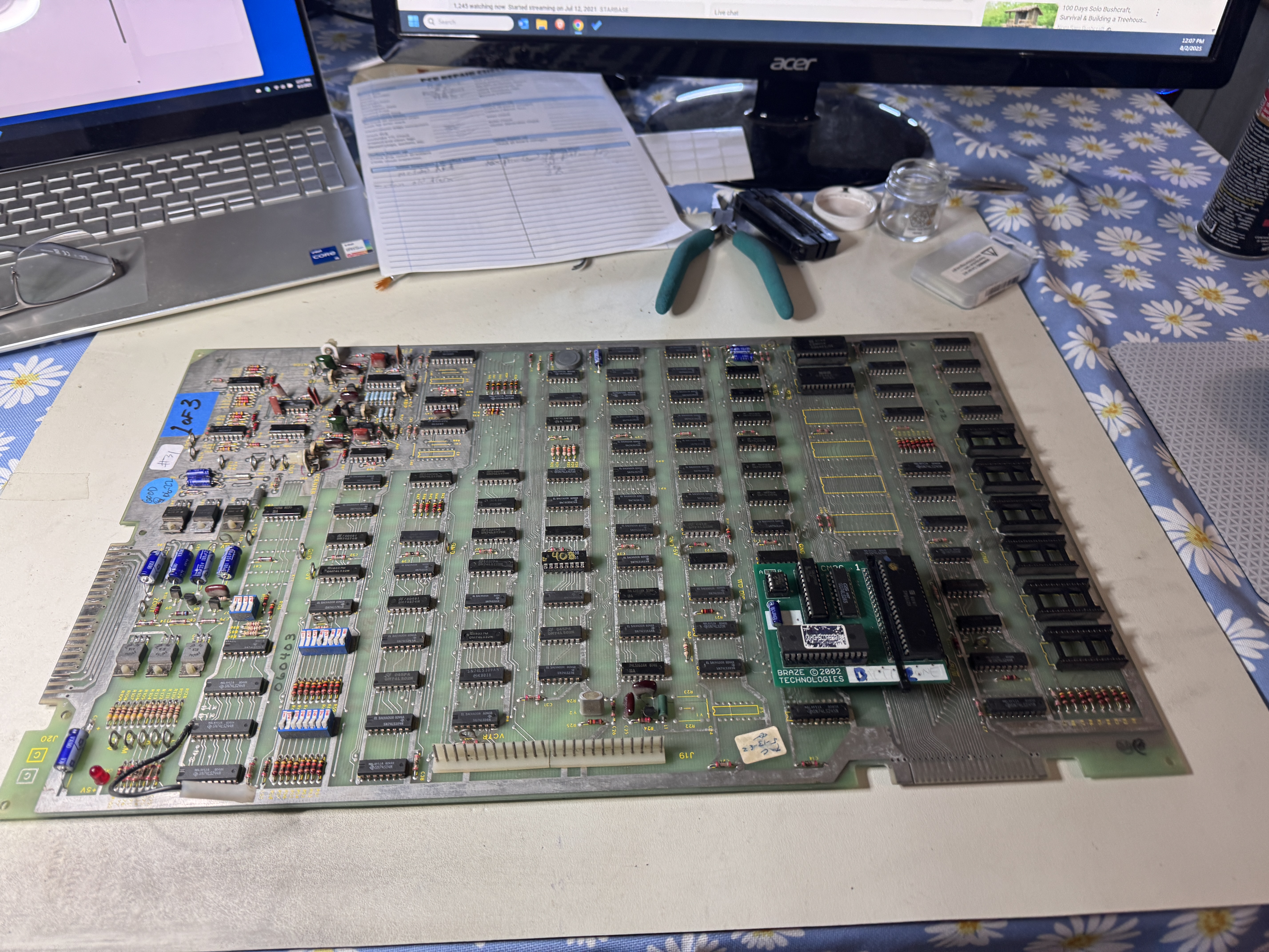
The Braze kit is supposed to keep things simple, but I burned a set of EPROMs so I didn’t have to deal with the daughter board. Goes great with the morning coffee.

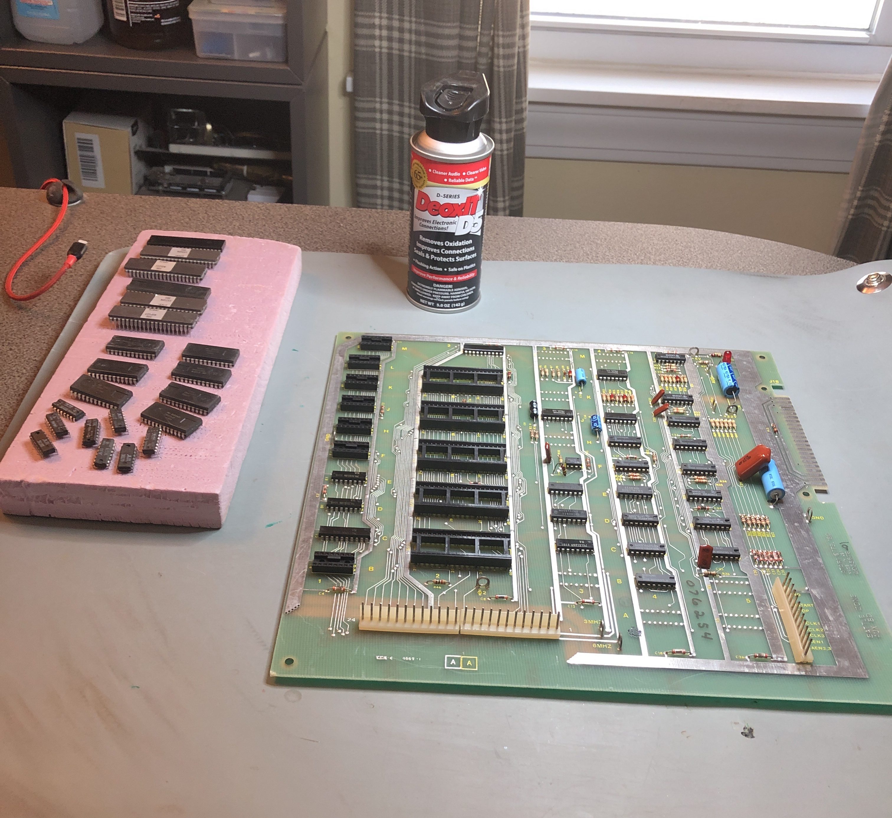
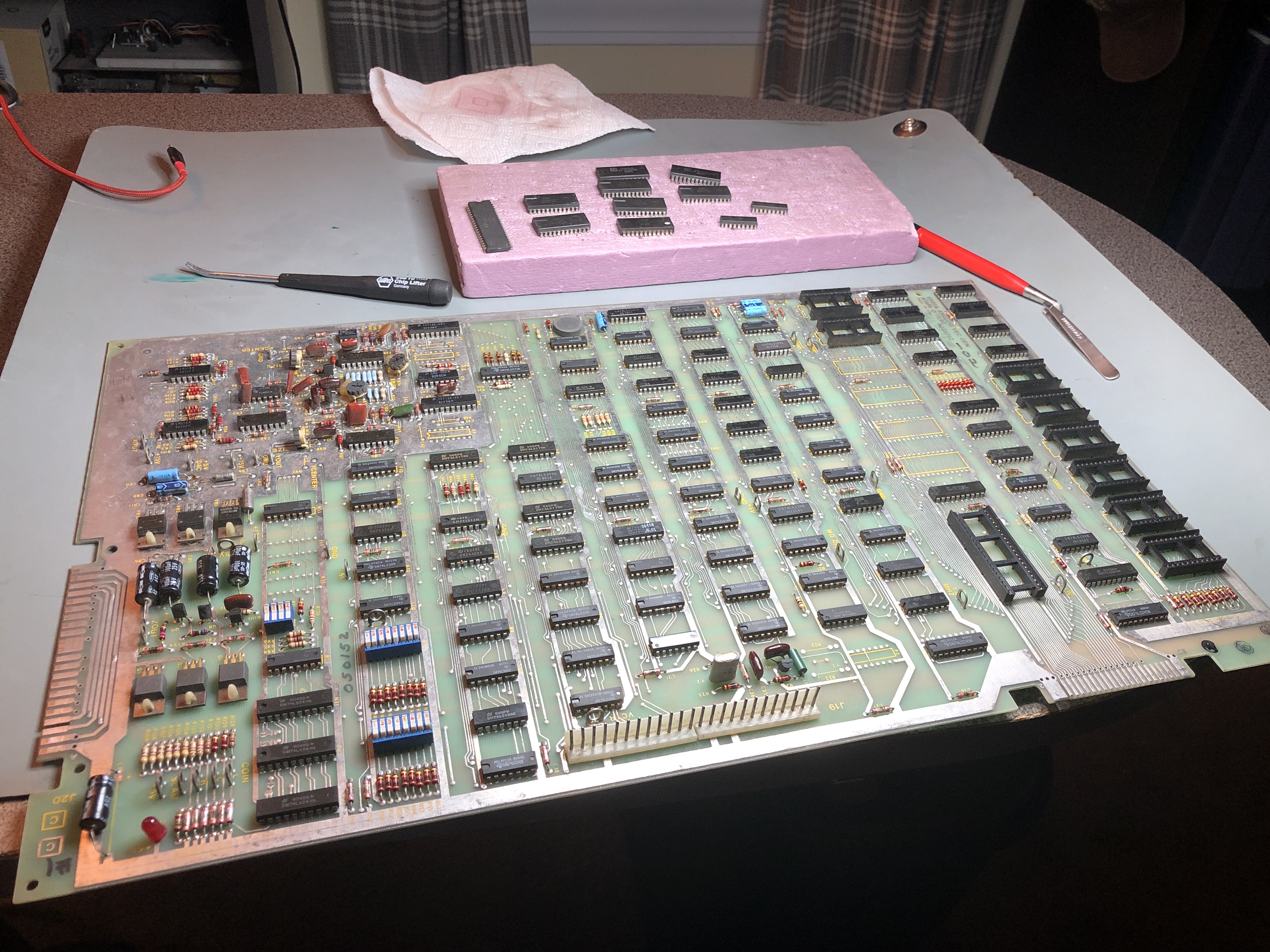
Even though this board was mostly working – I pulled all the socketed chips, cleaned the legs, verified the vector ROMs and the proms. No need to be chasing a software issue. While it was all apart – it got a good cleaning and Deoxit all around.
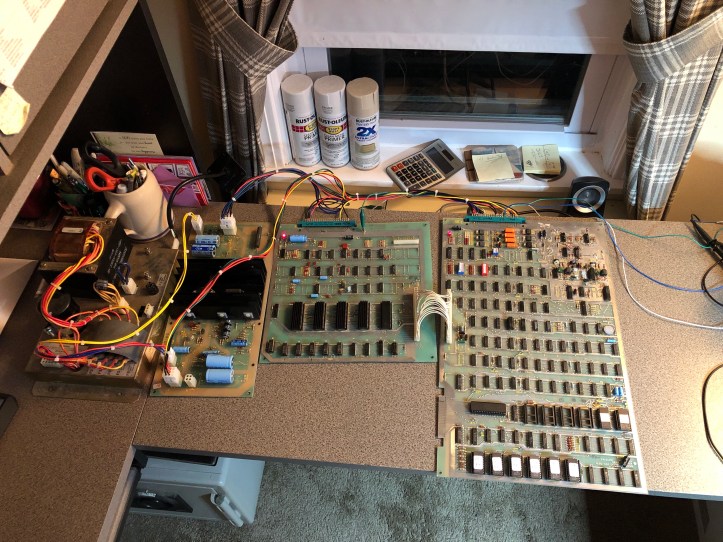
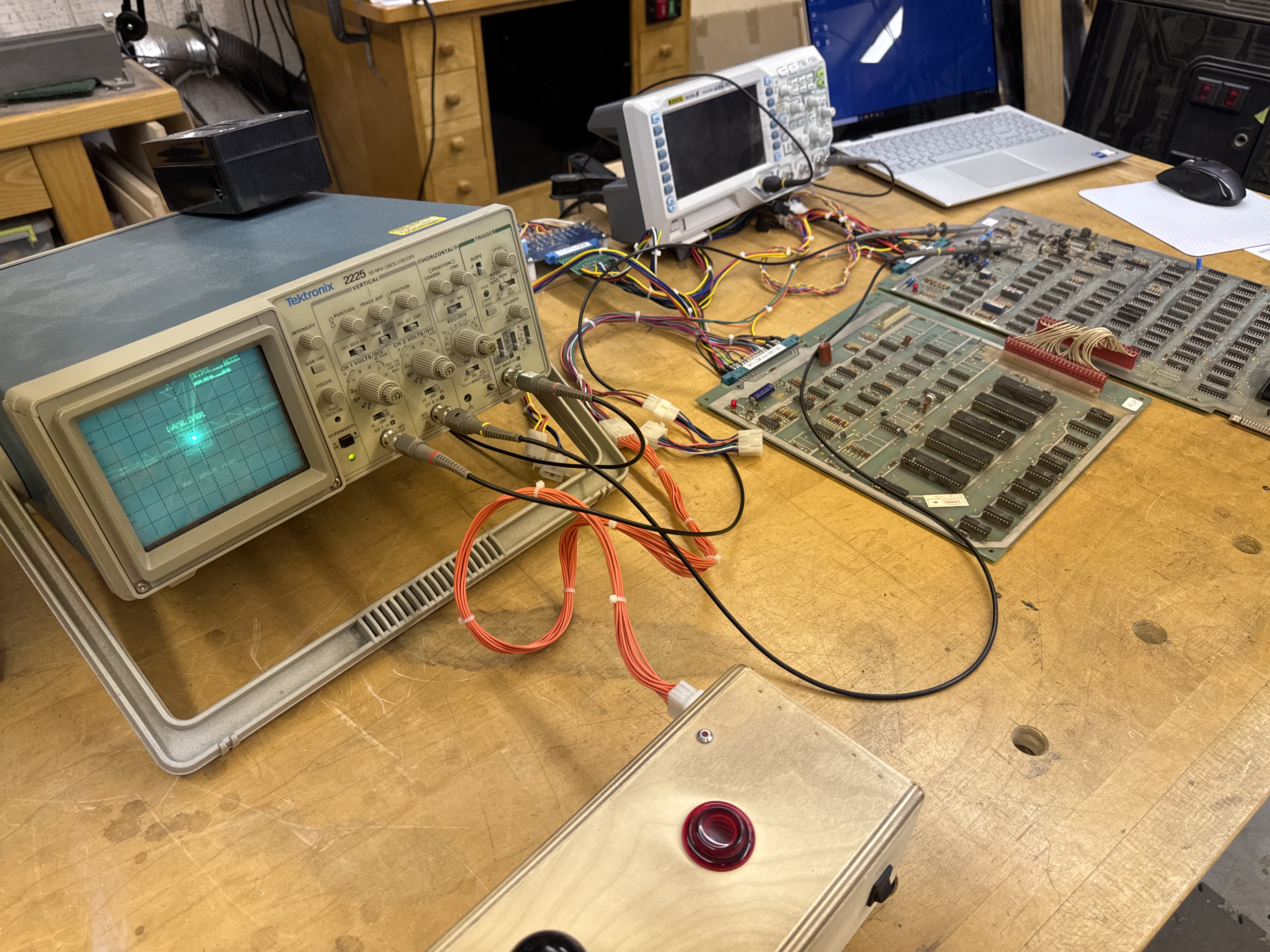
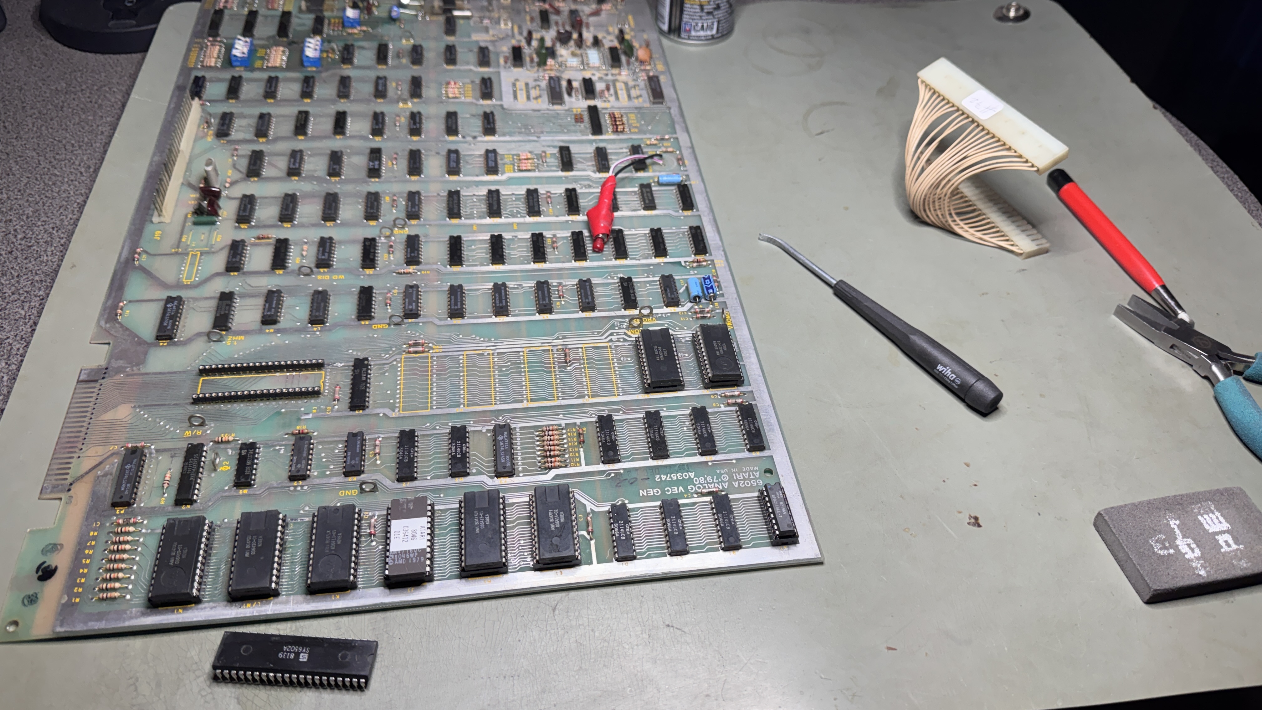
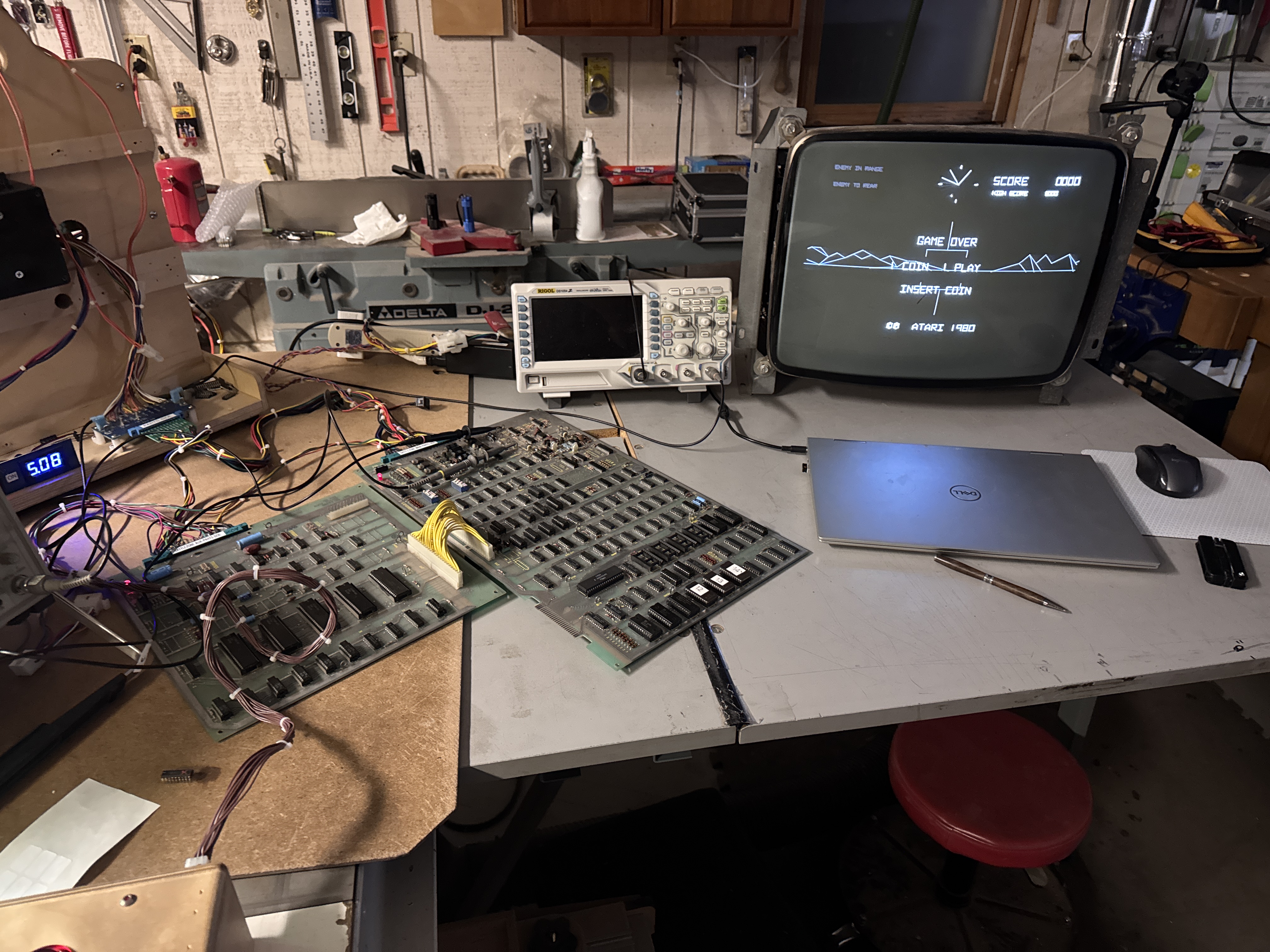
Most of my board work to date has been with simple Jamma adapters and a small Jamma tester. I’ve also done a few Sega G80 sets – but the bench harnesses were relatively simple. Here I put together my first real custom harness for an Atari stack. I received the boards and the ARII from my friend just so I could confirm the ARII was good. The power brick is from my Centipede and is basically identical to the Bazzlezone one.
I got it all hooked up with Molex using18G wire on the power side and 22G on all the data lines. After getting it set up and checking voltages and double checking all the pinouts, the boards powered up with no issue. Nice clean 5v. All the other voltages were good at the board level.
I spend considerable time learning how this board worked. A couple of links helped.
The Secret Life of Vector Generators and Battlezone Disassembly
A lifetime ago I was pretty good at 6502 assembly language, but these guys did a great job documenting the code. Between understanding the theory of operation, looking at the actual Bazzlezone code following along in Mame.. I was able to get a better idea of how to approach the issue. Over time….

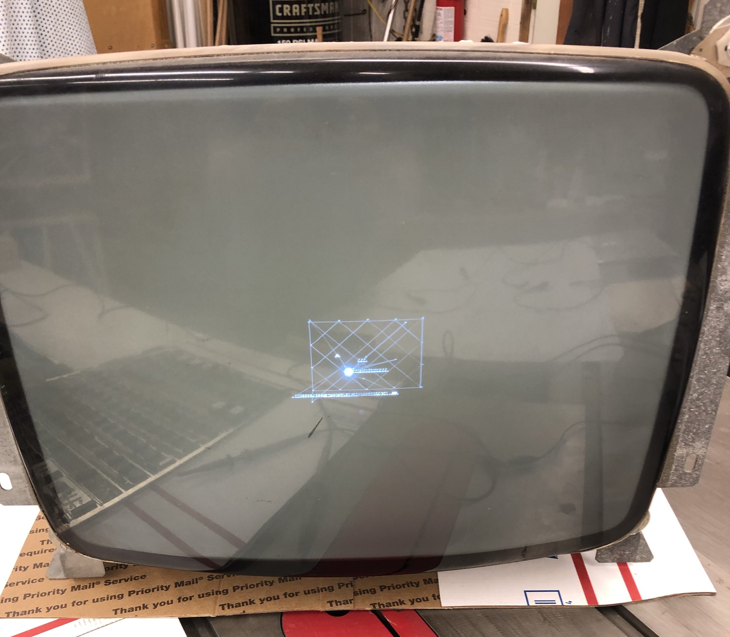
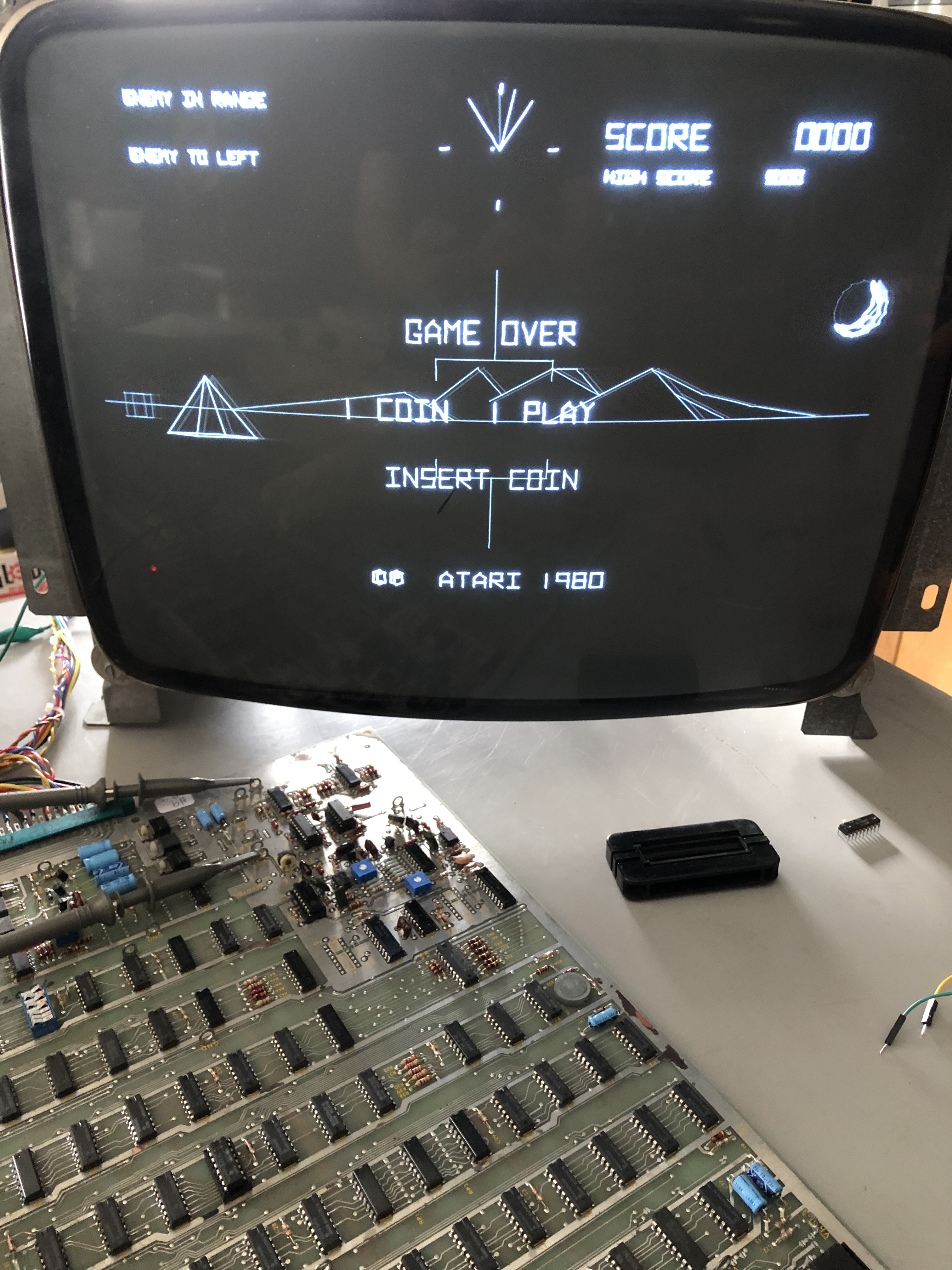
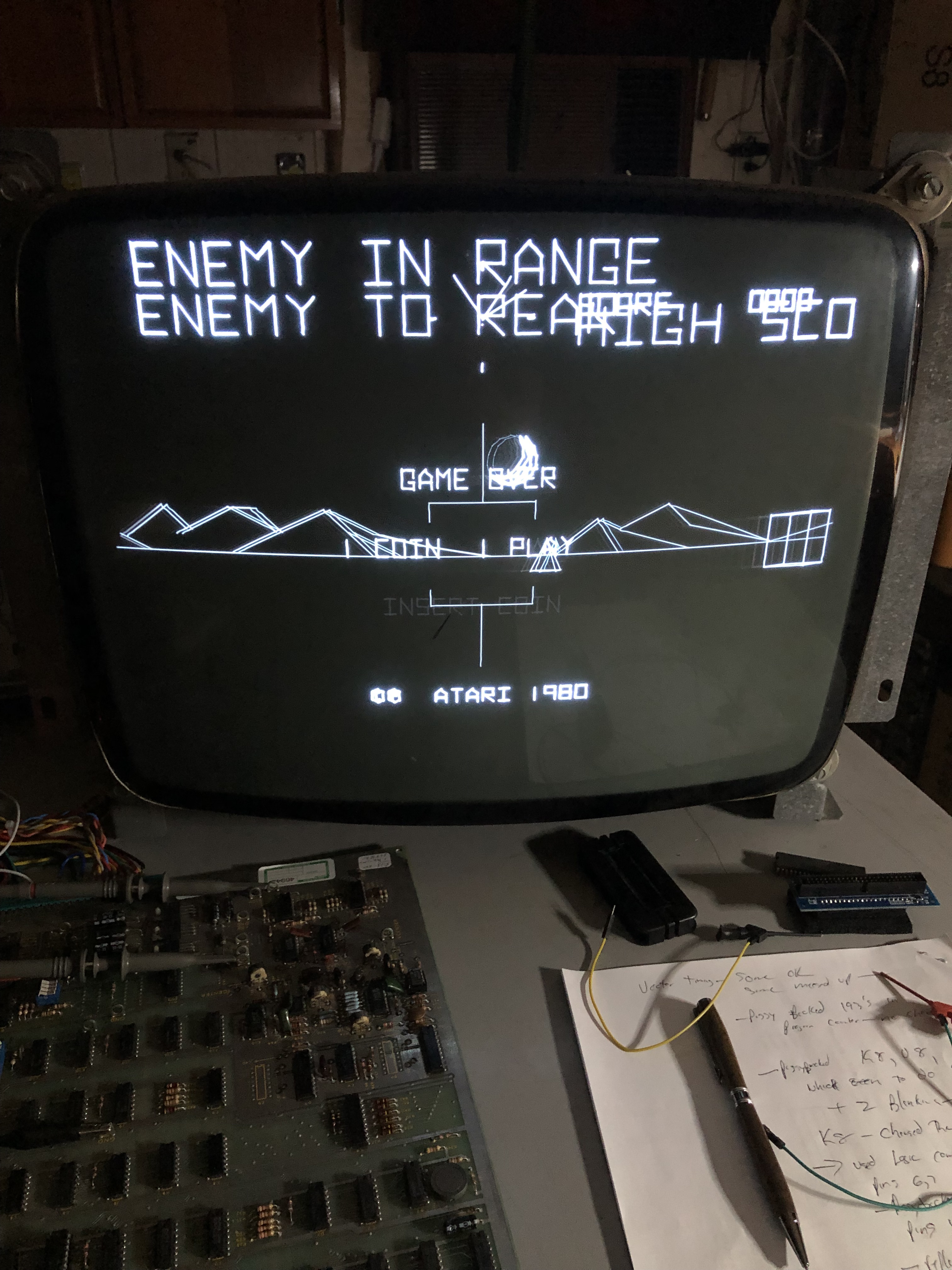
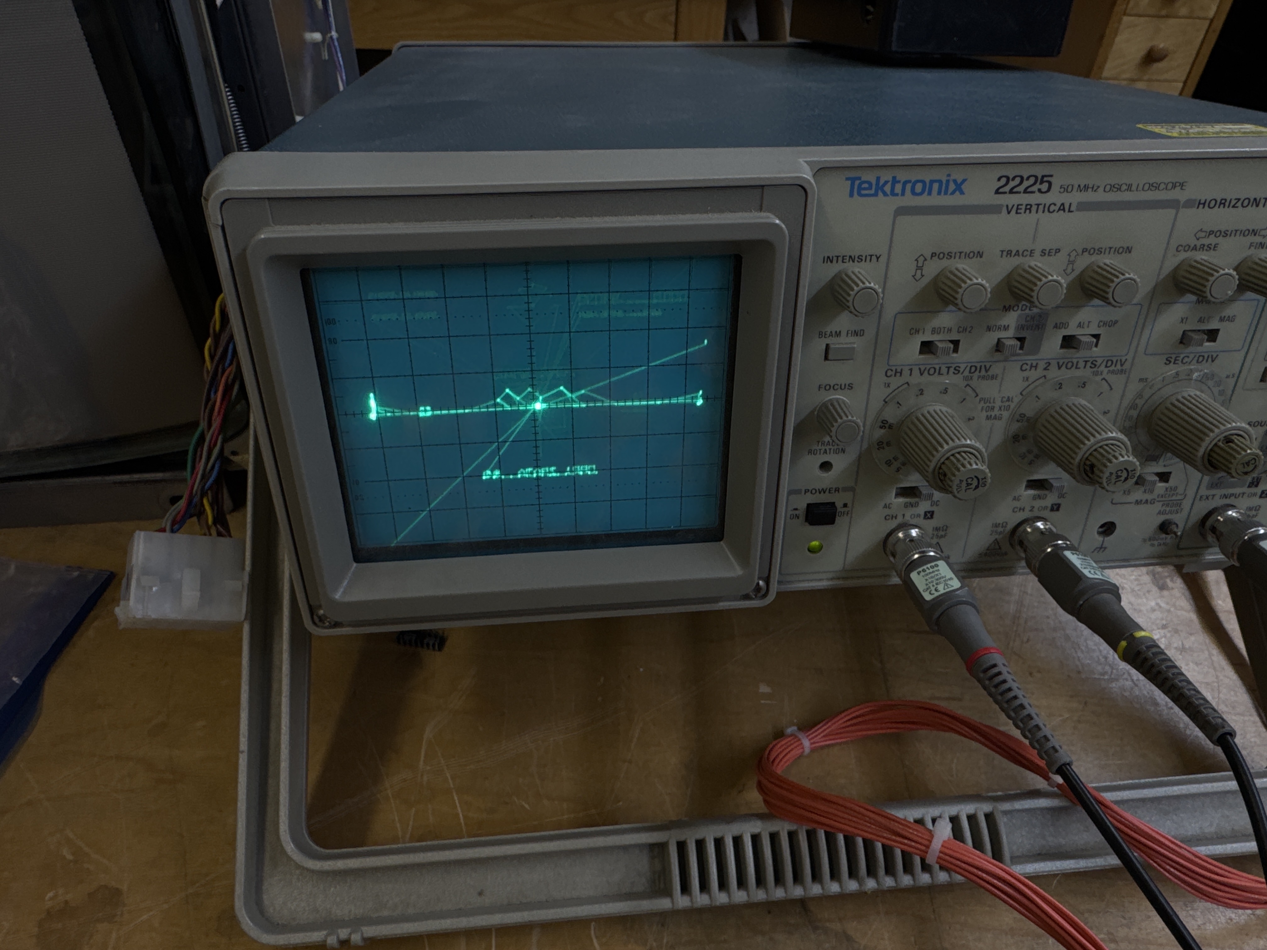
Here is what I started with in game mode (game played blind). I couple of errant vectors. If I switched to self test the screen would be blank.
My initial diagnostics focused on the analog output section of the vector generator board. Since it would be the likely source of issues.
I did a little maintenance first – the TL82’s at A10 and D10 were beat up and their sockets were a mess. They had tiny caps soldered to pins 1,2. A replaced the sockets and put the caps on the solder side of the board. In the future – the TL82’s will be easy to replace when they fail. My ROM set watchdogged immediately. Swapped the Braze kit back in and everything started working. I thought my ROMs were bad. Retested them, all good. After messing with it for a little while – I bent the legs in on the CPU. Problem solved. The CPU socket is all stretched out from the machine pins of the Braze kit. I’ll likely replace the socket even though the Braze kit will be in the final setup.
There were a couple of existing machine pin sockets, I removed them and put in dual wipes. A couple of signals were flaky on those sockets.
A spent time chasing signals in the analog section without success. I swapped in different DACs and analog switches. No difference. Basically – very little in terms of signals was coming into the analog section on X lines and just about nothing on the Y lines.. This part of the board did get cleaned up quite a bit, but it was not the cause of the problems.

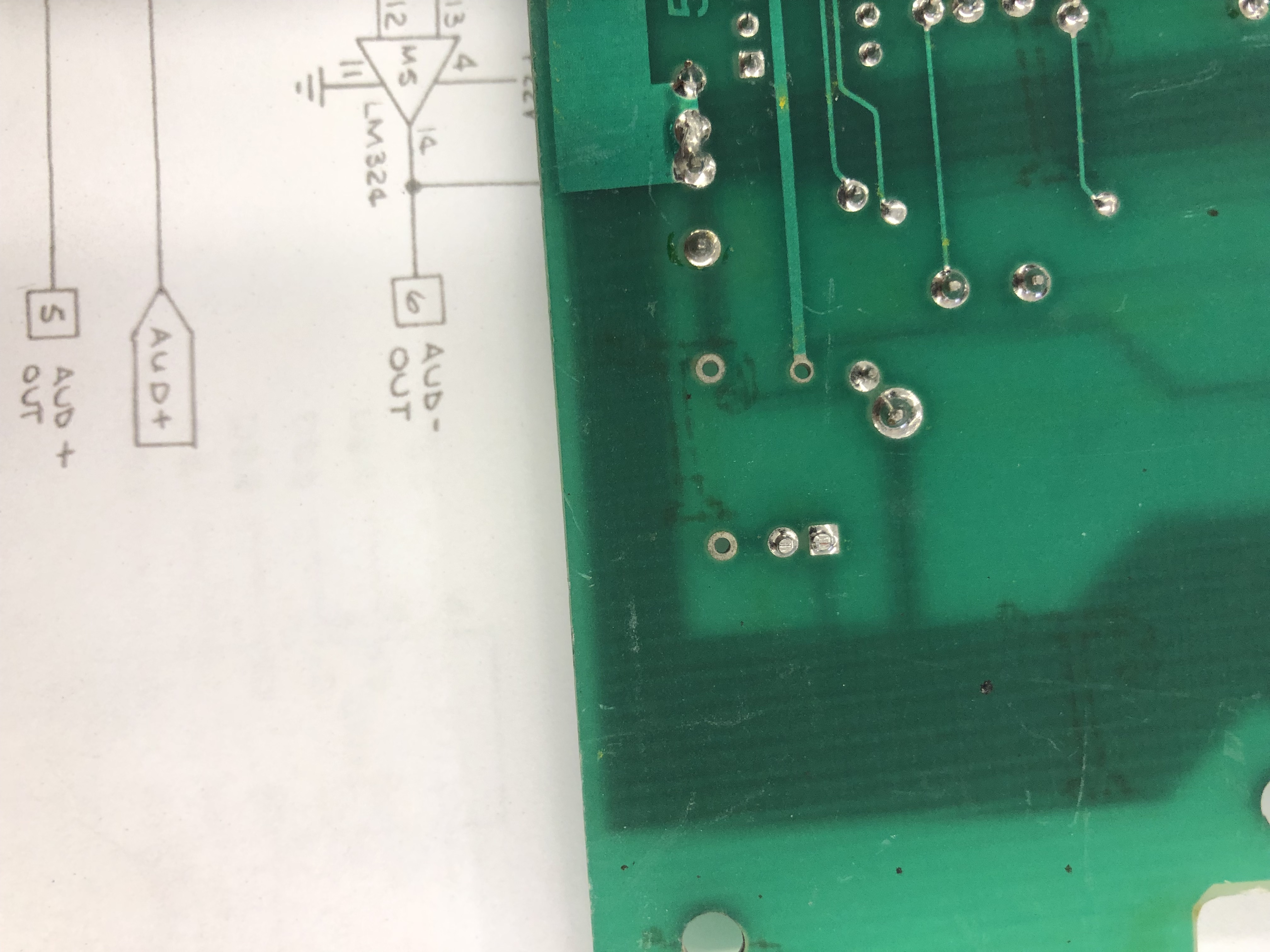
My simple sound amp.. A speaker, little 9v amp and a connector. It works with line voltage or amplified audio it seems and plugs into the AR or I can connect it to the PCB It’s no Bose system, but I can hear the beeps. I’d get one small low tone. Turns out – that’s what it does when all is good with the test switch on. I could coin the game, start, fire guns, etc.. so everything was fine there.
While poking through Mame I discovered ‘diagstep’ which is technically a button that would be on the coin door, but the schematic doesn’t show it. Mame has it and I tested it on the board stack. It would also generate a few bad vectors. The part that later proved helpful is that diagstep generates one vector at a time. It showed the vector generator engine was at least partially working.
It takes a while to learn a new board. Its even tougher when you don’t have another to compare it to. I had read about vector generator engines, but the ‘ah-ha’ moment was when I considered it completely different machine inside the primary one. I’ve repaired a few Gyruss boards – they have 2 CPU’s sharing the work. This stack is the same idea – except one CPU, the vector engine which behaves like its own CPU with a limited set of instructions and of course the mathbox which in itself is yet another machine in a way.. A lot has been written on diagnosing vector boards – but until you are actually working on them. You don’t really know. There is no substitute for actual experience.
Once inside the vector generator, its a big circle. The on ramp is the LS245 at F2. I spent some time there making sure the bits were going in and out as they should. They seemed to be.
Next I put the board in test mode and piggybacked RAM – just to see if anything different happened. I could get the tests to fail now and then, but I’d clean the legs and they would clear. I was pretty confident all the vector ram was good w/o removing, socketing and testing them. The source code showed a pretty good ram test pattern was used. However – the vector generator was acting as though it was crashing (it was really). But ROM and RAM were good.
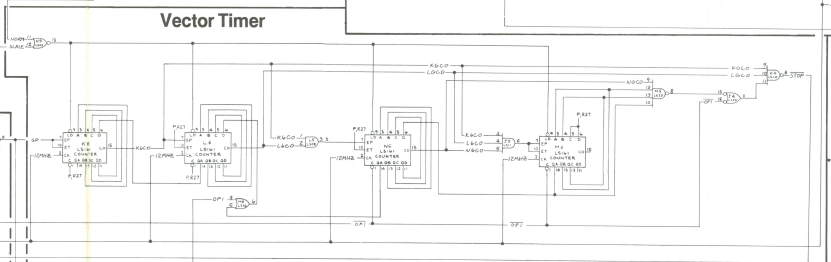
Again – if I had a board to compare with – this would have been simpler. Address line AVG6 and data line DVY6 is where things appeared to fall apart. I spent considerable time looking at the LS193 counters at E5, F5, H5. F5 is where the activity fell completely off. I happened across a very simple test. It checked the output side of the counters with the scope and hit the reset button – I got nice clean counts. I went down the count chain and hit reset every time and could seen clean signals. They seemed to be good. In fact – I used reset quite a bit in testing. It showed parts of the circuit running for a second – and then ‘crashing’ for lack of a better description.
I backed up a bit and tested the LS367’s at F7, H7. Both seemed to be running correctly. Where was the circle breaking down?
I did a lot of piggybacking and testing a lifted chip leg on many of the select lines. I have a logic comparator and that got work too. Its pretty useful – but the readings are tricky sometimes.
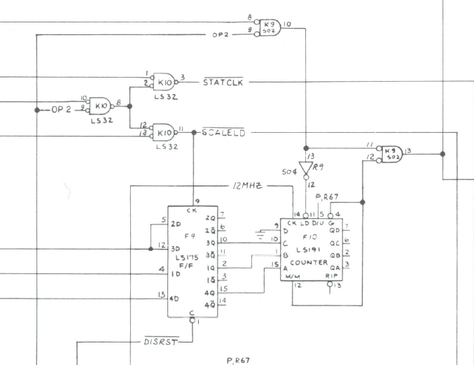
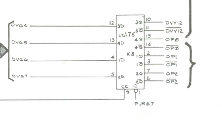
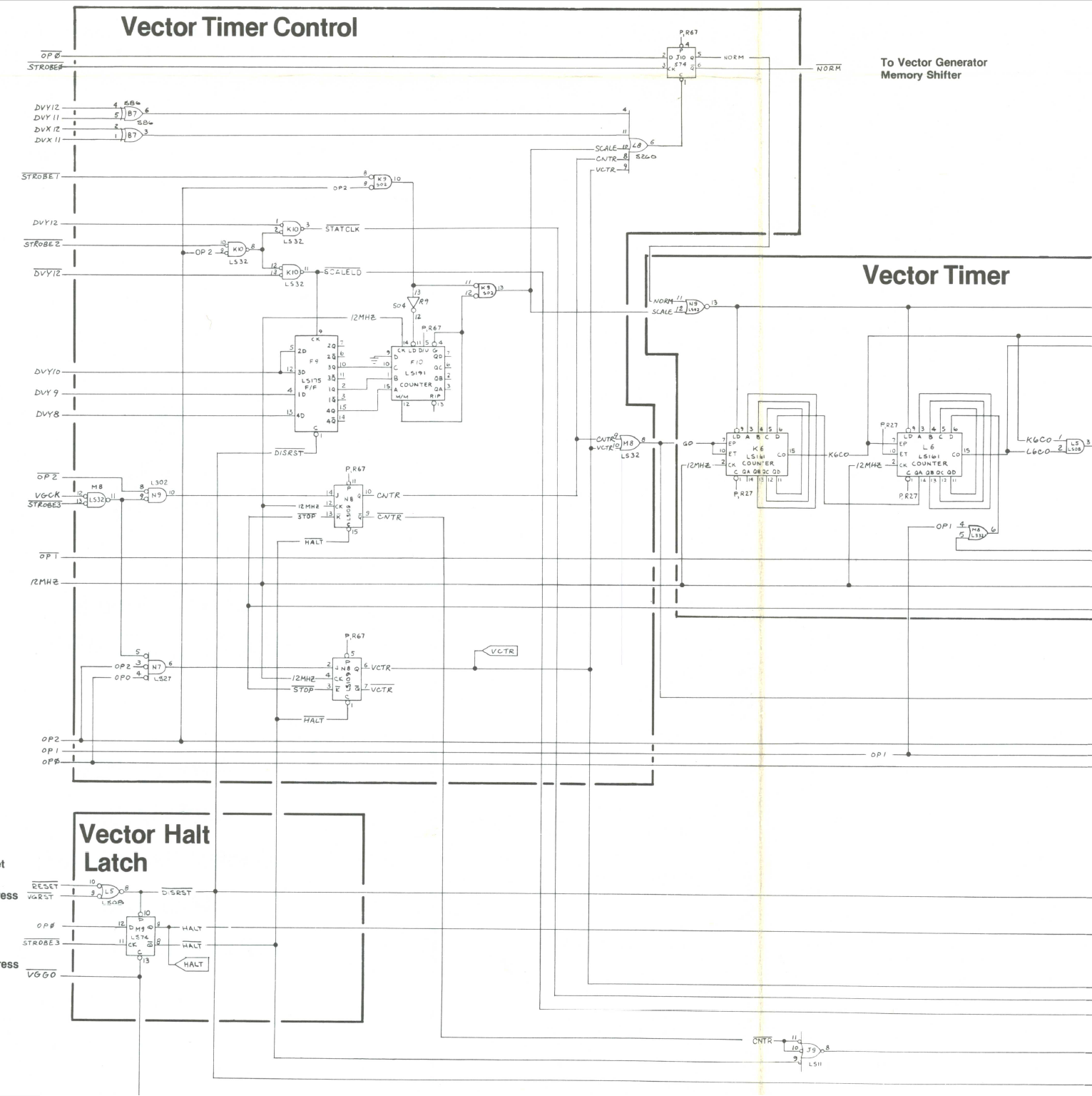
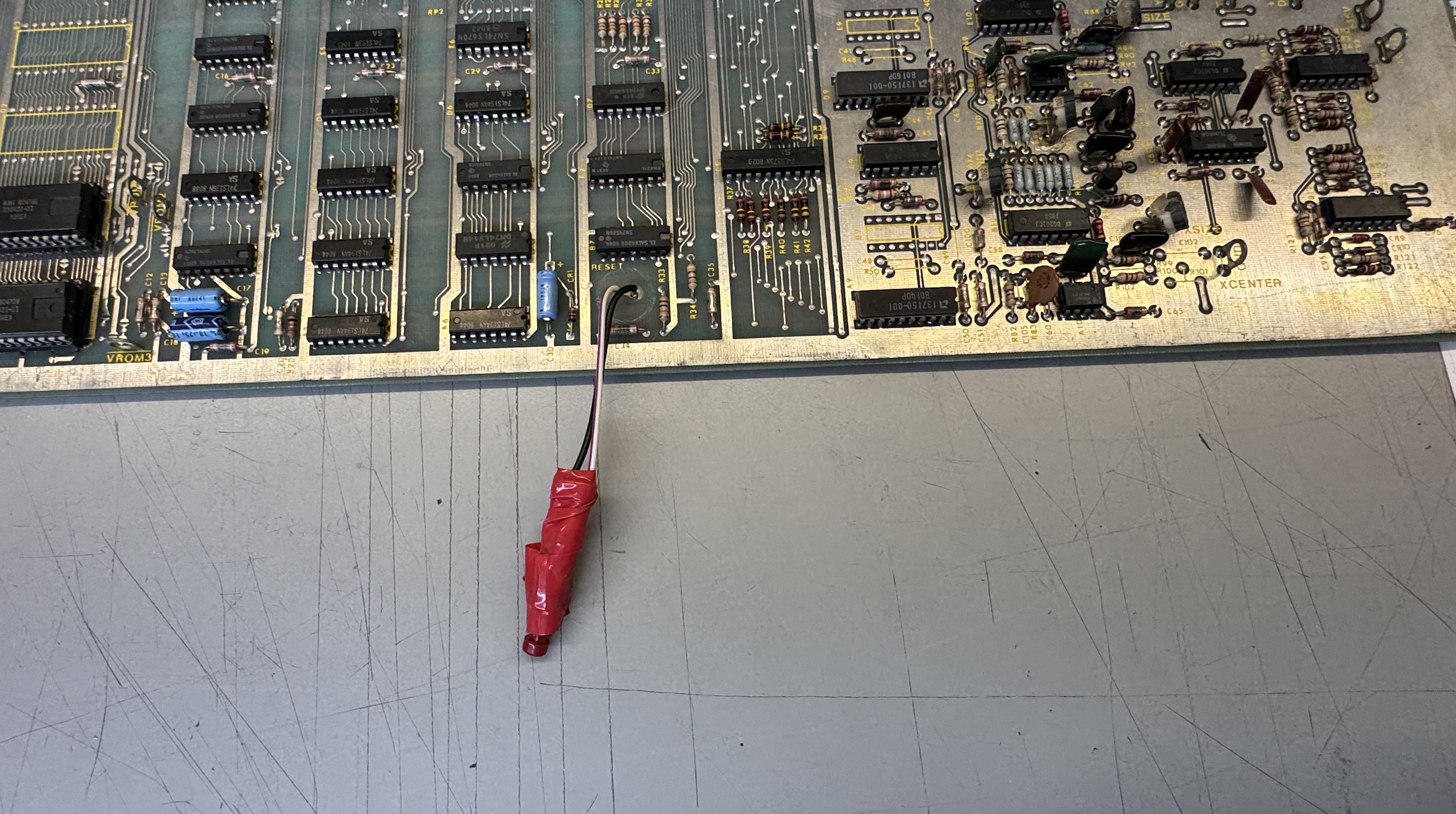
After checking may different parts of the state machine, vector timer and data shifter. This part just didn’t seem right.. The OP2 signal would sometimes come in, but STATCLK and SCALELD and the 191 counter at F10 was doing very little.
All of this brought me back to K8 – again.. I had been there a number of times.

I put the logic comparator on it and the LED’s were solid on pins 5,6,7. But not conclusive.. Not even sure why it would light up pin 5, it’s an input.. Next I piggybacked the chip and lifted the leg on pin7. I was getting the same signal as the real chip (it seemed) when I moved the probe back and forth.
One last idea because I really didn’t not trust this chip – I used a second probe and tested the lifted leg output vs. the actual one on the scope. (I wish I got a picture of it) Most of the signal was the same but one part was different, just enough that I pulled the chip.

Well that was discouraging. It checked good. But I still didn’t trust it and put a new chip in anyway.
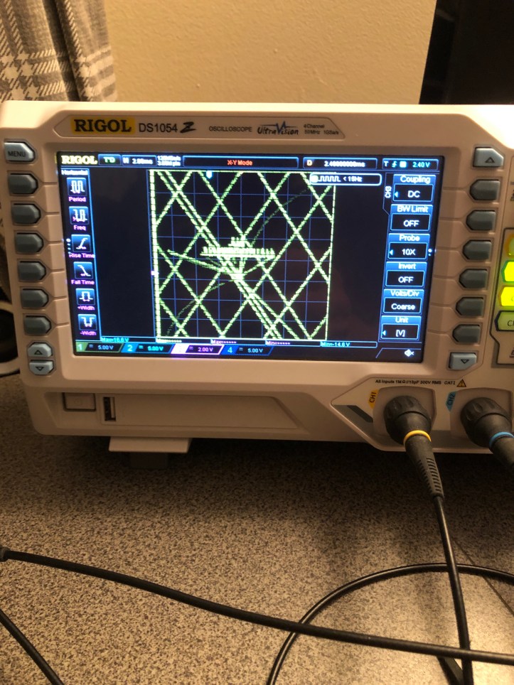
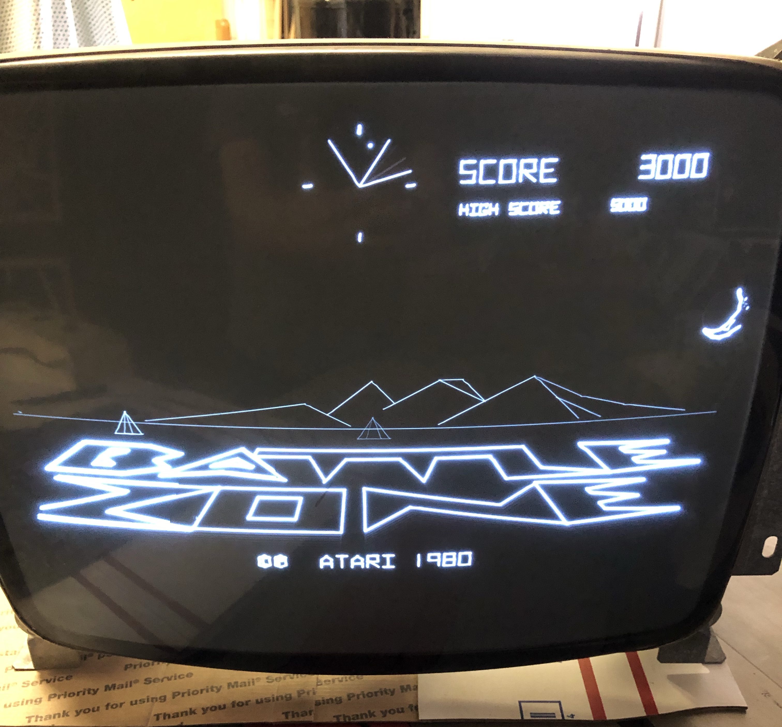
And just like that the vector generator sprang to life! I’ve run into some borderline chips in the past – but this particular one is easily the most borderline. Seeing the vector generator work – now everything in the circuit makes more sense.

Next step was to wire up my harness to connect to my G05 bench monitor. But I had a small accident before I got it hooked up. I accidentally grounded the -22v line and blew up a bunch of stuff.
- 2 Diodes on the ARII – I replaced all 4
- 4A Fuses on the power brick
- 7915 regulator in the analog section
- Both AM6012 DACs
- Both TL082’s
It was the slightest tap – but took out a bunch of stuff.. ughhh. Another experience point.
There seems to be something going on in the analog section..
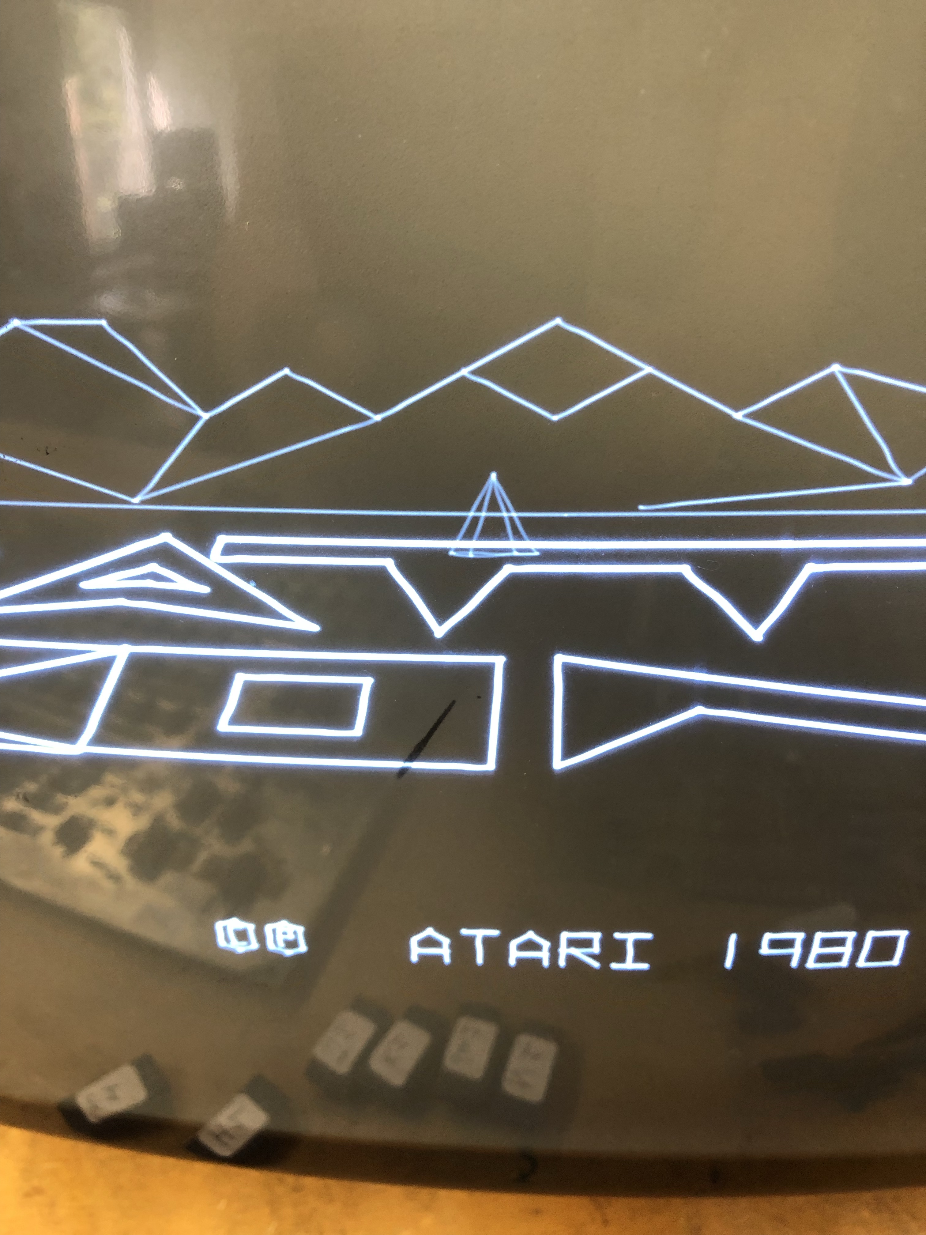

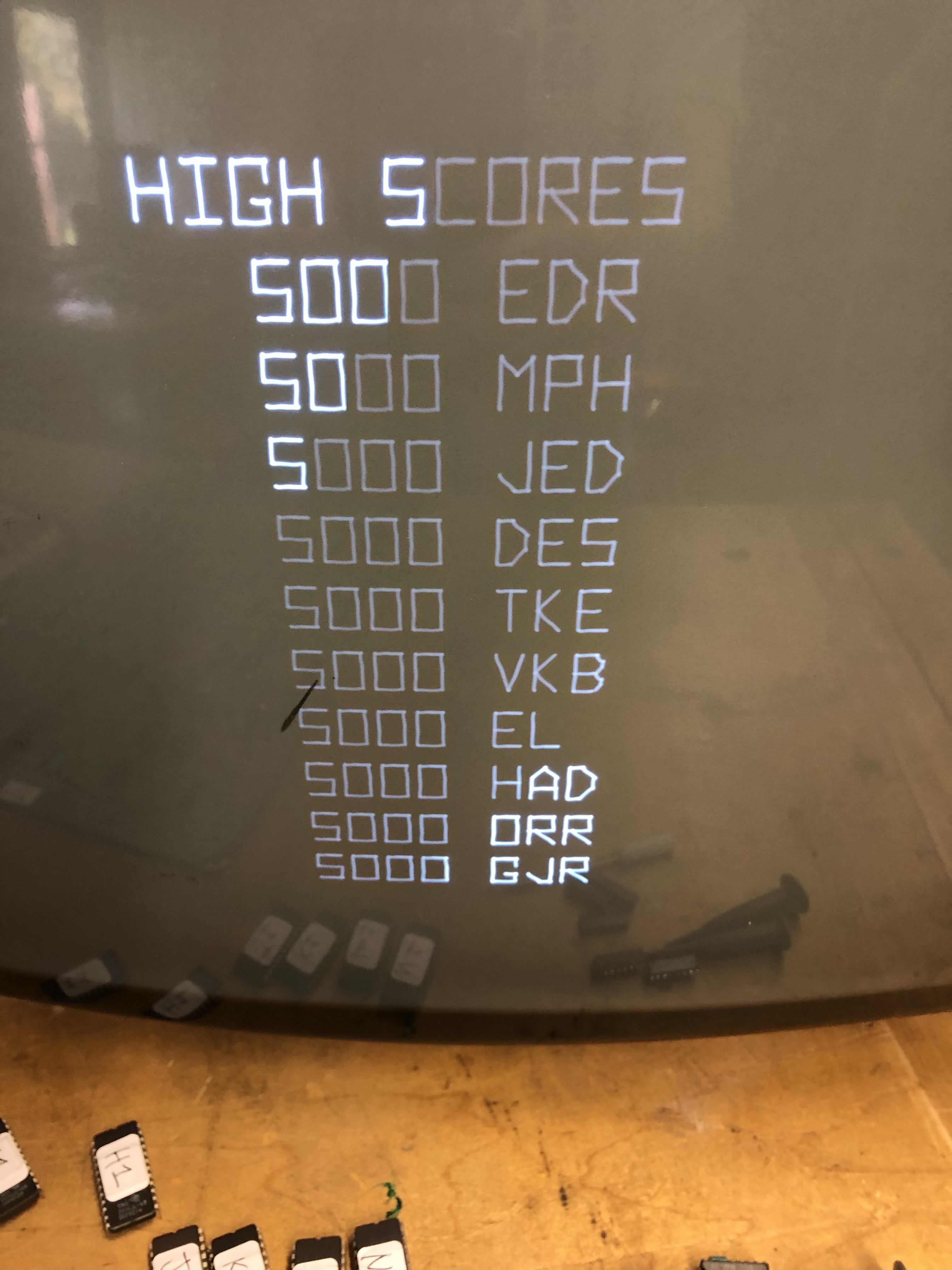
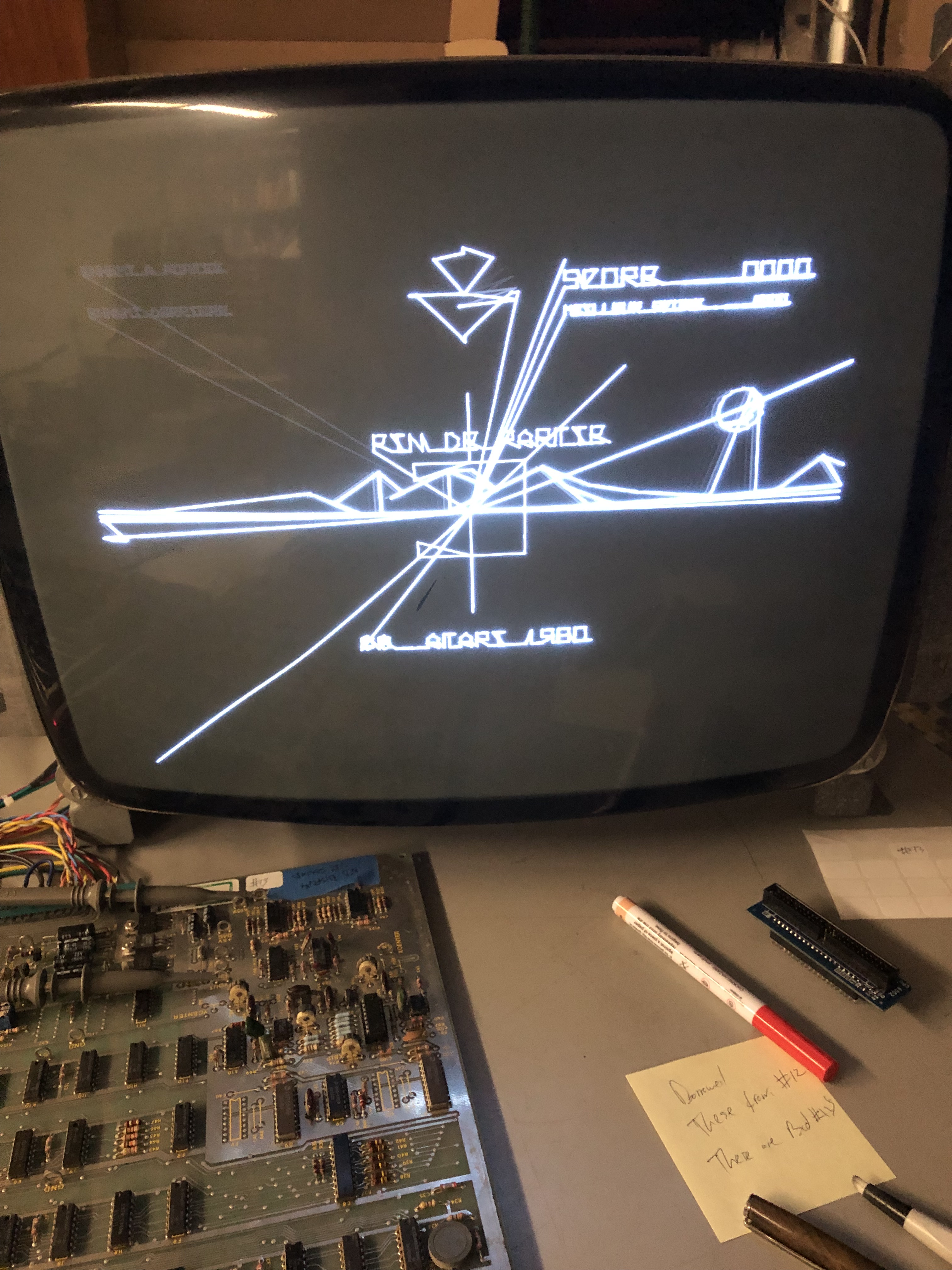
The vectors all have a wiggle in them. It appears to be at the end of the vector lines based on how they are drawn. They are all very consistent too.. On the high score table, all of the wiggly 0’s are identical. It’s most visible on the D’s.
My Asteroids Deluxe cocktail and uses the same monitor.. No difference – it’s not the monitor.
I’ve gone through all the IC’s in the analog section at this point and started swapping out capacitors. I’ve worked on this for a while and have not been able to isolate this issue. It appears to be analog in nature. One unique item (I think) is that the distortion is at one end of the vector. Even vectors that change length such as the rolling letters or the geometric shapes that move in out, the length of the distortion stays the same even though the vector gets shorter. I figured I messed something up during ‘the incident’.. I’ve checked lots of things, replaced all of the .1 and .01uf caps that surrounded the -15v chips (and some others).. No joy.
Along the way – the 7815 voltage regulator died.. It was an interesting failure to watch in the analog section. The game would run for a minute, then the screen would stutter in both the X and Y directions until it collapsed in a mess of vectors and went blank. While there, I replaced the 7805 regulator for completeness. Leading up to this – the screen had been changing size now and then.. I knew something was going on.. glad it finally failed.
For me – the best way to figure out what is wrong with a board – is to have another.
Board #2 – Now I’m mad.. This board isn’t going to win.
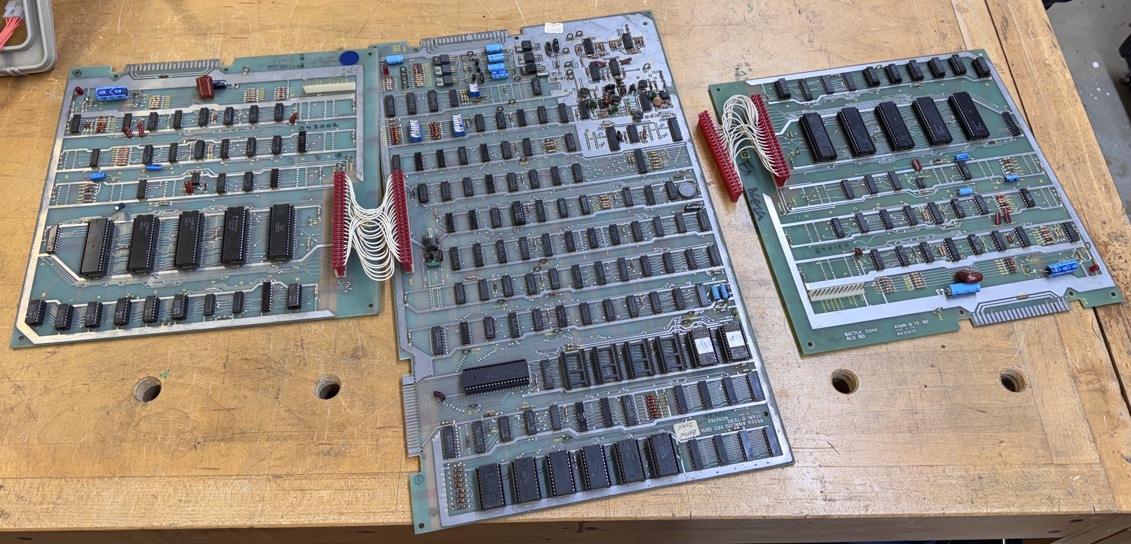
I picked up a second set of Battlezone boards so I had a better reference point.
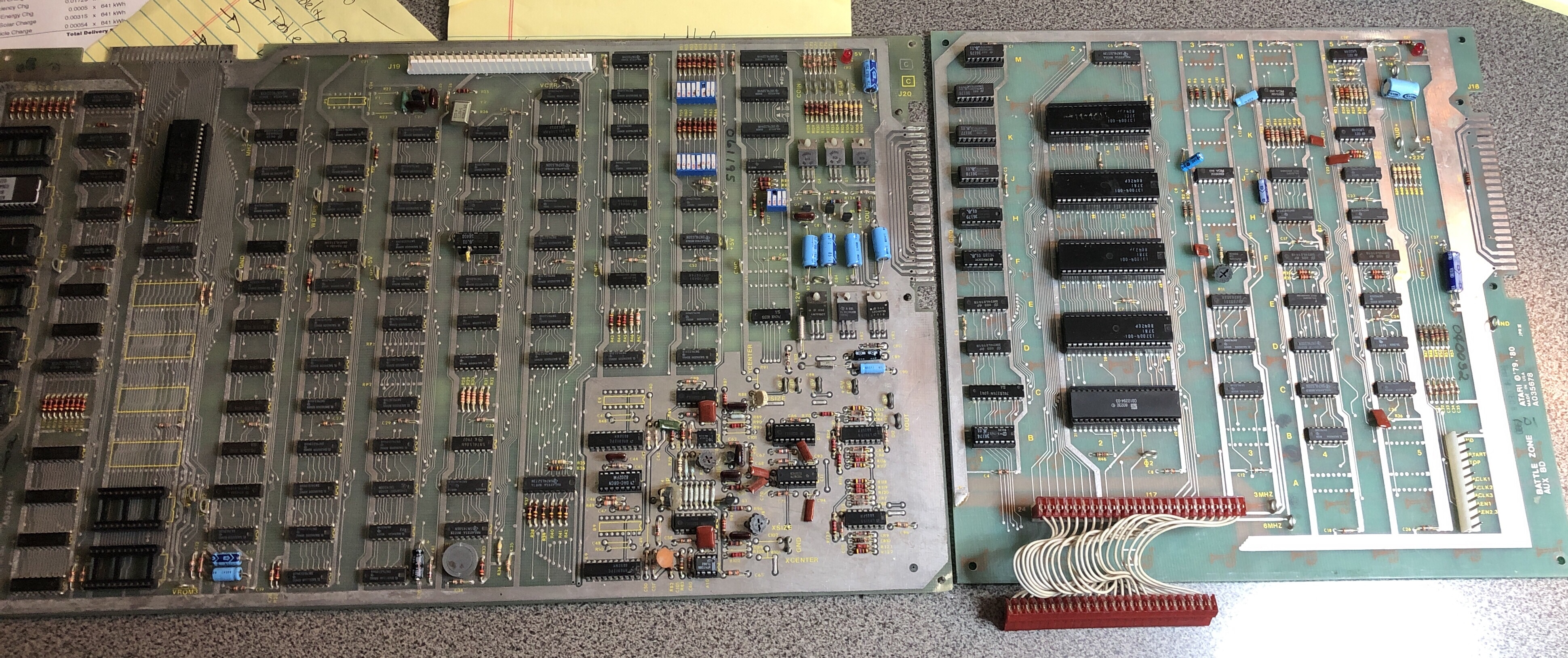
Board was sold as not working, missing chips. I put it through my standard checklist. Remove, test, clean, inspect, etc.. The AUX board was complete. Checked all of the PROM’s and they were good. Swapped it into the test bench with Board 1 and it worked fine! That’s a plus. I never expected it to fix the vector issue since both generated and static vectors are distorted. I determined that there are sound issues with this AUX board, explosions of tanks are missing, so I have a little work left. Haven’t swapped the Pokey yet..
The main board was a different story:
- Missing 4 EPROMS
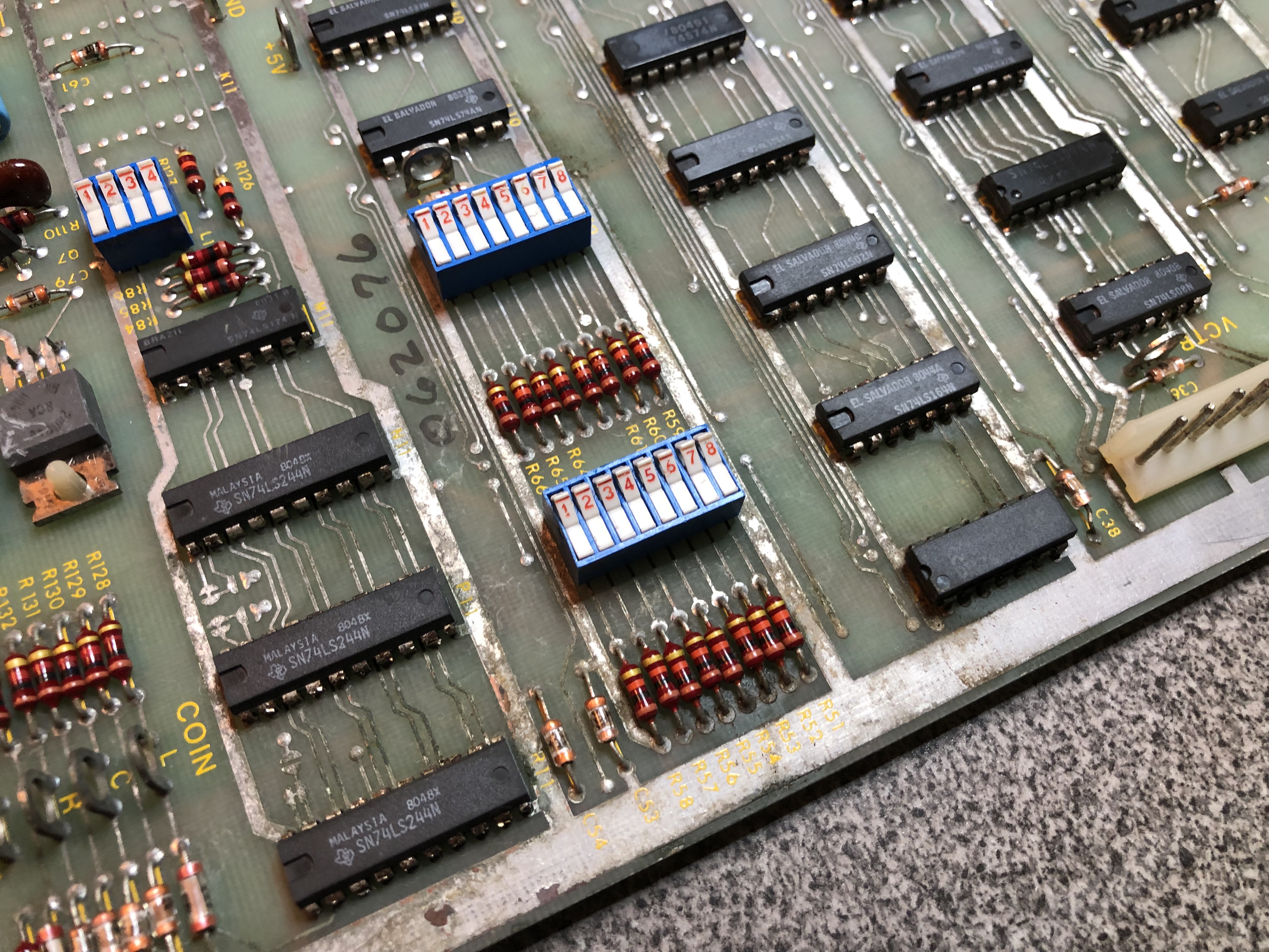
- 2 of the 3 dip switch blocks were busted
- 2 of the pots were busted
- Socket at K7 was mangled and the PROM had a broken hack leg to match the mangled socket.
- Socket at D1 was mangled
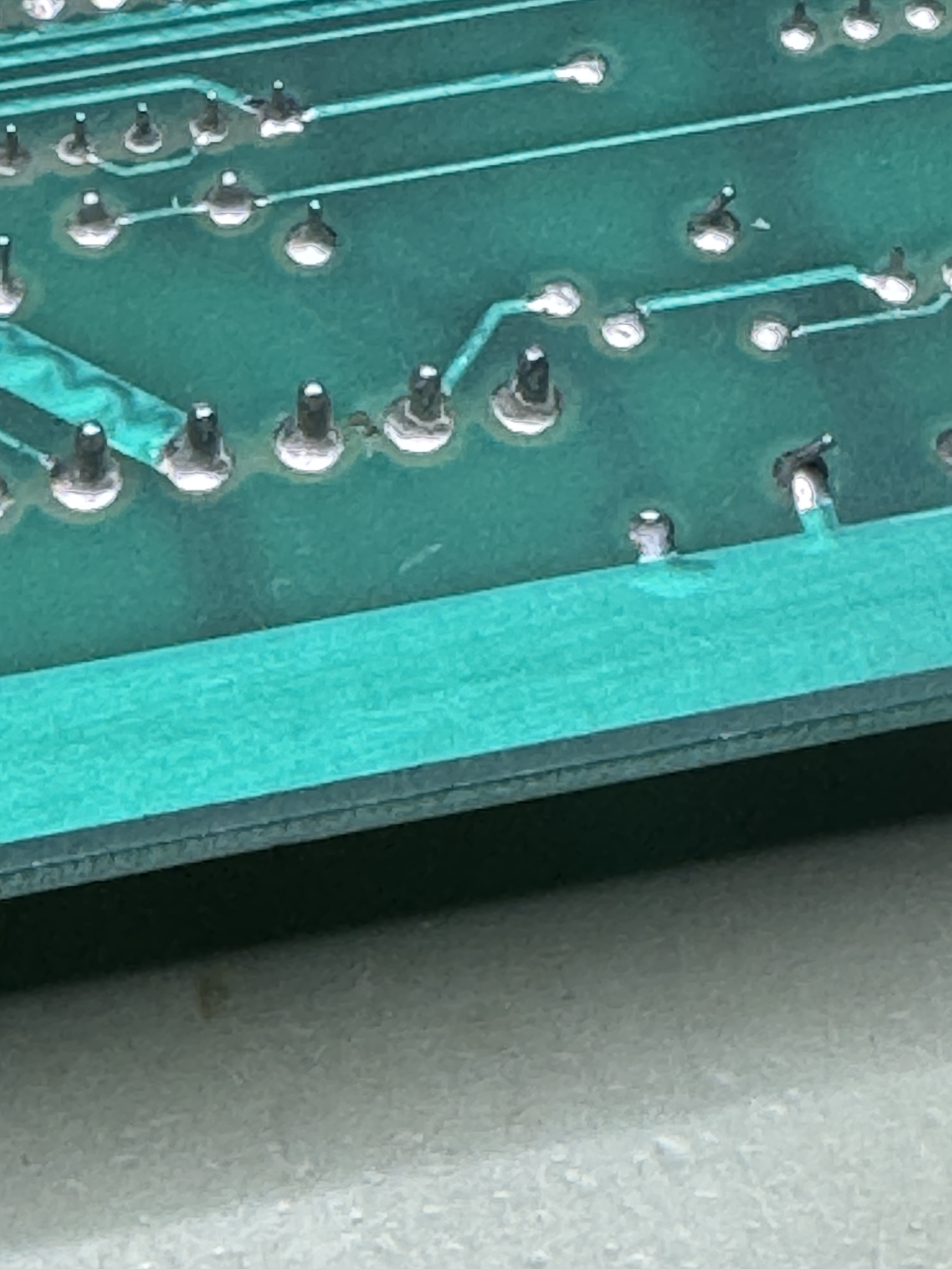
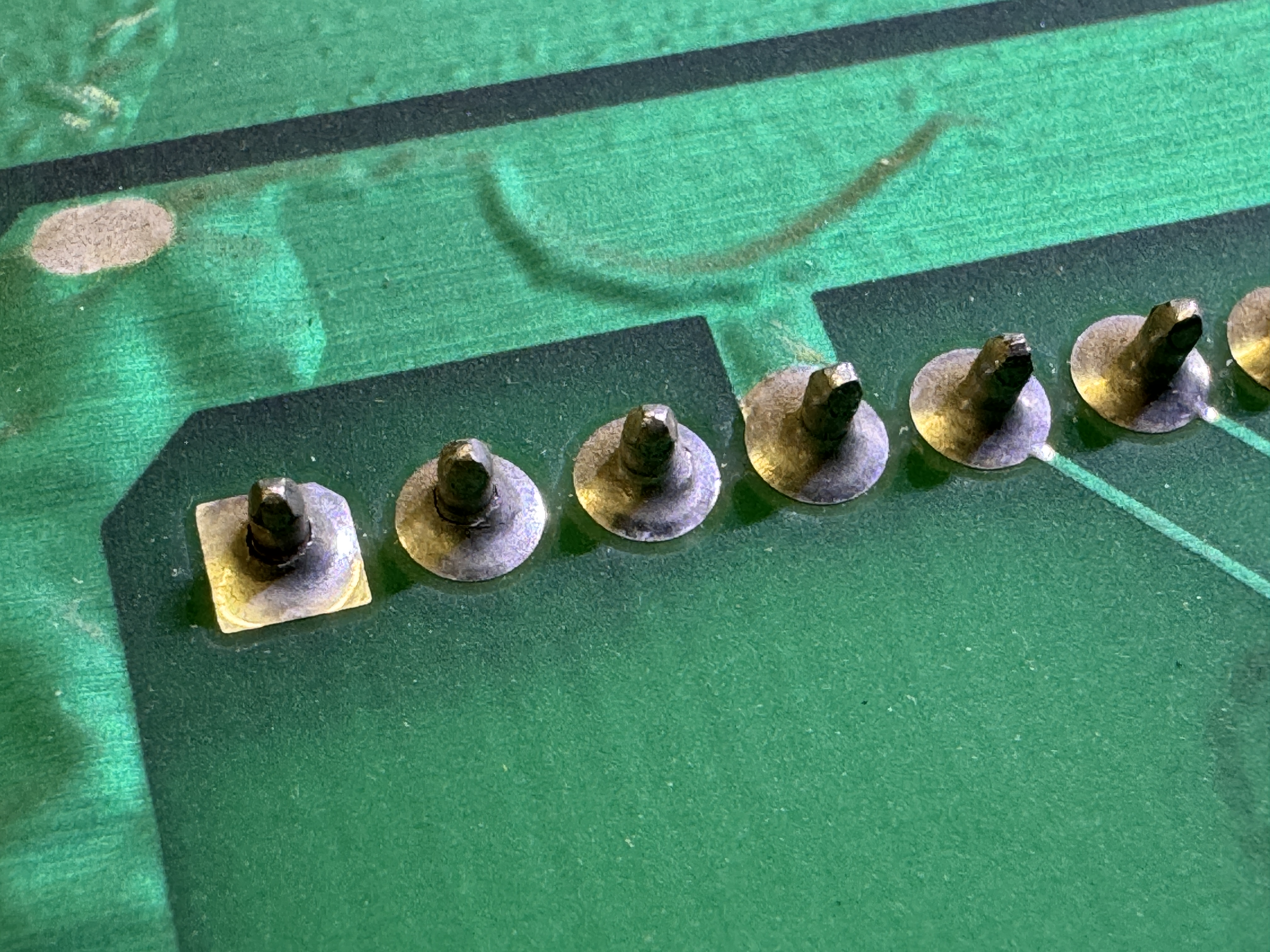
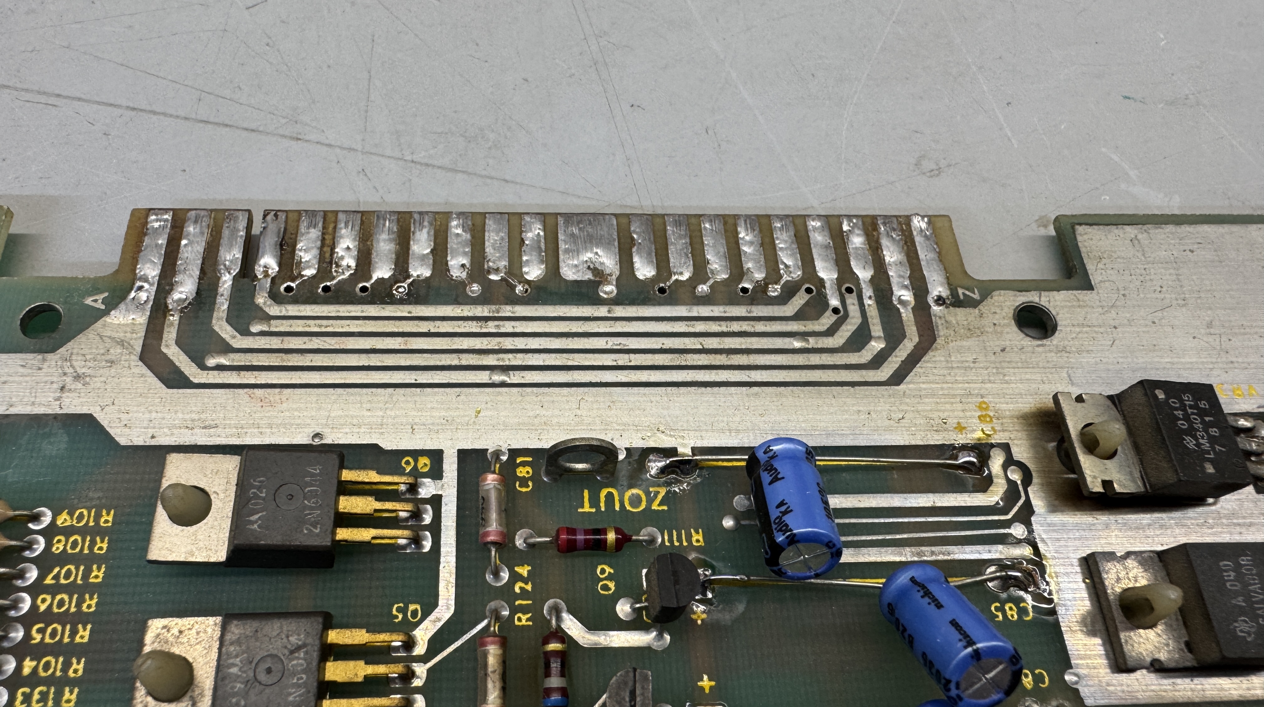
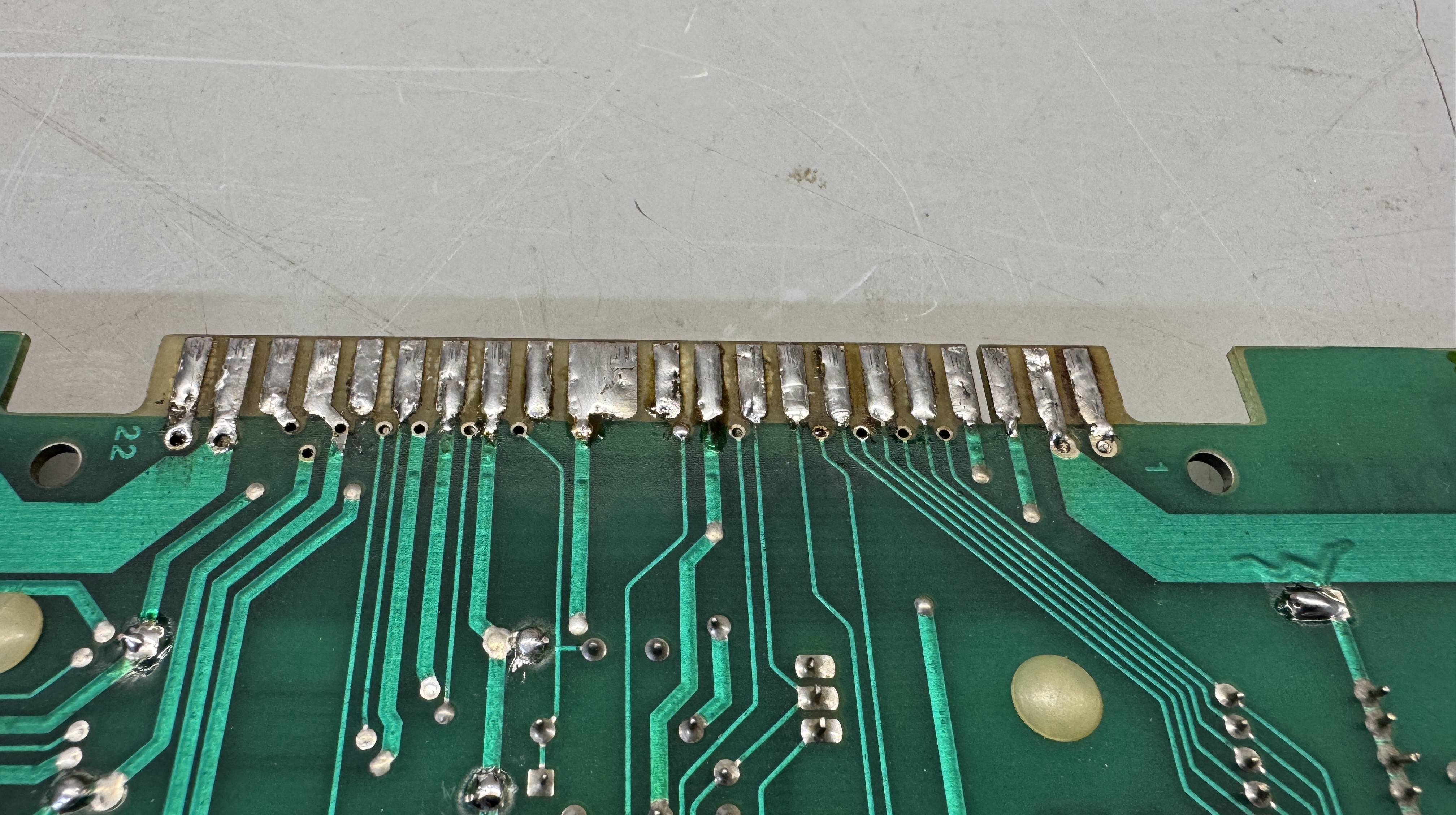
- The fingers on the PCB card edge had all been flowed with solder to ‘thicken’ them it seems. I’m guessing it came from a cabinet that had a loose edge connector. I removed the solder and the fingers below were perfect.
- One bad 2114 RAM
After working though all of the repairs.

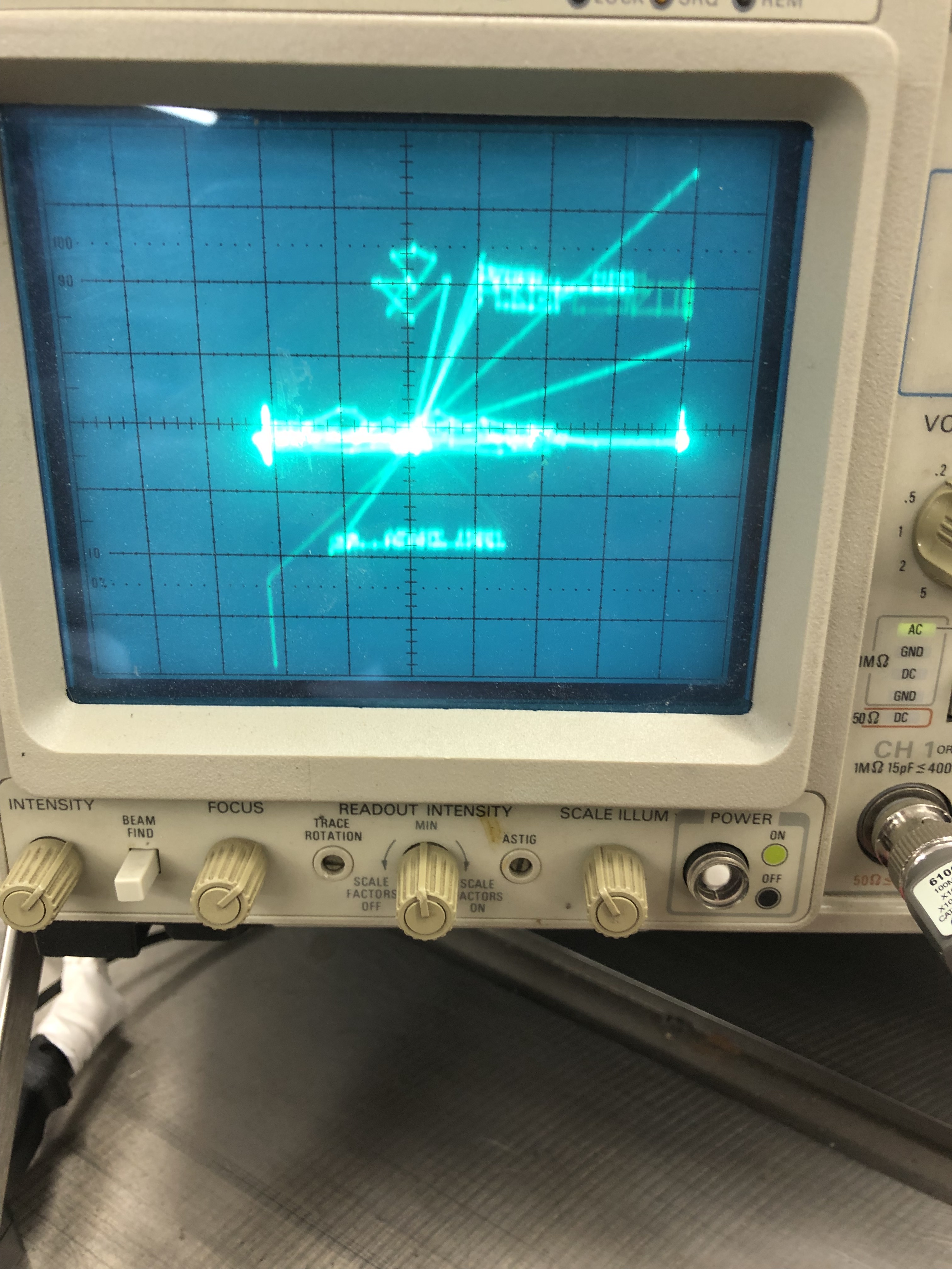
It fired up on the scope the first time! Fantastic!
Connected it to the CRT:
Identical.. It’s identical.. I’ve been chasing what I thought was an analog section issue for a while … it looks it .. right? Completely different board set.. Same exact issue..
Here are all the things I cross checked that present the identical issue:
- Checked against two CRT’s (Bench and Asteroids Deluxe) again.. – same
- Checked both board sets – 2 Main boards and Aux boards – same
- Swapped out the Battlezone ARII with my Centipede’s ARII – same
- Swapped in power brick from Centipede (what else is there?) – same
- I had burned ROMS for both boards – maybe a ROM issue?
- Board 1 had a Braze kit.. Popped it in and pulled the burned ROMs – same
- On the minute chance the power brick from a vector game is different than the raster games, I swapped in the power brick from my Asteroids Deluxe to be 1000% sure something funny wasn’t happening. – same
- Checked all board voltages.. – good
What’s left? The wiring harness that I built? It’s pretty minimalist. However – I even swapped the X,Y,Z wiring going to the CRT.. No difference.
I verified power to the monitor – 60VAC.
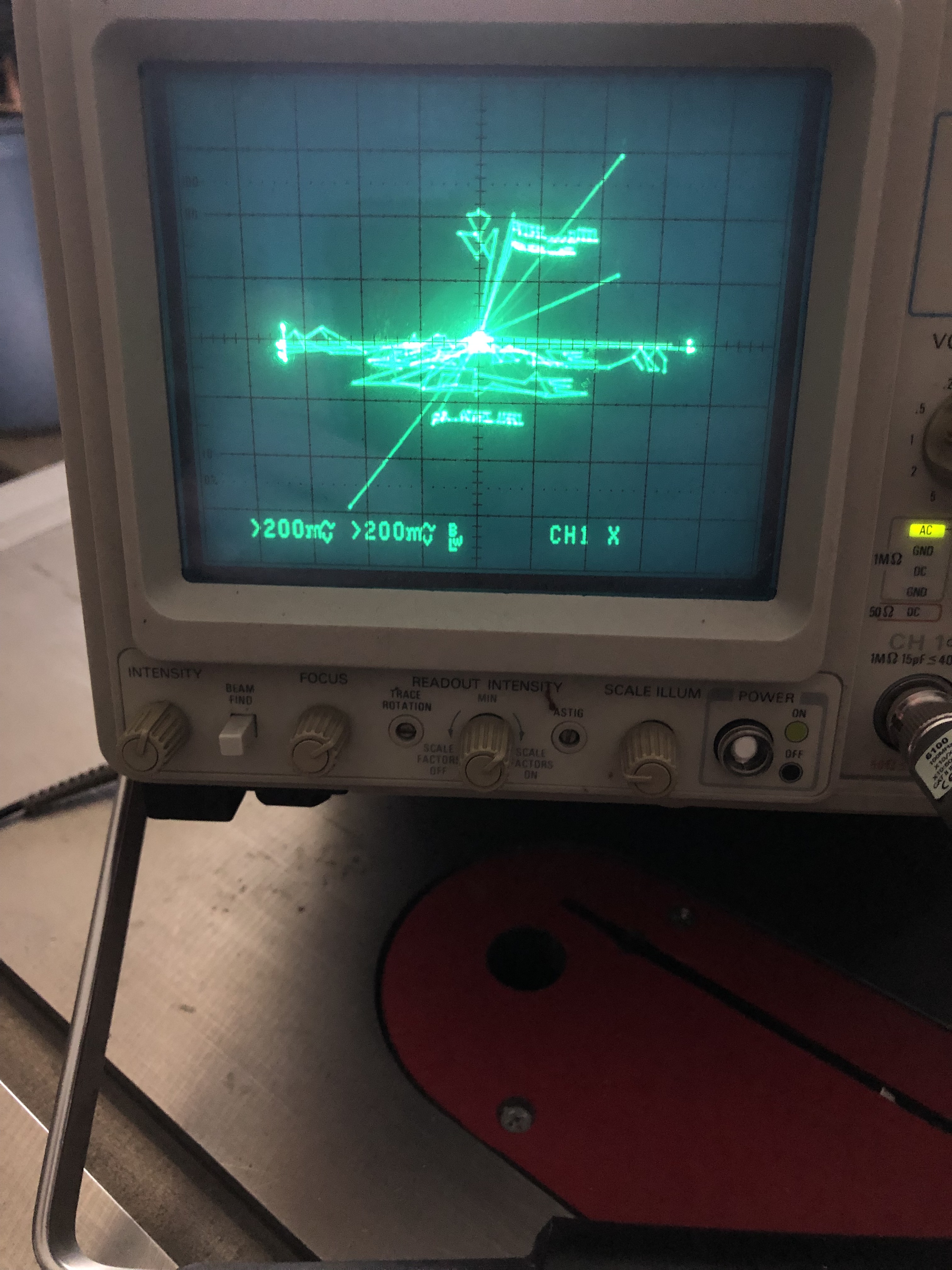
As luck would have it – I just acquired a Tektronix 2465CTS analog scope. I’ve been hunting for one for a while locally.
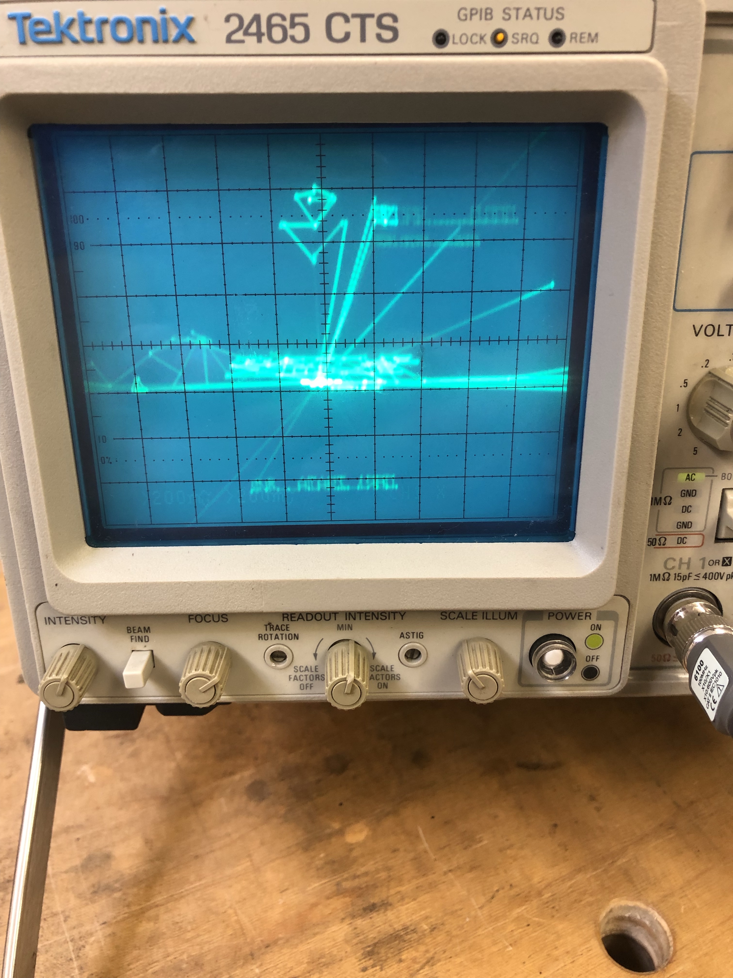
Hooking it to the scope directly bypasses all of the power supply/wiring for the monitor, etc. When I look real close. – same
In Summary – I can’t seem to find a cause for the little wiggle in the vectors. The only common component left between everything I’ve swapped is the harness I made – which I’ve checked numerous times.
Maybe some ground that I’m overlooking? There are grounds, etc. that run through the coin door.. But I’ve ground clipped everything together to be sure. – same.
Finally – anyone within a few hours of Boston with a Battlezone? The boards are safe – A real cabinet is the only test I have left.
I can’t imaging 2 board sets with the identical issue:
– Board1 with a bunch of analog stuff replaced.
– Board2 where I didn’t touch anything in the analog section.
UPDATE:
I was able to test the boards in an real Battlezone cab. No vector ‘wiggle’. My only guess is it is something in my bench harness. Problem solved.
Aux Board Update:
The Aux board worked, but the sounds were messed up. Once I got back to it – I found that C29 had been ‘borrowed’ from this board at some point in its life. A .47uf Mylar cap. Once I replaced that – all the sounds worked properly again. A few other caps had been replaced with radials at some point. I swapped them out and put axial caps back as they were originally. The radials worked, but looked terrible.
Board #3 – Picked up a set for more BZ repair practice
Set was sold not working and missing a ROM. Otherwise it is in pretty nice shape

Not 100% sure this board has ever been worked on.. It was missing a ROM.


My standard checklist applies. Remove all socketed chips, wash boards, clean legs, etc..
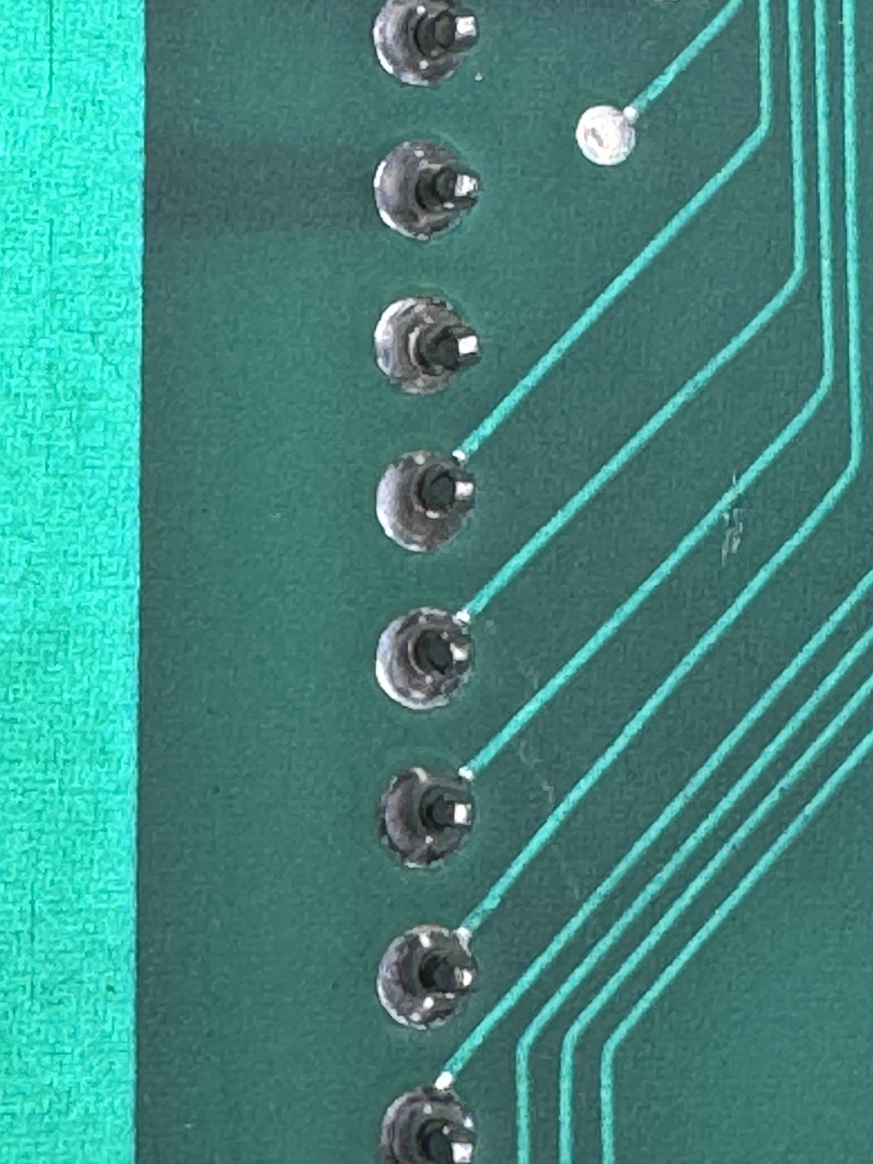
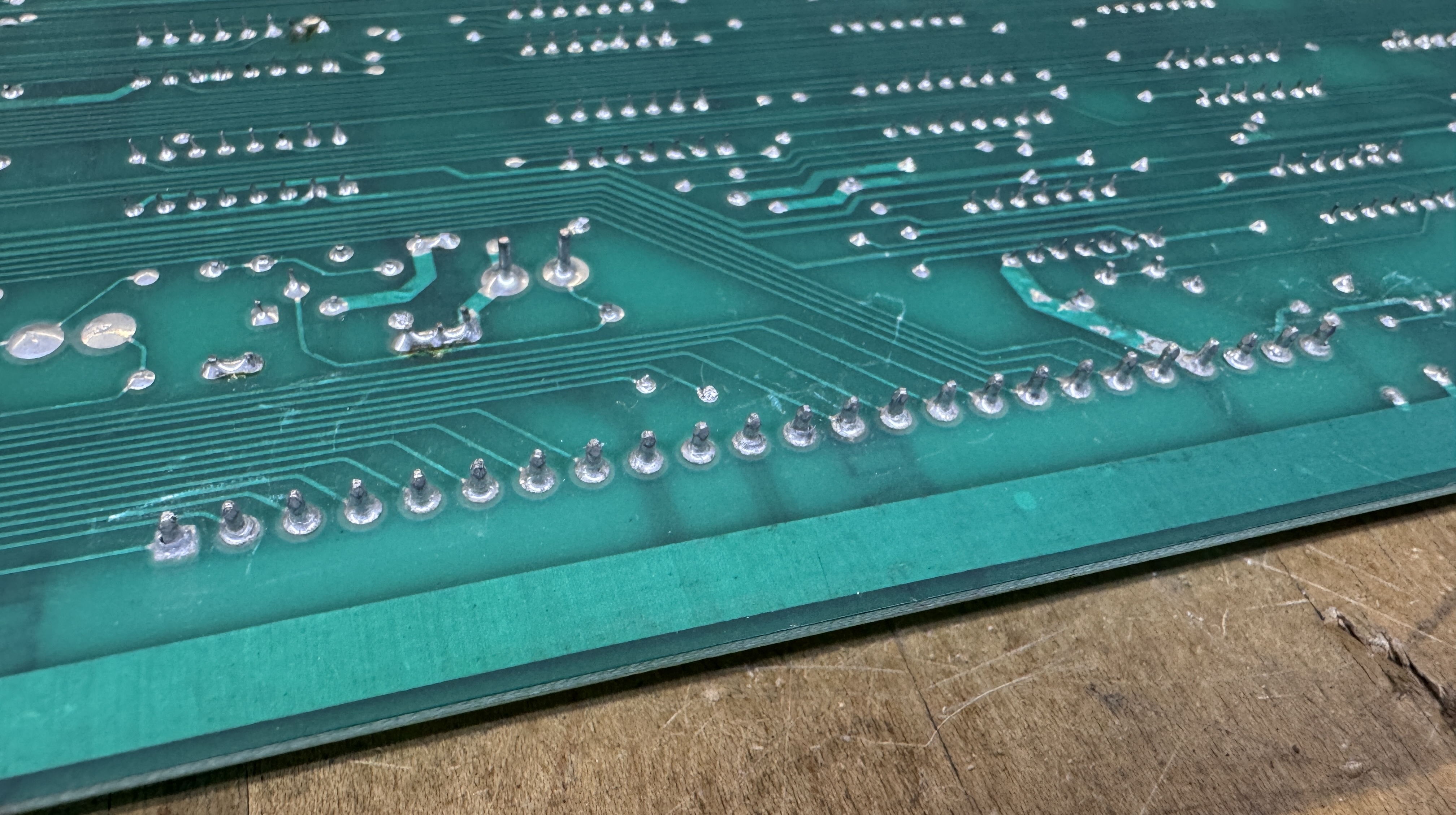
Only issues were one missing ROM and 4 additional ROMs that checked bad. Surprisingly theses are mask ROMs. I’m not sure I’ve ever run into one bad one, never mind 4. I did reflow the board interconnect pins.. Nice view of the before here.
Once I got the harness out and everything connected. No beeps, no resetting or watchdogging.. The board was running? I put it on the analog scope, turned some knobs and got the test screen. If I put it in game mode – you could here it rumble for a second or two.. then the game crashed.
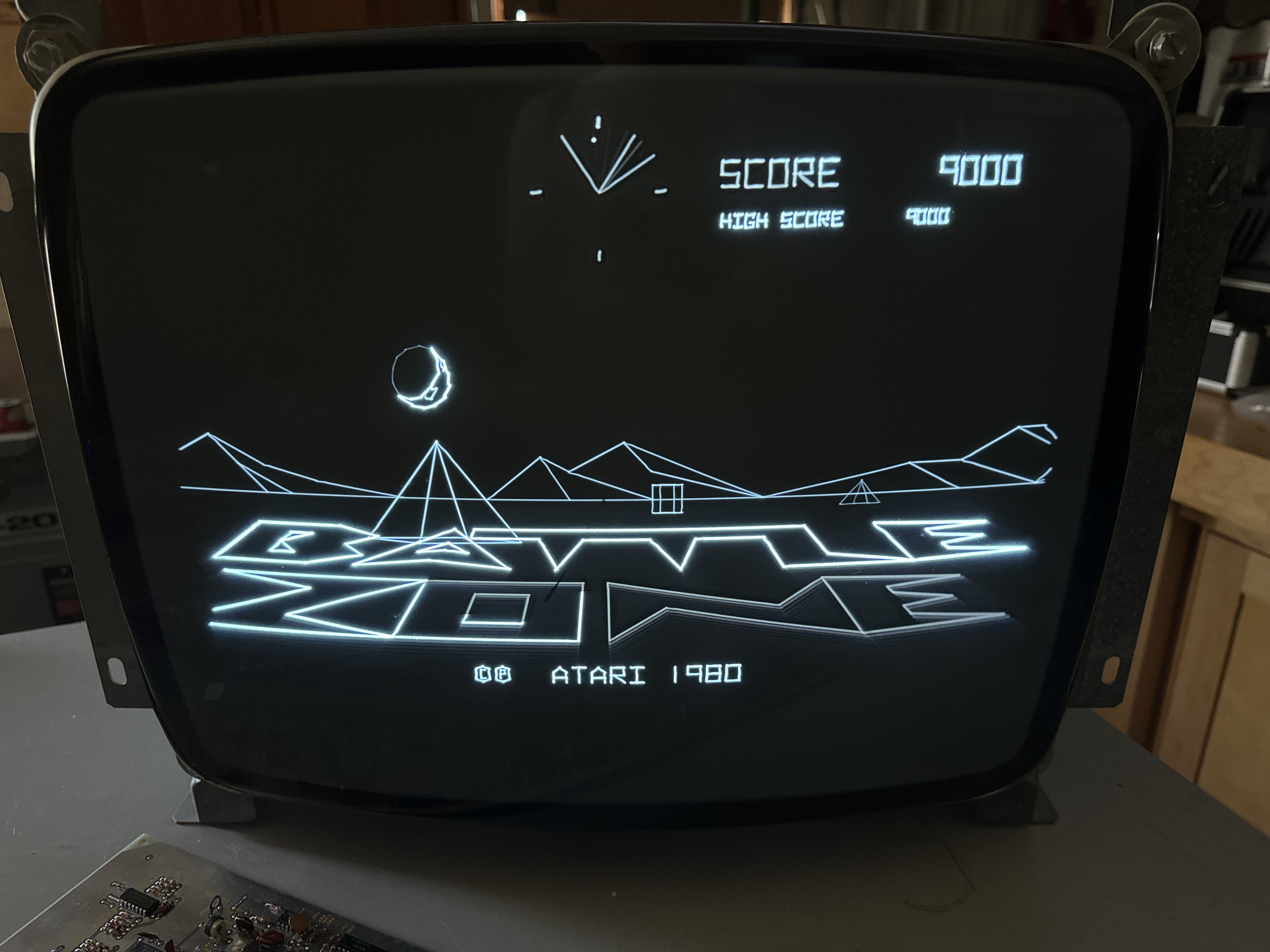
Ok… if I got the test screen on the scope – let’s see it on a tube….
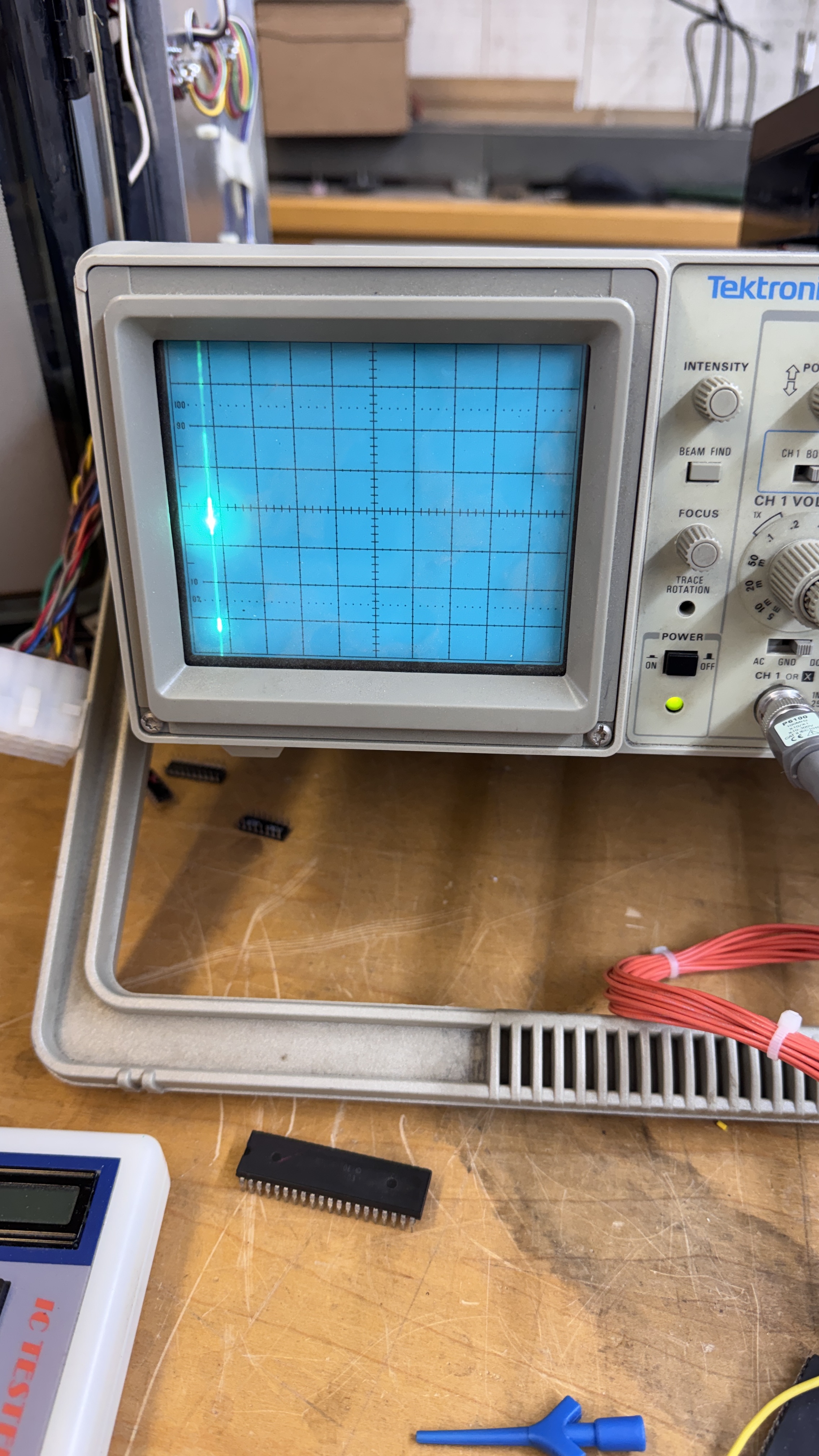
I tried a couple times and got the spot killer. But once I tried I saw this.. Everything there, just small!
I was only getting ~1.4v from the X and Y outputs.. I thought maybe it was the TL082’s? But both of them? Didn’t seem likely. Removed and socketed them and retested on the scope.. No change. Then I remembered DIAGSTEP (tap/ground R129 while in service mode) and step through the sequence. It ends with an explosion sound – A nice little feature. It avoids a fair amount of the vector circuits I believe. It drew the lines nice and tiny just like this..
At this point I made the decision there were no issues in the analog section – it was doing as it was told. Since the game would crash, it was outside the analog area.
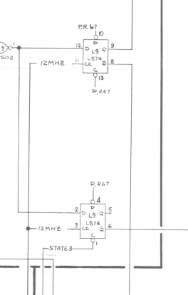
Paging through the schematics..
I immediately looked here and thought.. If the very first counter was bad, it would be the most significant part of the count drawing the vectors to length. I scoped it and it had the clock going in 12 MHz and a 6 MHz count coming from every output.. Interesting failure. The next counter in line @L6 was starting 4 clock divisions higher than it should have. Resulting in tiny vectors!
Replaced the LS161@K6

Board works!
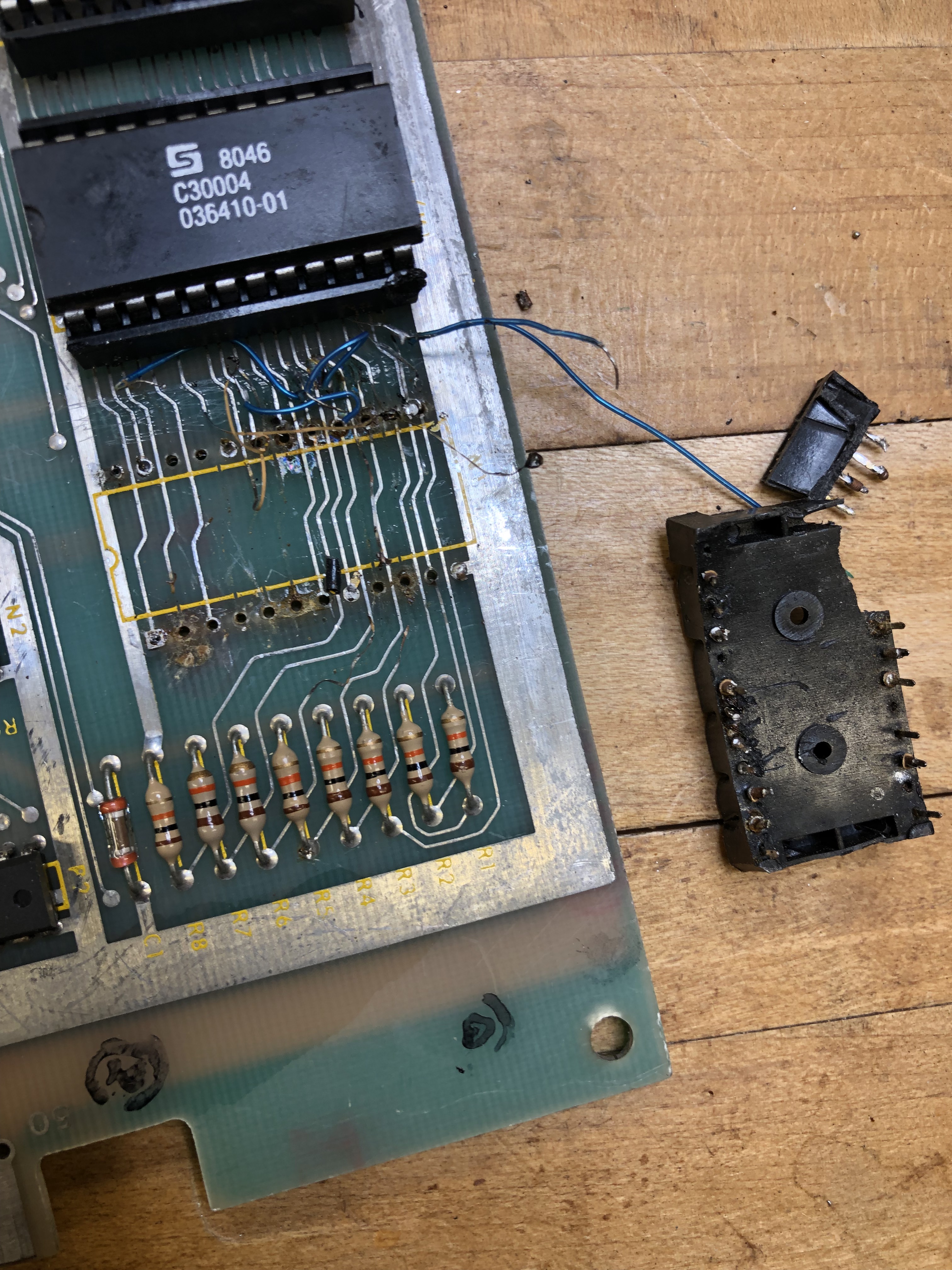
Board #4 – Picked up a lot of 3 BZ main boards – this was the nicest looking of the 3.

- ROM 036411 @K1 was missing
- C56 Broken in the Analog section
- No -15V
- Had an AUX board with Pokey in backwards
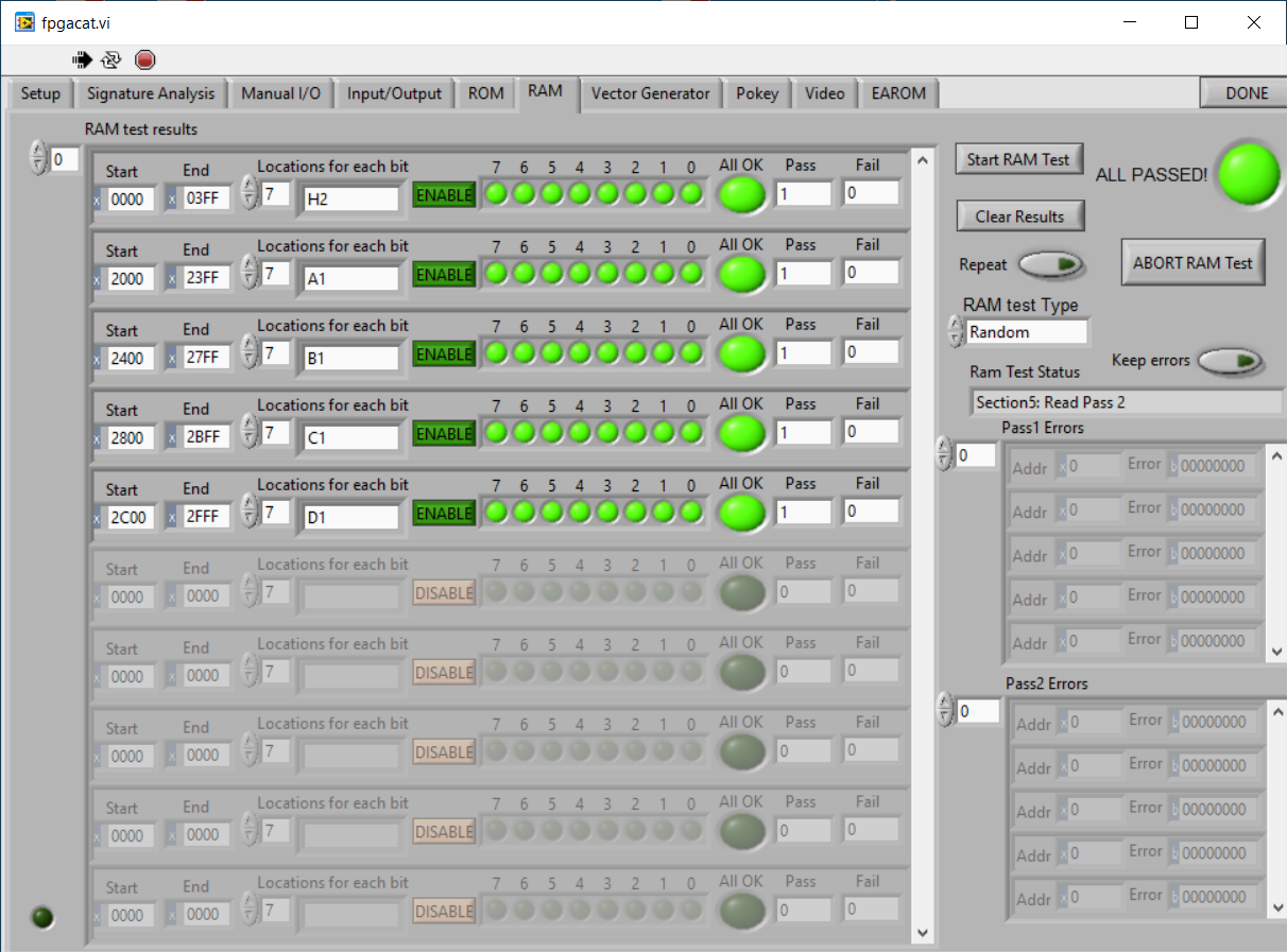
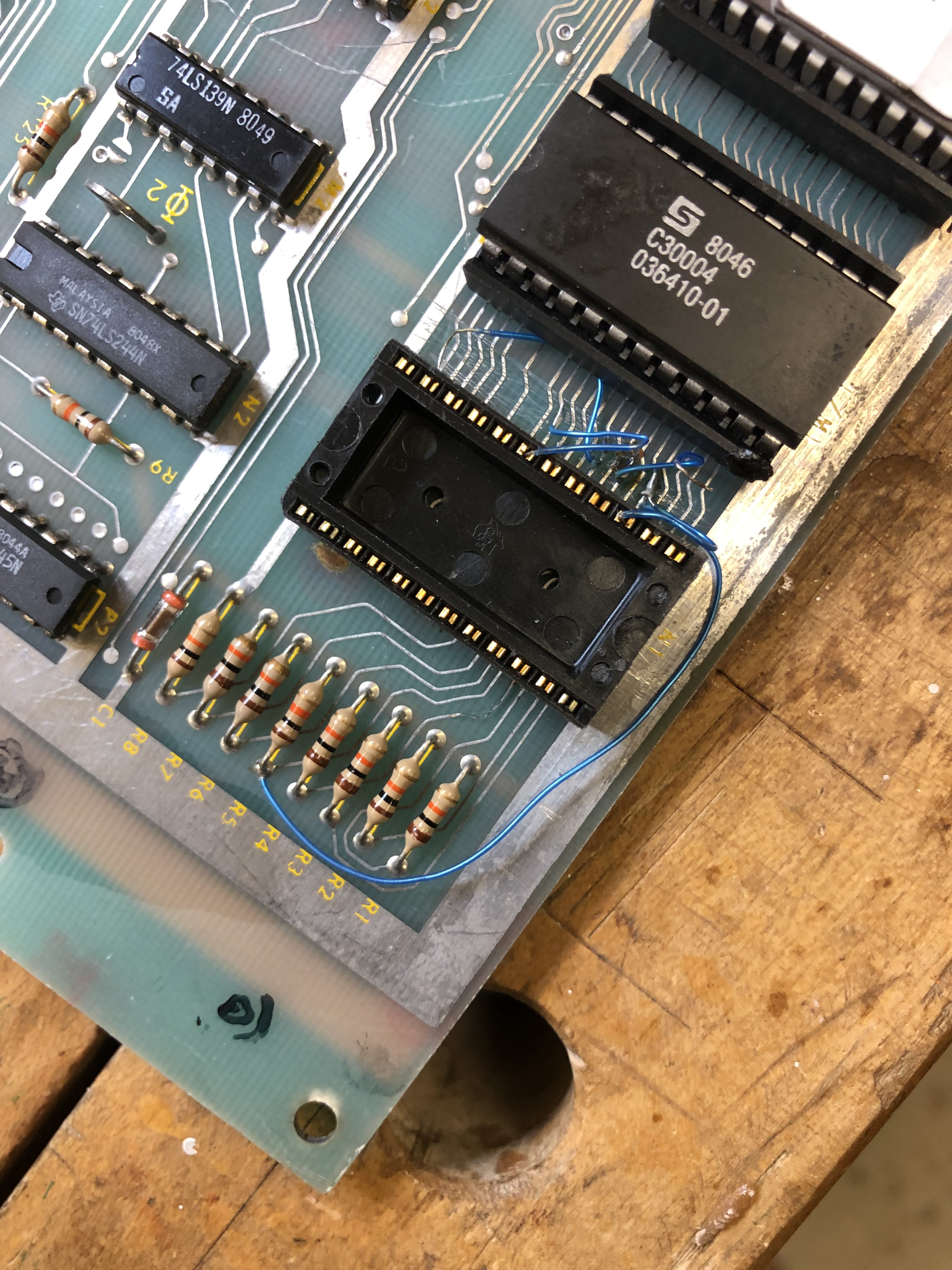
After initial cleaning, etc.. Plugged in the FPGA Catbox to check ROM and RAM in circuit. Note – all of the ROM checked on my reader. The ROM kept flagging bad and depending on if a ROM was plugged in to E1, the issue would move.

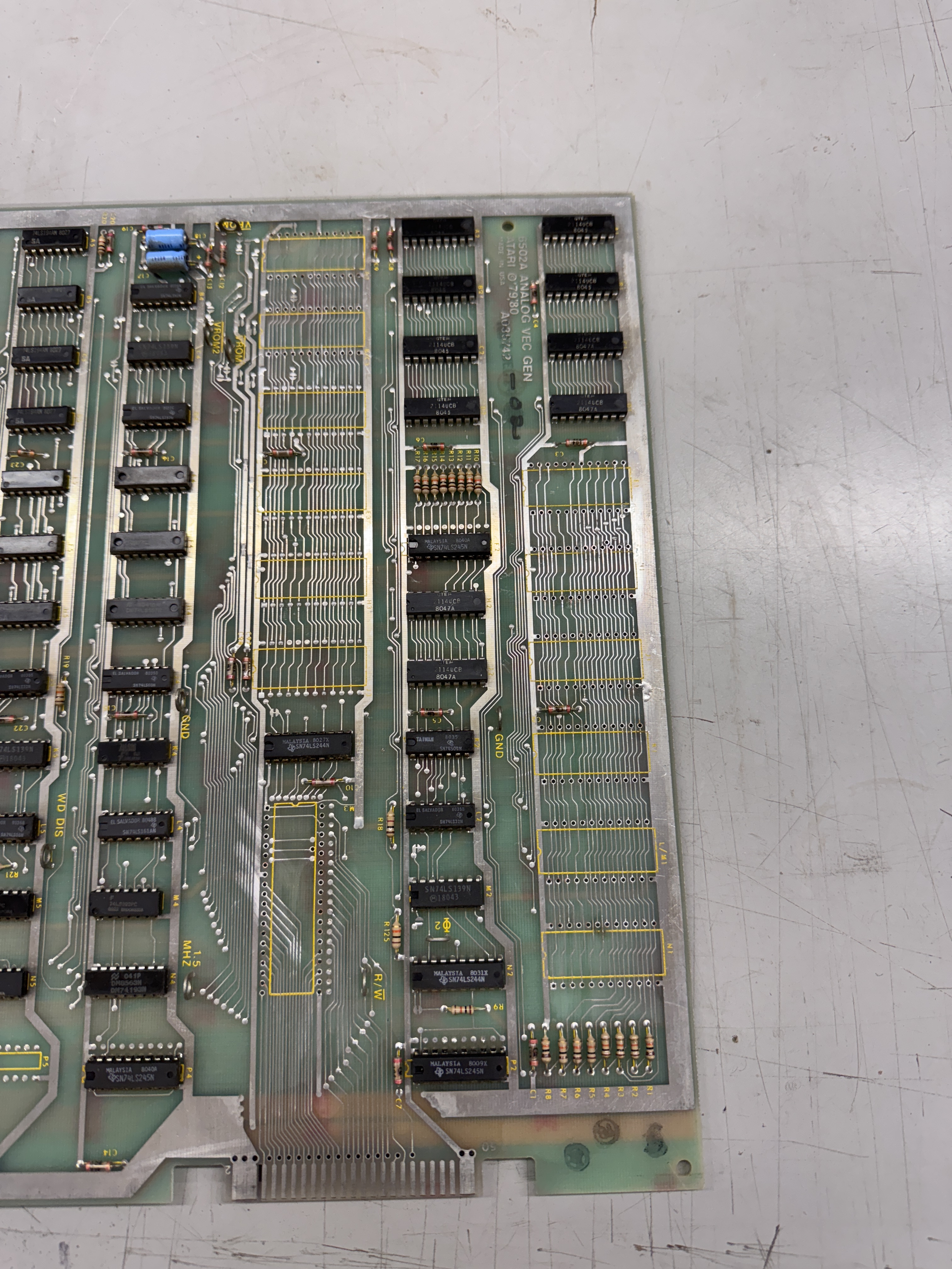
Because I could plug a ROM in/out while testing and watch the results change, it pointed me toward a decoding issue. Eventually I found a tiny solder splash from prior work that was shorting a leg on LS139@M2 pin13 to the trace that runs between it and the next leg.
I would have found this the old way – but testing in circuit sped up the process.
Once that was done – Got the game to play blind. Progress. After replacing the LM7915 to restore -15V.

Here is what Battlezone looks like when C56 in the analog section is broken. Once I replaced that the vectors all straightened out – but I lost some of the screen. Replacing the DAC @A9 got me Battlezone on the scope.

On a monitor – not so much. The Z circuit was not working. This board had been worked on in the past and nearly all the chips in the analog section had been socketed. Replacing the TL084@C11 and the LM319@B12 restored the Z-outputs.
Board works!
Update: During burn-in testing.. about 20 hours of running the game started crashing. One of the bitslicer/transistor arrays on the AUX board went bad. Replaced. Board works again.
Board #5 – Received a board for repair – told it was not running..
Coin counter clicking, Nothing in test mode.. etc.
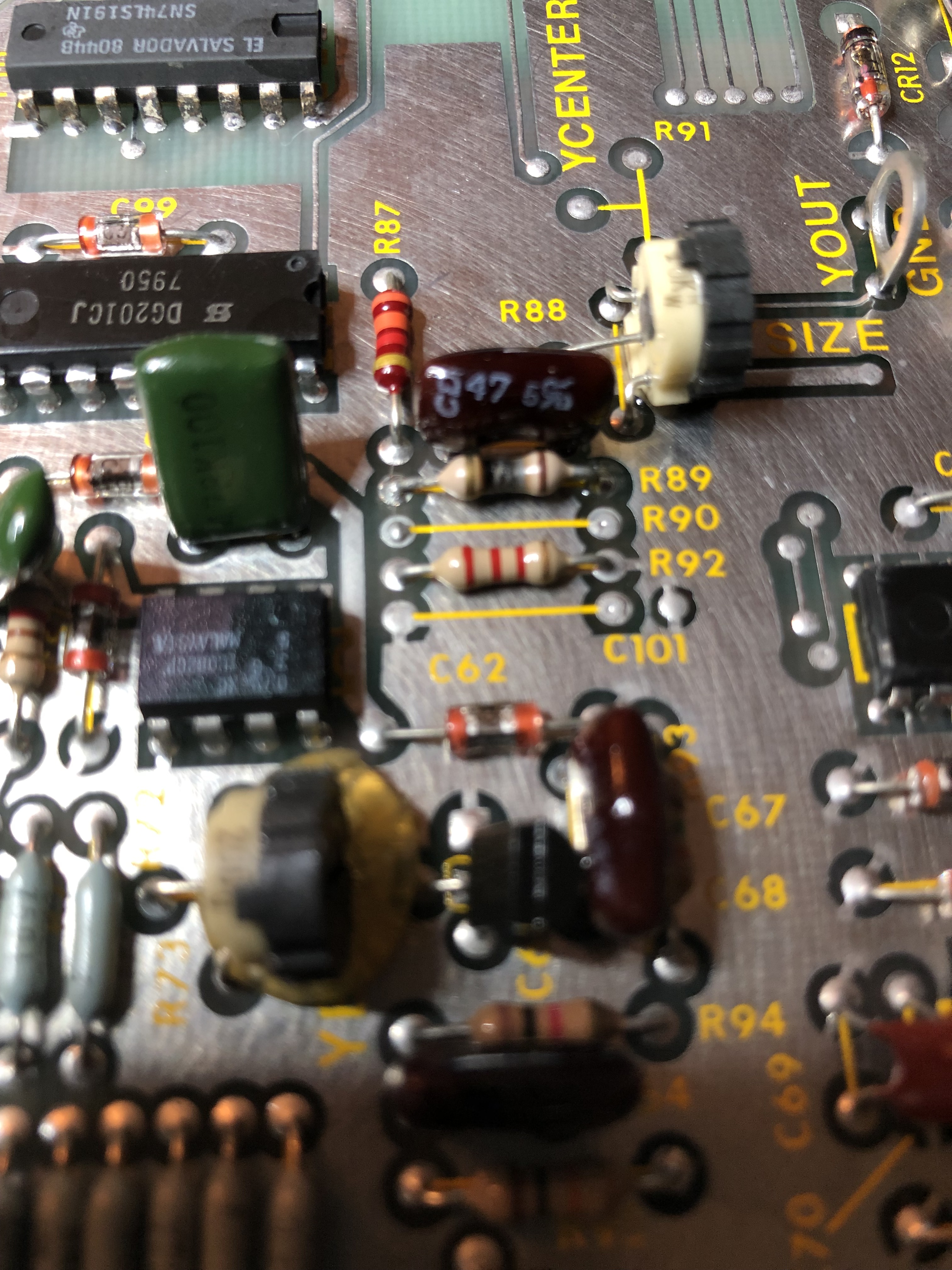
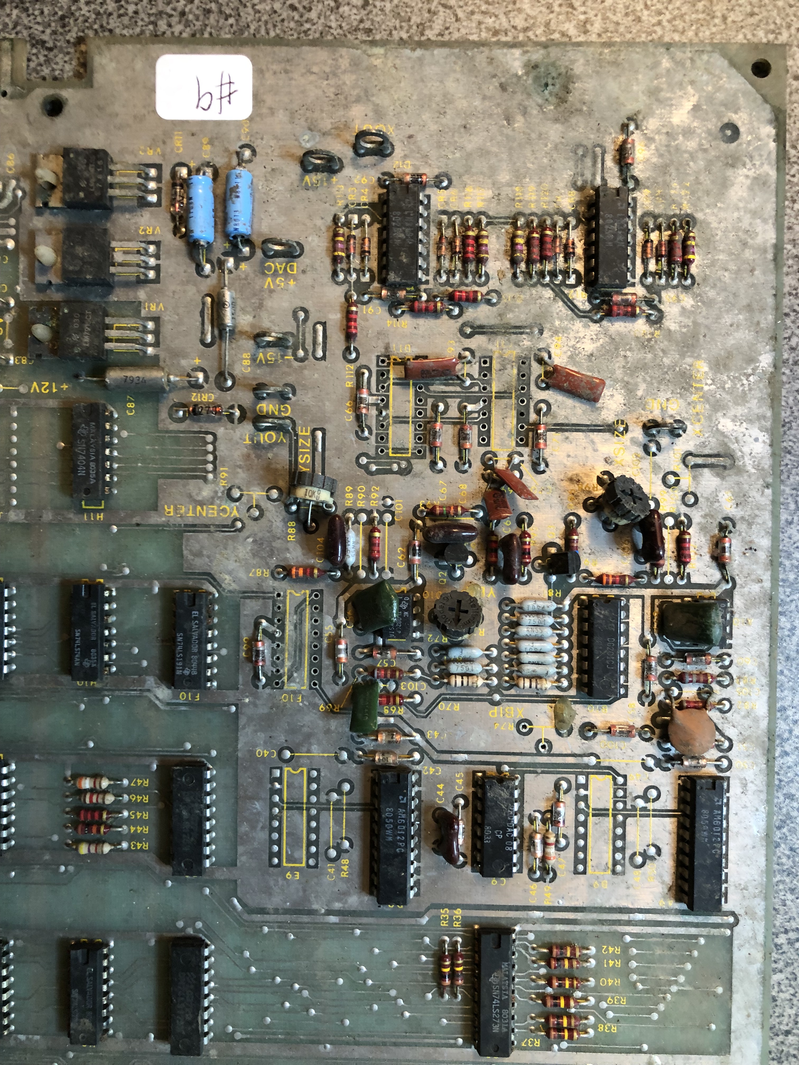
Did routine maintenance, but nothing wrong with it that I can tell – boards running. Except I could not get the X or Y size to adjust large enough. Found R89 here burned and incorrect value. R99 had also been replaced with the incorrect value. Corrected and the screen can now be adjusted.
Will re-check with owner on power and wiring harness potential issues.
Board works!
Board #6 – Received a board for repair
Owner said the board was out for repair for a year – then returned unfixable. He said that it showed a few signs of life when powered on. Couple of beeps and a random vector or two.
Main board after initial cleanup:
- Bad 6502
- Showed bad ram @C2, C1
- Some prior work
Replaced 6502 and RAM. Game booted and played blind. No Test Mode screen. Vector Generator not running.
Using FPGA Catbox: VHalt was running at normal speed, VCenter was ~2X expected timing. Working through the VG, checked all of the LS161’s – all seemed to be running fine. Ended up piggybacking the LS193’s and got the VCenter timer to correct. Replaced LS193@F5. Vectors working!
AUX Board – Working except once a game is started – Fire button is locked on.
Issue: Bad Pokey (ouch)

Replaced bad Pokey.
Board works!
UPDATE: My test cycle includes 4 days of active burn-in
Day 2 ~20 total hours of being powered on.. Vectors went bad. First thoughts were something in the analog section but I connected the Catbox first to test the AVG. All of the tests showed proper timing except the ‘VG JMP test RAM’ which had timings that were vastly out of spec. Without wasting much time – it pointed to addressing based on the test notes. My goal when I see this now is to see which chip I can mess with to get the timings to move or glitch. I piggybacked an LS194 on the data-shifters. @D5 cleared up the timing. Replaced LS194@D5
Board back in test!
Board #7 – Received a board for repair
Same owner as board #6. Board was out the same year as #6. Owner was told both the main board and AUX board had high voltage damage. Told all of the mathbox chips were blown and the set was unfixable.
Once initial inspection, cleanup, wash, chip legs cleaned, etc..
Issues:
- Crystal loose in its can (worked, replaced anyway)
- LS245@F2 was not soldered in place – was removed and just stuck back in the board
- Cap disconnected on TL082@D10
- Prior work/trace repairs
- LS244@K3 unsoldered
- Ram 2114@C1 messed up
- Bad 6502
Soldered in loose parts, replaced crystal, cleaned up RAM@C1.
All ROM checked good on the bench.
However – I could not get @A3 and @B/C3 to validate in circuit. The Catbox is very handy because it can loop on ROM checks while you are looking for the issue. Could not get the ROM to validate so I moved on to the RAM.

Checking RAM showed the 2114@A1 was definitely bad. I replaced it and it cleared up all of the RAM and ROM errors. Board booted up and played blind. So maybe not a high voltage issue after all! The RAM was corrupting the 4,5,6 data lines on the bus. Board would not go into DIAG mode.
Once booted – looking at the vector generator:

Things were not going so well for the VG.
Using the Catbox I determined VCenter and VHalt were running correctly per timings. After digging into it deeper and noticing a pattern based on the Vector program and some manual input. The timing issue only happened on long vectors with a negative X coordinate. Working through it I came up with a simple idea: Execute a long vector -1,0 This would create a 12 bit -1 coordinate of all binary 1’s. My thought was there was a ‘0’ somewhere in the middle of the 12 bits causing the vector timing to go haywire (I was correct on this)
I found that the 1’s are all passed on the DVX outputs. The LS194@B5 had dead outputs on 2 of the bits. Replaced it.
The Vector Generator lives!
AUX Board – Working except once a game is started – tank stuck turning right.
Issue: Bad Pokey (double ouch)
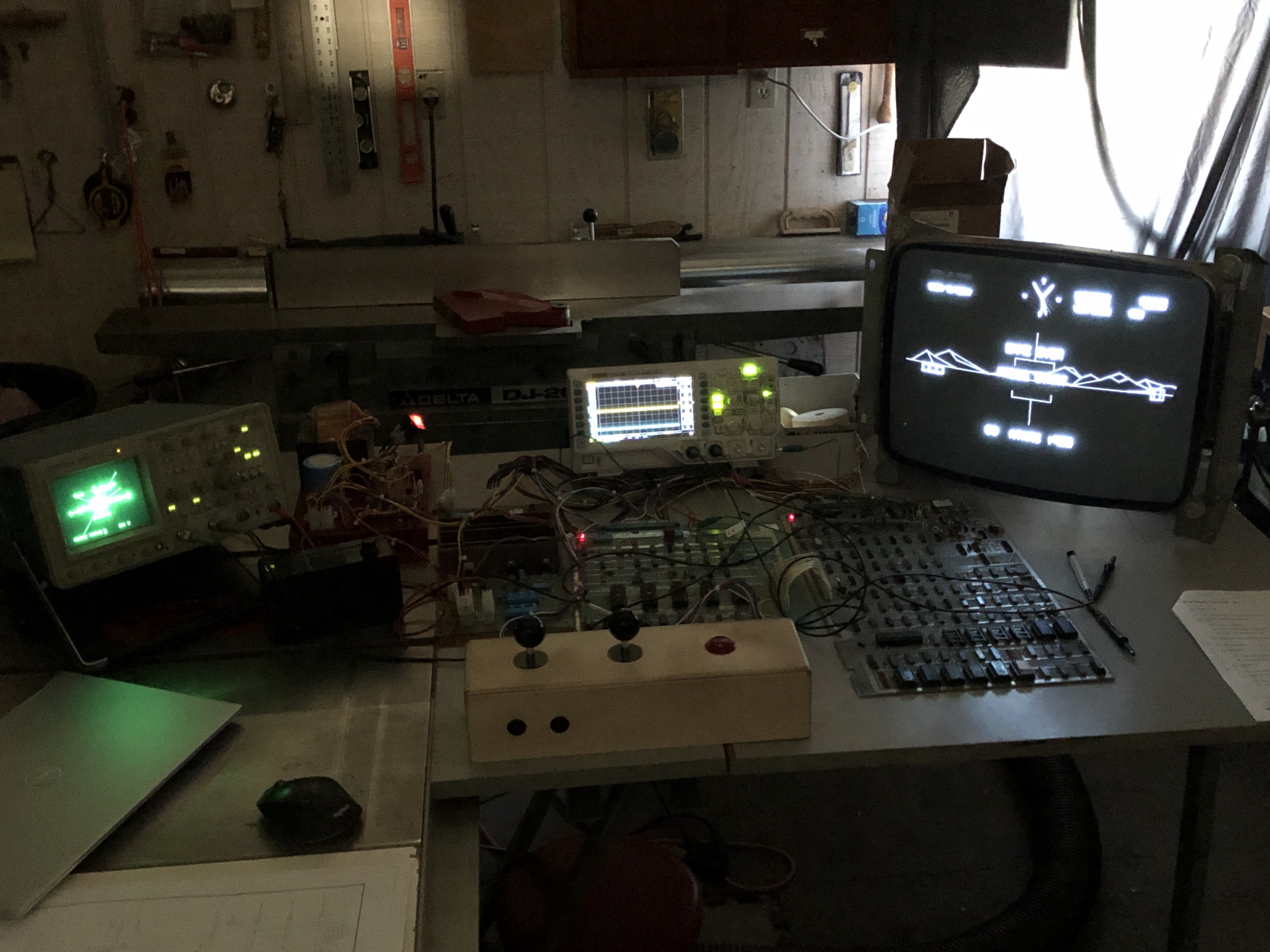
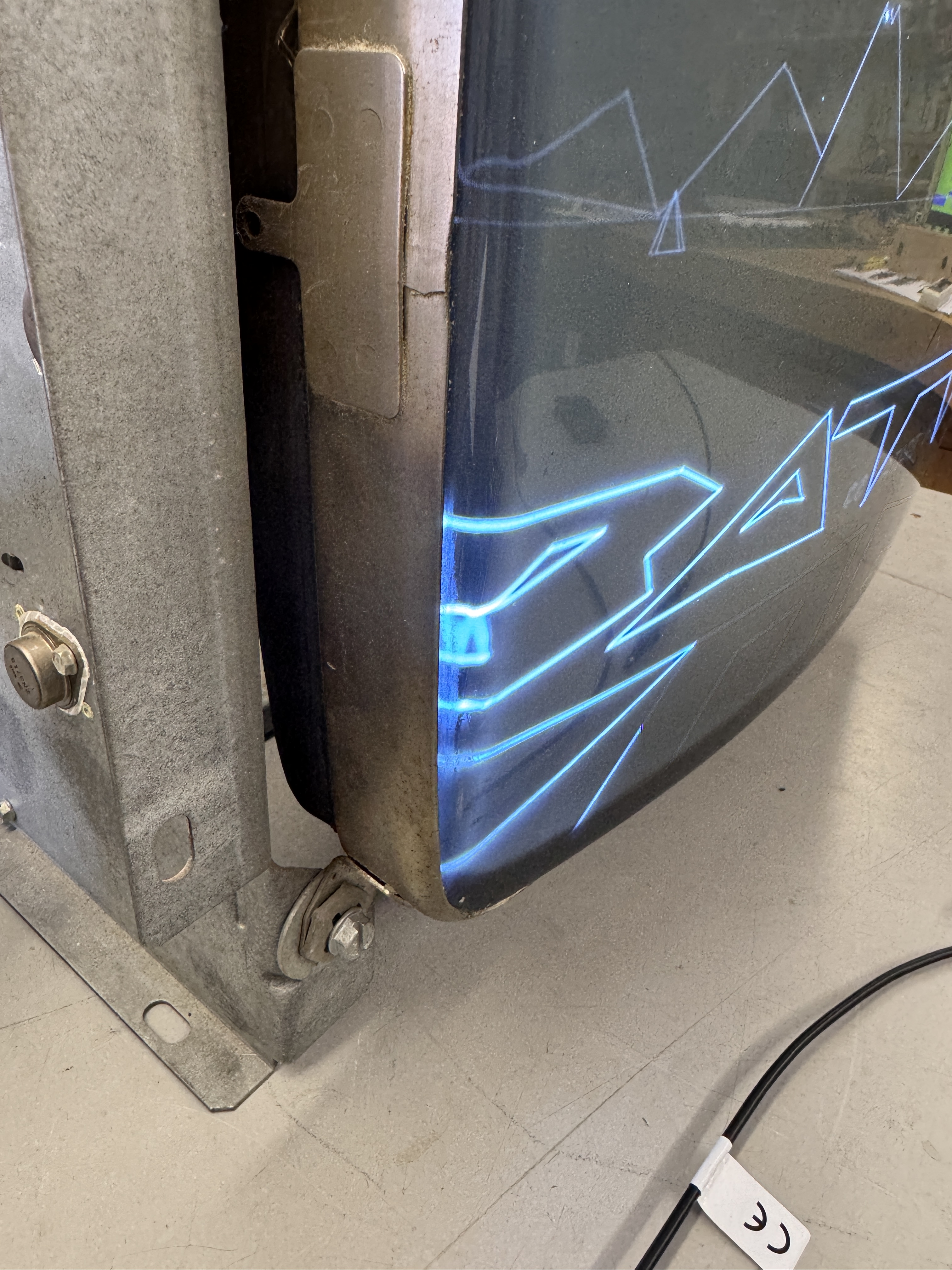
I’d shut the lights off to get a picture of the game running on the G05 – but this looked really cool. I took it just after getting the board running.
Board works!
Board #8 – Second board from my 3 board lot I picked up
Once initial inspection, cleanup, wash, chip legs cleaned, etc..
Issues:
- Missing crystal
- Needs socket repair/replace @N1
- Missing socket @D9
- Machine pin socket @E10 (will be replaced)
- Cap disconnected @C11
- VR3 – LM7815 missing
- R98 – X-Size pot broken
- Trace cut at the CPU
- Needed pins reflowed
- All ROMs missing

The worst part was this bad socket repair @N1. Prior work had destroyed all of the traces and this socket was hacked into position.
For fun, with no ROMs and all of that damage. Once I soldered in a crystal – board passed all the RAM tests!

Same for the ROM – except this mess below..

Jumpers were fed into the socket holes and the backside was all melted. Traces missing or lifted and each via had been pulled out.


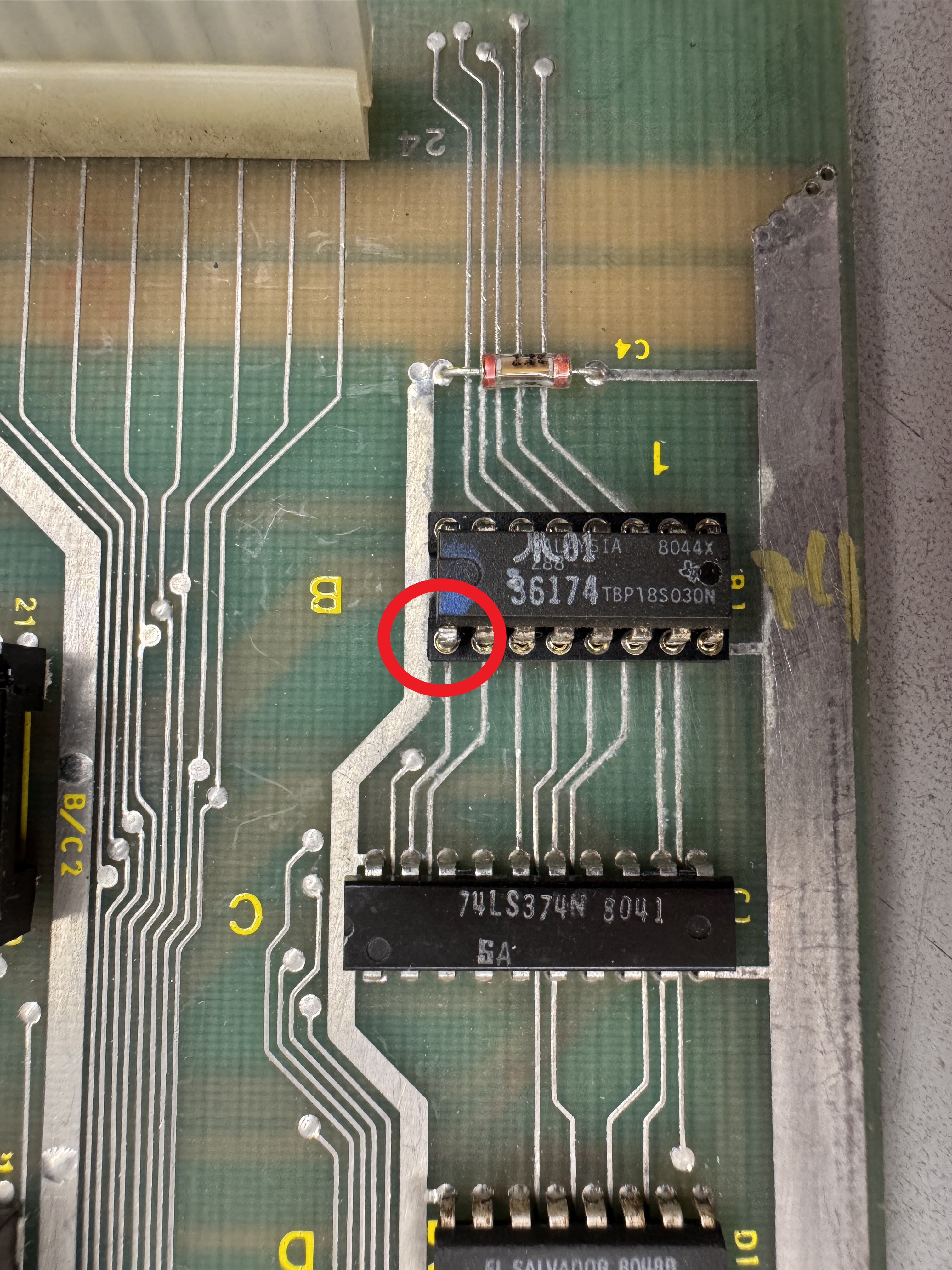
Here is the beginning of the repair work. It would probably have been easier to do this on the solder side. But I do not like solder side repairs – and wires at a corner would have been even more exposed. Each via ended up with a tiny Kynal ‘L’ (red circle) to connect the trace and stick out the back so that it could get soldered to the pin. Toothpicks keep the wire in place and allow room for socket legs.


I had to use a lot of flux to get the repairs to connect and beeped each one out as I moved along. Once they were complete I cleaned it up with alcohol and painted on a thick coat of UV cured solder mask. It does two things – locks all of the repairs in place to prevent further damage and most importantly – prevents them from disconnecting when soldering in the socket! The soldering has to move quickly to help that issue.

I like this type of repair over solder side work. It takes longer but I think it has almost no potential to get ruined since the wires are not exposed.

No issues with the repair.. Phew!
Once completed I moved on to the VG testing with the Catbox and all of the tests passed.
Moved on to the analog section where parts had been borrowed. Added sockets @E9 and @E10. I’ll be replacing the trimmer pots. Added in the VR3 – LM7815.
Once I got all of this in place.
Board works! I’m going to clean up some of that cap wiring in the analog section.
UPDATE:
One of the reasons I burn in boards for ~40 hours over 4-5 days is to shake out any weak chips. Board#8 failed in the analog section and I lost the X-axis. Socketed and replaced the analog switch @B10 and the X came back.
Connected to the monitor and the vectors would slowly shrink away. I’d catch the last of them just as the monitor was warming up.. If I turned up the brightness I could see it better.
Watching the image shrink away after a cold power up but not a board reset suggested it was a thermal issue. I got out the freeze spray to test in the analog section. With the brightness adjusted correctly – It was fun to watch..
Replacing the LF13201N @D11 corrected this problem. In fact, all 3 of these chips failed on this board. While there, I corrected the capacitor hack – which was factory it seems. Not sure why they did it.. The cap worked fine soldered into it’s correct spot. All the traces were there.
Board #8 – AUX Board
Technically it did not come with it – but it’s paired up now. It had two issues.
- Last bitslicer and it’s socket were missing
- Power LED didn’t work.

Power LED didn’t work because R37 was never installed at the factory. Not even a hit of solder.
Added a resistor, socket and a bitslicer. AUX board works!
Board #9 – Last board from my 3 board lot I picked up
I call this The Swamp Board. It may have been in a flood or something..

It is one of the cruddiest boards I’ve worked on. There looks to be rusted chips and some other surface issues.

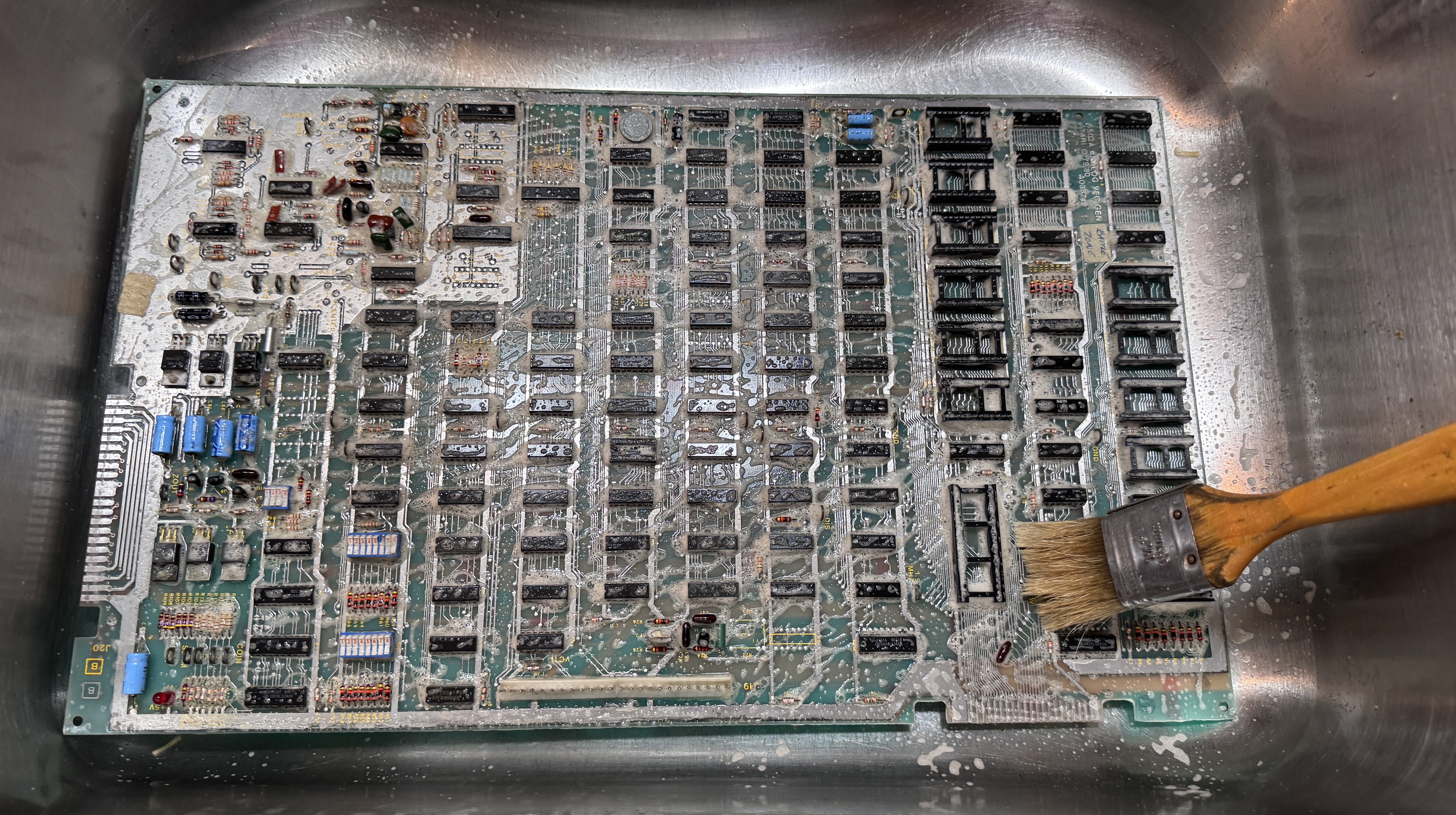
I enjoy getting all the crud off these in the sink. Makes them easier to work on and reveals any real damage. Even after this – it was still not looking as good as I would like.
There is still a lot of rust and issues on the 3-4 lower rows of chips in areas. When I first saw this board I considered it a 50/50 chance of being saved.. So I had an idea..
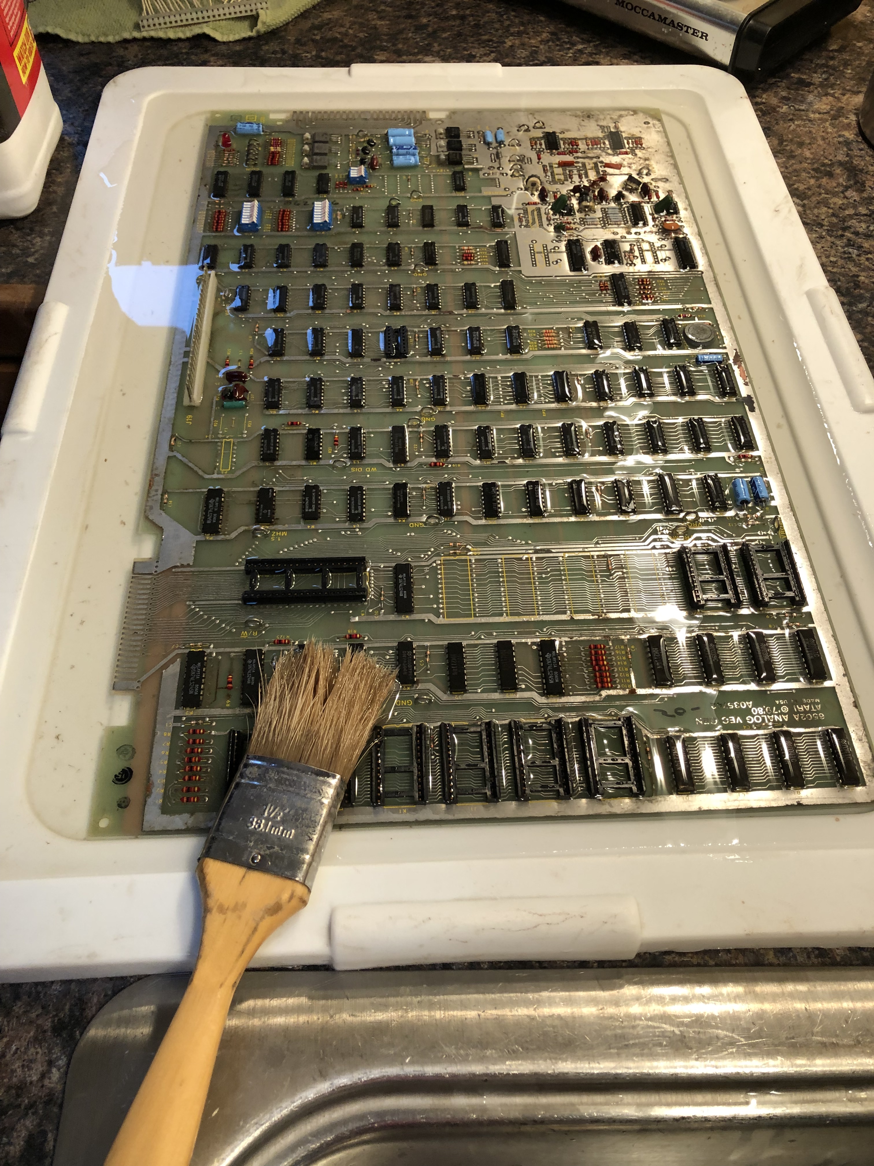
I used a container lid (I need to find something better in the future) and submerged the board in Metal Rescue rust remover for 15-20 minutes while working all of the bad parts with a brush.
This treatment did exactly what I had expected it to do. It caused all of the rust to be neutralized and any plating metal to flake off. It was already compromised and it really needs to be gone.
After brushing in the Metal Rescue, then rinsing, then really going after each chip with the air compressor I got the majority of the flaking metal off. With a few swipes of the fiberglass pen and a tiny screwdriver to rub any flakes between the legs off.. The damaged areas cleaned up nice and seem very solid.. The vast majority of the loose metal and flakiness is gone. Overall this board is in pretty good shape – no hacks or prior work like the last board. Except for parts that had been donated.
After final cleanup and a few pre-flight checks and adding a crystal..


A bunch of bad RAM and ROM all checked bad.. I’m pretty happy that it got this far!
Issues:
- Multiple bad RAM checks
- 5 ROM testing good off board
- 2 ROM tested bad off board
- Proms test good off board
- Missing DG201CJ @E10, D11
- Missing TL084 @C11
- Missing crystal
- Pins need reflow
- XBIP Pot busted
I’ve found on Battlezone that bad RAM will mess up the ROM.
RAM Replaced:
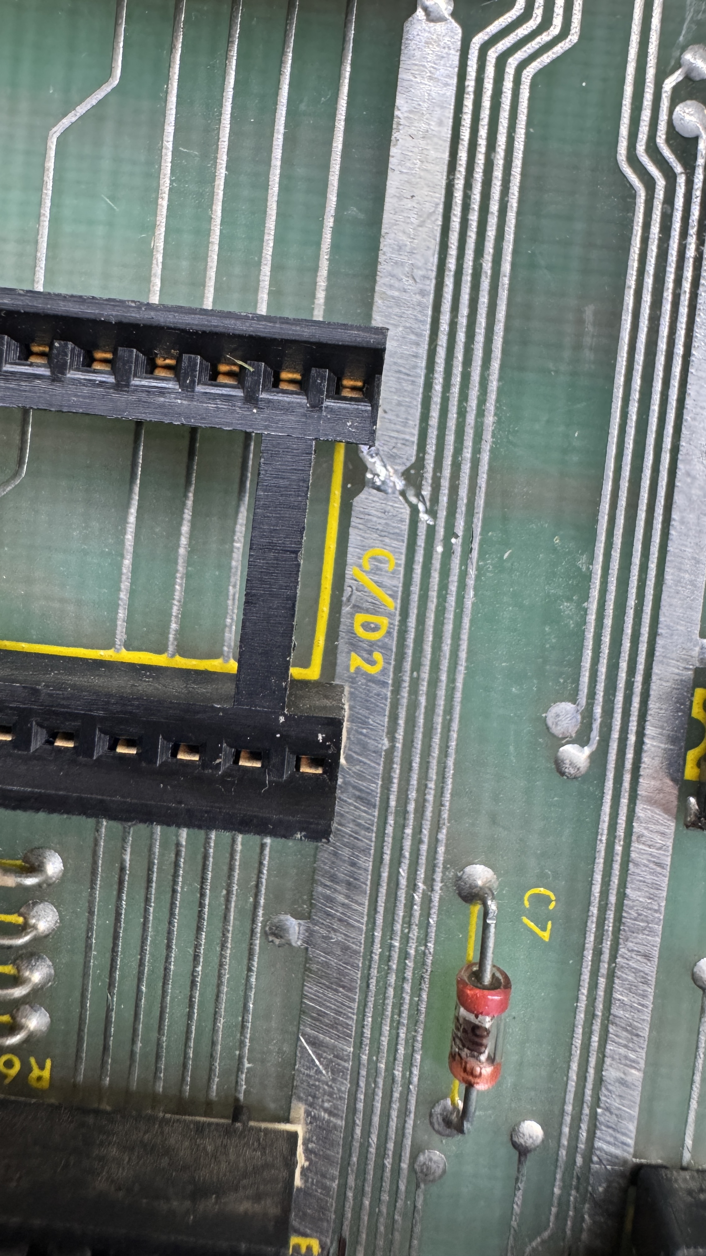
- Replaced @D2 – works – bad 4 bits
- Replaced @A1 – works – bad 4 bits
- Replaced @C2 – works – bad 2 bits
- Replaced @J2 – works – bad 1 bit
- Replaced @C1 – reported working, but the board beeped it out as bad.
As you replace bad RAM. Some of the other bits clear up due to the lines being stuck. Once all the RAM was up and running correctly. All the ROM checked good! Bad RAM was messing up the busses.
Connected up the probe for Vector Generator testing and quite surprisingly all of the test ran clean. Replaced the missing parts in the analog section.


Here is no XBIP pot on the left – Pot installed on the right!
Board works!
Need to pick up a matching AUX board at some point
Board #10 – Received a BZ in for repair. Owner sent the ARII – good thing!
Did a quick bench check and the BZ set was fine. The ARII was putting out 12v+ on the 5v side. Replaced R29, R30 which were visibly burned up, the LM305 and the 2N3055. Clean and test. BZ running great.
ARII Works!
Board #11 – Board in for repair
Only main board sent
Initial Inspection:
- All ROM checked good
- All RAM checked good
- Some prior work
- State machine shows 50% speed on some of the VG tests
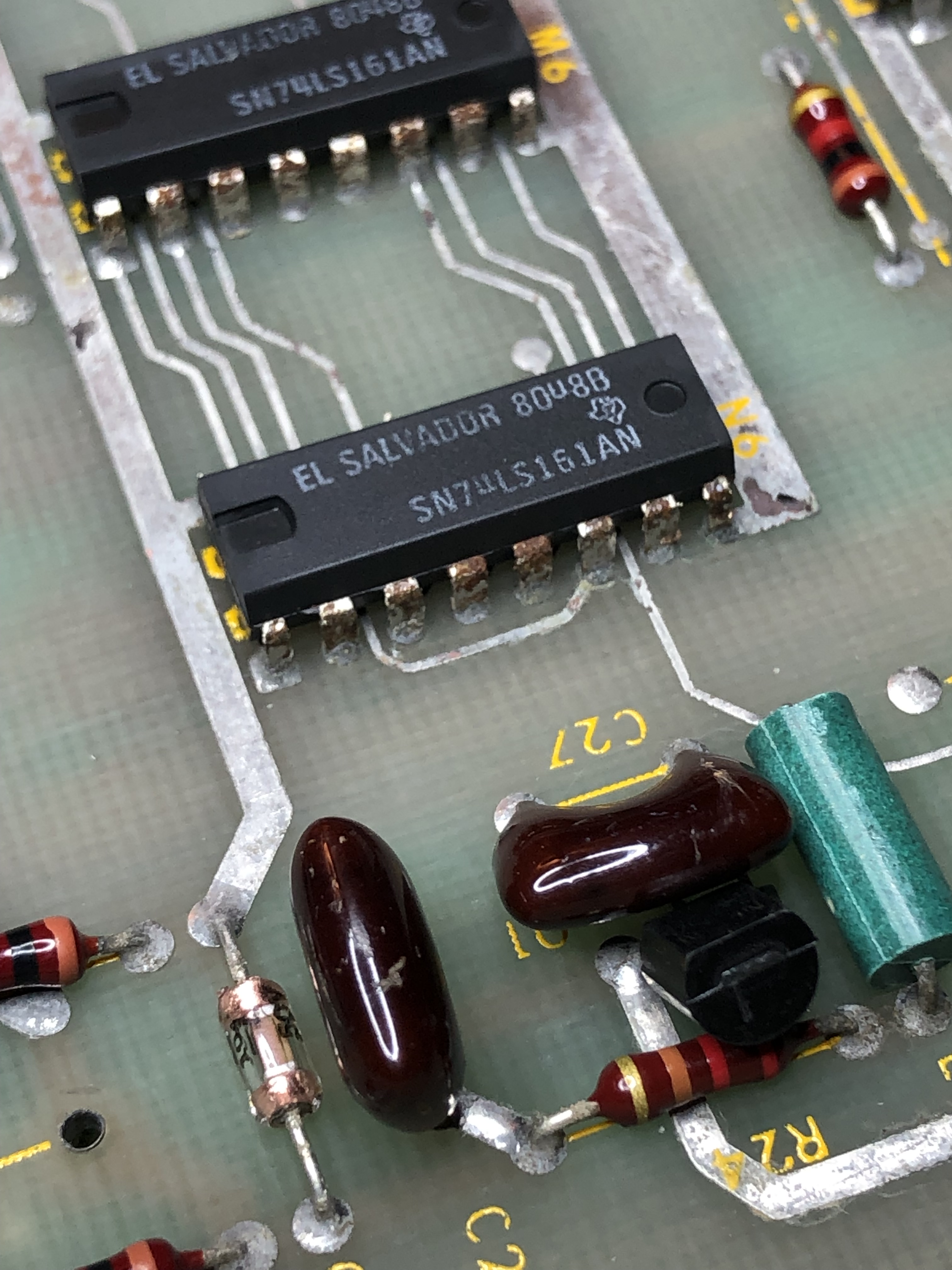
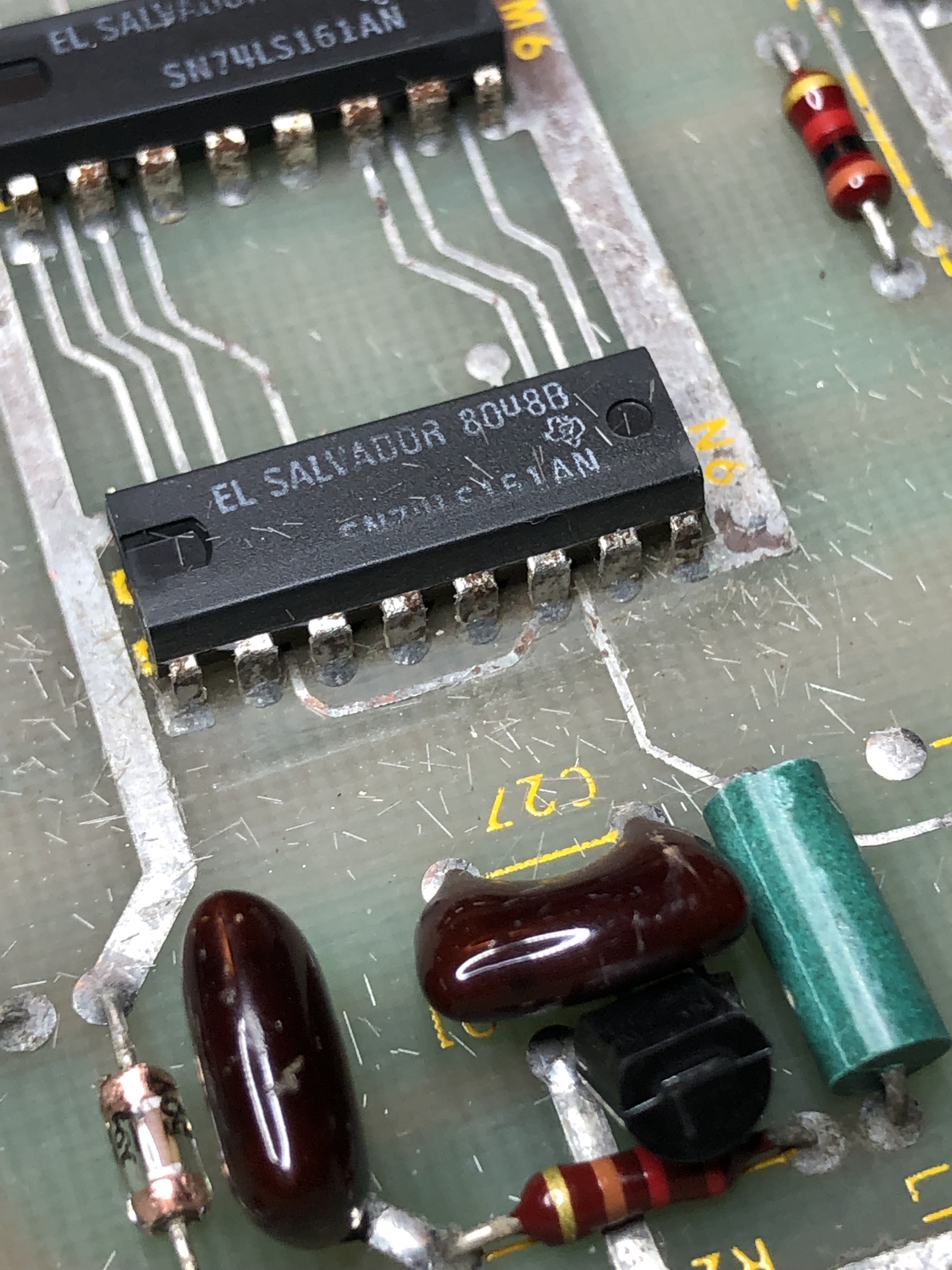
Piggybacking the LS161@M6 corrected the VG timing, replaced it. All VG tests now good.
On the scope, the X axis has a partial collapse. Replacing the TL082@A10 fixed this issue.
Once the game was up and running – random vectors started shooting around the screen after about 3 minutes. Put the game in test and it immediately beeped out a bad RAM@C1. I’m certain this board has not been powered up in a while. Socketed and replaced RAM.
Board will get a few maintenance items – couple of bad sockets, etc.
Board works!
Board #12 – Board in for repair
Sent in with a working AUX board. Pretty clean over all.
Initial Inspection:
- Bad 412 ROM
- State machine not getting to HALT signal
- Interconnect pins need to be reflowed
While cleaning all the chip legs, etc. Noticed that there was a 74LS161 installed in the state PROM socket @K6 – that’s not right.. Borrowed he correct PROM from another board. It did not fix the state machine. It was still starting, but not stopping.
Based on the labels OP0, OP1, OP2… and without researching, I’m betting these signals are to control the different opcode types of the vector generator. If they are messed up – the code doesn’t run correctly. Piggybacking K8 caused the VG timings to change. A good clue! I then used the logic comparator and pins 6,7 were blinking a bit. The comparator is a decent tool – but it is not 100% accurate. Finally I piggybacked and lifted the legs and compared them on the scope – they were different signals. Replaced LS175@K8 – all vector timings now good!
Game running, but had the exact same X collapse as the prior board – replaced TL082@A10
Final issue:
Those are some HUGE letters. I knew this was a scaling issue. Replacing LS175@F9 fixed the problem.
- Reflowed AUX board pins
- Cap @C29 was loose
- Replaced socket at B/C3 – was stretched out at some point.
Board works!
Update: On the 3rd burn-in round (about 26 hours total) the X DAC@A9 died.. Replaced. Back up and running.
Board #13 – Board in for repair
Actually 2 main boards were sent in to end up with 1 fully working set. One of them has the edge connector extension mod.. Not sure that it was necessary.. I chose the better of the 2 boards to repair
Initial Inspection:
- 8 of the 10 RAM had been socketed and replaced
- YBIP pot missing
Connected to CATBOX and Mask ROMS 414, 413, 409 were bad. Swapped them from the other board and the same ones were bad too? Put them on my reader and all 6 are no good. Most likely these were put in backwards. The printing is upside down (I’ve seen this a lot on these ROM sets) If you put them in reading the label vs. looking at the notch they are easy to put in backwards. They likely fried due to that..
Replacing them with good EPROMs – ROM and RAM checked good. Vector Generator checked good on CATBOX.


Here is what you get with a missing YBIP before and after. This is early in the analog section with the scope connected to pin7 of the TL082’s @A10, D10. I had horizontal collapse after this section. Replacing the analog switch@B10 fixed that and provided normal vector output.
Looked normal on the scope. On the monitor it looked exactly the same. The Z output was locked on. Probing around the Z had all the right signals, it just looked like they were not getting pulled down enough to blank. I piggybacked the LS399@H8 and it fixed the Z. Board was working!
Played for about 3 minutes and the entire screen started blinking off and on like a traffic light. I happened to put it into test and the 9th of the 10 RAMs died. Confirmed with the CATBOX – which had showed that RAM as good early on. Replaced RAM @C2. The RAM @C1 is the only original left and soldered directly to the board. I will socket and replace. It will die soon.

Other Items:
- Cleaned up prior edge connector repair
- Socketed RAM @C2 – it was the last of the originals and likely to die soon
Board Works!
Update: On the 3rd burn-in round (about 22 hours total) the LS164@P9 died. Lost Z-Output. At first I thought I had lost HV on my monitor. Replaced. Back up and running.
Aux Board:
Shows H&L Errors. I swapped all the bitslicers one by one and verified all the PROMs in my reader. Reflowed the header. Not going to be that simple…same issue.
After poking around the board for a while and basically determining there was no clock and/or bad clock – I put a good AUX board on and measured at the diagnostic pins clocks that were being generated at SACLK1,2,3 locations and comparing them to the bad board. I only had one of the 3 clocks.

The clock should be coming out @C5 pin9. I was getting strange output signals and decided to swap out the chip. No joy. Probing all the pins afterward – I noticed Pin10 had a signal on it.. Really? P,R22 – should be clean +5v.. A few chips in the area use the same power and all had 12KHz clock on the power… It was showing a perfect square wave. After looking for shorts, nothing..

I finally found the signal source – down in the audio section. The exact same 12KHz signal going into LS109@B4 AND powered by the same rail P,R22. There were no shorts between pin 12 and 11 or 15. So.. bad chip with an internal short? Yes. Replaced LS109@B4. The 12KHz signal was turning all the chips off/on.. Clean +5V now. Proper clocks restored. AUX board runs clean in DIAG mode.
Running the game.. missing sounds. The SHELL and EXPLOSIONs were missing. Replacing LS164@H4 – which appears to generate the noise – corrected the issue.
A day of testing later – LS164@H5 failed the same way..
Replaced power LED – it was dead too.
AUX board works!
Board #14 – Board in for repair
Initial Inspection:
- Power LED on main board dead (replaced it)
- Has the single ROM modification – no issues
Verified RAM and ROM on CATBOX.
VG timing to HALT was off. LS194 @C5 fixed the issue.
Running the board in game mode showed graphics glitches. Self test did not show issues with the AUX board. Verified all of the PROMs, no issues. Swapped one BITSLICERs at a time. BITSLICER @F2 was bad.
The sound seemed a bit off – AUX board had the wrong cap @C28. Replaced it and the sound is better.
Finally – Game stuck firing and turning right. Bad Pokey – replaced.
Board works!
Board #15 – Board in for repair
Initial Inspection:
- Board set very clean
- RAM tested good
- ROM tested good
- Vector generator stone dead. No HALT.
At first it appeared LS74@M9 and LS32@M8 were involved, but no joy.. After a lot of conflicting information I tool a step back and found that the board was in full lockdown reset. Exactly like I was holding the button down.

The LS393@M4 was not counting. Replacing it fixed the lockup.
Now I’m getting a little bit of HALT, but the timing is way off. The LS175@F9 was involved – but again no joy. Traced it back to a floating Pin8 on LS08@L5. VG fully up and running now!
Game ran on the scope – put it on the monitor in test – bad Mathbox. Replaced bitslicer@/E2. Ran the board a few hours and the 36180 PROM died.. Replaced it.
Finally 6 hours into burn in – LS161@L6 died.
Ran full 40+ hours of testing after this.
Board works!
Board #16 – Board in for repair
Initial Inspection:
- Board set clean
- Edge connector in bad shape – lots of goo and stuff on it..
- Bad RAM @B1
- ROM tested bad
- Vector generator good.
- AUX board no power LED
After cleaning the boards, legs and the edge connector..
Strange readings from the board. Tester showed 4 bad ROMs. My GQ4x4 showed 3 of them bad and after putting the machine in DIAG mode it showed another 3 bad that read good on the bench. In the end – 6 of the original mask ROMs were bad and I replaced the 7th just because… There was an original Atari Ceramic ROM (036414) that worked and I left it. Ceramics are normally pretty tough.
2 of the RAM were reading flaky during all of this. They got socketed an swapped.
The pin headers on both boards had cold solder joints. That cleared up some wonky graphics. I also replaced the dead power LED on the AUX board.
Ran great for days and the graphics got flaky on day 4 of testing only during power up from cold. Took some time to rack down because it was very intermittent. Turned out to be the socket on the bitslicer @D/E2 on the AUX board. The Atari golds have been good to me. It was a surprise that it was marginal. Ran solid ever since.
Board works!
Board #17 – Board in for repair
Initial Inspection:
- Board set clean and unhacked
- Has High Score Saves kit – removed for testing
- Bad RAM @B2 – diagnostics beeped it out
- Vector Generator running very fast
Pulled a known set of good working EPROMS from another board and removed High Score Saves Kit. Replaced the bad RAM@B2.
Initially I was able to see a HALT running – all the other VG commands were running fast, like they were starting and finishing immediately or the vector timer was getting bypassed. I could get the game to play blind – but it sounded off.
I spent considerable time poking around trying to determine why the VG was so corrupted. Didn’t seem to be getting a proper GO signal and I traced backwards from there.
I kept going back to the timer/controls area as it seemed this was where it all went off the rails..
Just to be sure – I replaced the LS161@K6 and the LS32@M8 looking for a change.. No joy. The LS109@N8 was also a factor and I removed and tested it.. Also not an issue. Had to keep backtracking in the circuit.
The breakthrough was the OP0 signal was messed up. I probably should have found it sooner.


Pin 15 is an output for LS175@K8 – magic clock!.. ok.. so there is a short someplace.. or a bad chip.. At this point the schematic is not so useful and there doesn’t seem to be a 2.41982MHz clock designed onto this board.
From here I pulled LS27@N7 and the state PROM – still crazy signal @K8 Pin 15. Started searching for crazy clock signal and found if coming from here:

Here is LS74@M9 pin 12. There is a tiny short to the trace that looks factory.. Except this board worked at some point.. is there such thing as solder creep? It wasn’t a flake. I had to heat it to correct it. Once I separated those two.. a big section of the timer circuit started working.. but the trace still had the crazy clock AND it still was still on K8 pin 15.
The shorted trace continued to LS02@K9 pin12 – this was connected to the LS191 counter @F10. The LS191 was putting out the crazy 2.41982MHz signal on pin12.
The path back was from the LS191@F10 P12 to LS02@K9 P12 which is an input.. It then came out of the LS02 on P13 .. Its output.. which then followed the trace that was shorted to LS74@M9 pin 12 which finally went back to LS175@K8 pin 15.. It corrupted SCALE, OP0 and all kinds of stuff. But on the output side of the gates. It wasn’t a simple 2.4MHz signal anymore which made it so difficult to find in the first place.
Got all that?

All of this was running all over the place through gates, etc. and getting modified along the way. Once I found and fixed the 191 – I thought I had it, right?
No – everything was cleaner – but still messed up.. Burned more time until I pulled the state PROM from the socket and determined I folded a leg.. Grrrrr … The state machine was messed up until I pulled the chip again thinking maybe it died.
This one was trickier than most because of the double sequential failure. Bad clock into a short. If fanned out all over the vector generator. Somehow they are likely related..
Board works!
Board #18 – Board in for repair
This one got all of the standard board maintenance work. Once I got it connected up, I noticed that vectors were unable to be drawn on the X-axis. I searched around for a while and it seemed like latch3 off of LS42@J7 should have been firing. Logic testing showed it should.
I replaced it (seemingly with a stronger chip) and I could see the negative pulse being pulled up by a short. Unfortunately latch3 ran all over the board. Any number of chips could have had an internal short messing up the signal.
Fortunately:


Upon VERY CLOSE inspection I found these. Shorts corrected.
Board works!
Board #19 – Board in for repair

This set has a lot of miles on it. It’s been in a few different shops over the years. I’d already removed some of the tags and stickers that were in the way and obsolete. Hadn’t not got to cleaning and maintenance, but I wanted to see what was going on with it. It’s been a little while since I worked on a Battle Zone.
It came with the Braze kit and no ROMs. First thing I did was put it back to factory so I could test. When I connected, all the RAM and ROM checked and even the vector generator checked. It seemed like it was playing blind once I put it back into game mode.. but it crashed pretty quickly. I was looking it over, inspecting, etc. and the whole thing died. Happened during the first 10 minutes of power on.
Quick check and no clock. Really?

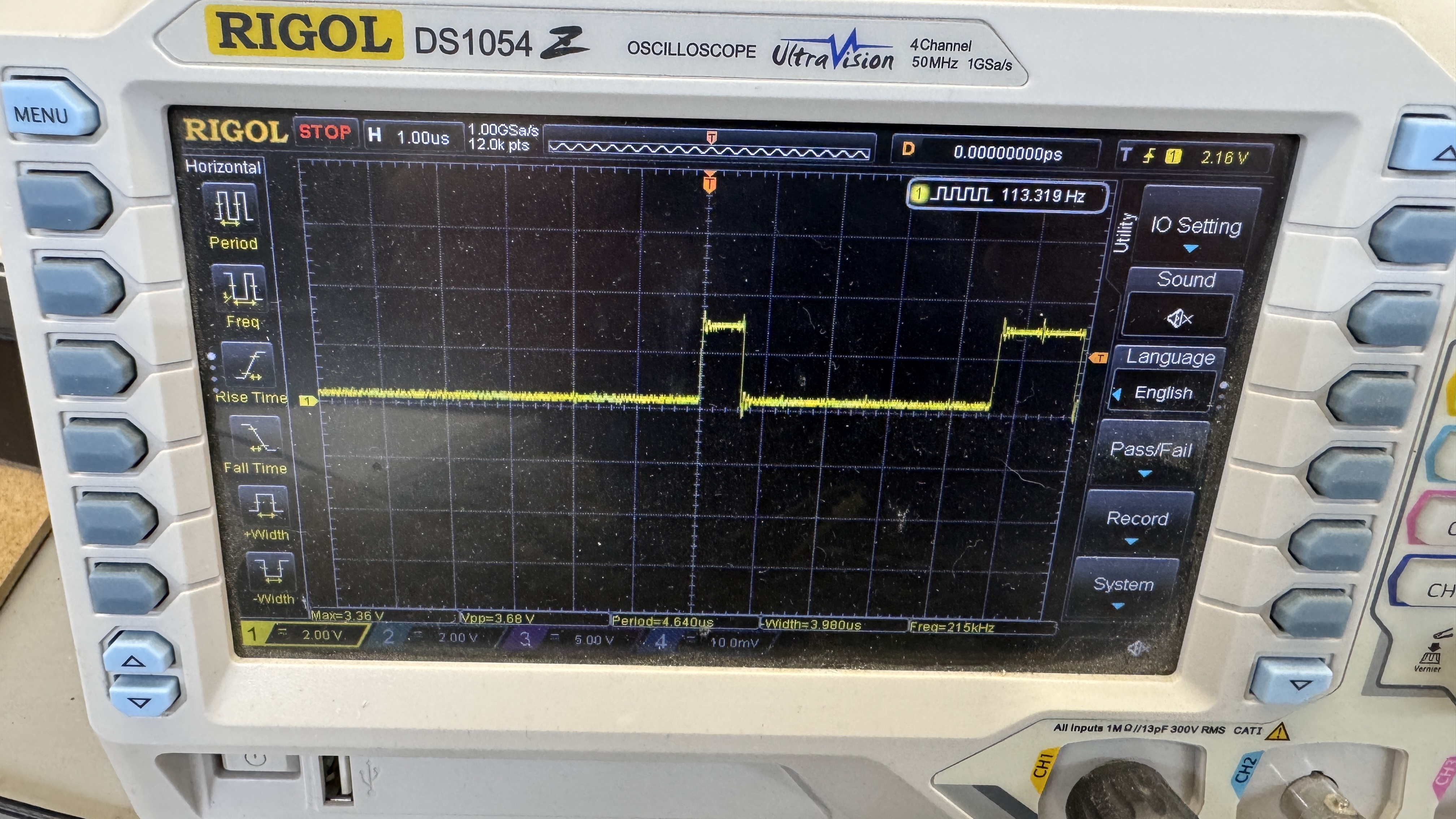
I started at the crystal and worked my way out. 12MHz into 74S04@R9 Pin 9, nothing on Pin 8. Replaced it and things got crazy..
The output of Pin 8 was the above?! The pulsing was synchronized with the watchdog. If I disabled the watchdog the 12MHz clock would stabilize on the smaller (low amplitude) version of the clock. None of this was happening before. Maybe I shorted something putting in the new 74S04?.. Maybe a solder splash went someplace? Shorted pin on the back? I looked for all of this stuff .. nothing.
Clearly the clock is shorting to the watchdog circuit.. Turns out the 12MHz signal is used in many places on a Battle Zone board. I counted 10. The initial plan was to find chips that had a connection to RESET AND 12MHz.

RESET basically turns into DISRST @L5 and was now in the picture. It was toggling with the watchdog as expected. Checking all the chips that had the bad 12MHz clock or the suspected DISRST signal led me to this area..
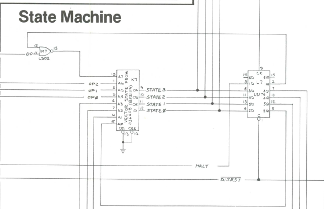
74LS174@L7 had the reset toggle at Pin1 AND it was showing the corrupted clock signal on Pin6 (STATE3) Luckily the state PROM@K7 is socketed. Pulled it out and good things happened. The original corrupted clock at the beginning of the circuit on 74S04@R9 was back to normal. Pulling the state PROM broke some connection and the bad signal still existed on STATE3. The LS174@L7 was sorta suspect.. but it didn’t have the 12MHz clock coming in.. however..
The LS74@L9 had STATE3 and the 12MHz clock. I diode checked Pin1 and Pin3 – dead short between the two. The 12MHz clock was getting toggled by the watchdog circuit and corrupting everything. My guess is that it took out the 74S04@R9 in a cascading failure. RAM, ROM and vector generator back up and running.
Last item up is this vector glitch:
The symptoms were pretty specific once you recognize them. The only glitchy graphics were the 3D ones, but more important the glitch was very consistent. Hit reset and the glitch happens as the tank pans over the first pyramid. It was behaving like an AUX board issue – swapped one in.. not the problem. It also seemed like it could be a RAM issue, but I could not effect the glitch with a piggyback.. The board had a Braze kit – tried it. Same glitch and no diag items popped up.
Realized I had not yet swapped the ROMs at A3 and B/C3. Problem solved. ROM@A3. ROM did not fail in self test or with Braze. Verified clean on the bench/ROMIDENT. It only glitches under use at clock speed. It was an original MASK ROM.
Board works!
Board #20 – Board in for repair
Board is in pretty good condition, but had a few issues. Once cleaned up and tested. ROM addressing was not working correctly during testing. The CATBOX was confirming incorrect ROMs and pulling one would make 2 go bad etc.


Look real close – pin 14’s address line had been cut at some point. Repaired with a small Kynar wire locked in place with UV cured resin. There was also a cut trace/repair with a jumper on the AUX board. I removed the wire and repaired the same way.

Many Battle Zone boards have cold solder joints – this one was no different. The state prom was in backwards. Board works!
Board #21 – Board in for repair
This was a relatively clean Battle Zone. Reported to have an “L” on the diag screen and the game wasn’t running. Notable is the ROM with a broken corner and the copper showing through on the edge connector.
Did all standard board maintenance, reflowed the headers and replaced the pots. Cleaned up the edge with Rust Erasers to polish it smooth, alcohol to clean and Liquid Tin to coat the copper and prevent it from oxidizing.
Re-tinned edge connector. Really clean looking and no solder blobs. Interesting way to ‘not replace’ the PROM sockets. Used machine pin sockets to stretch the contacts and reseat the PROMs. Seems to work fine. The ‘L’ issue with the game was due to a bad 036176 PROM on the AUX board. Replaced it..
Board works!
Board #22 – Board in for repair
Game would cut in and out. Issue is the Atari gold pincher sockets on the CPU board. Replaced all 6 – which was a colossal pain. The did not want to come out or clear. Took a couple hours. Nice new dual wipe sockets.
Board works!
Board #23 – Board in for repair
Got a Battlezone to work on.. This one had some typical failures and an interesting one..


Very common is cold solder joints.. One I haven’t seen is the tops of all four bitslicers blown off identically. Seems like a manufacturing issue – these chips always get pretty warm. Maybe there was an air pocket or a bit of moisture in them? I never powered them on, but they got replaced.
After that – the CPU board was ‘unstable’ at best. This was a socket issue and I replaced all 9 sockets on the CPU board. These were the Atari gold pincher sockets which can be pretty hit or miss. After full board maintenance, burn in testing…
Board works!
Board #24 – Board in for repair

Similar to the prior board this one needed/got standard full board maintenance. Plenty of cold solder joints and a bent leg on a ROM. This one also needed all of the sockets replaced on the CPU board. Once completed..
Board works!
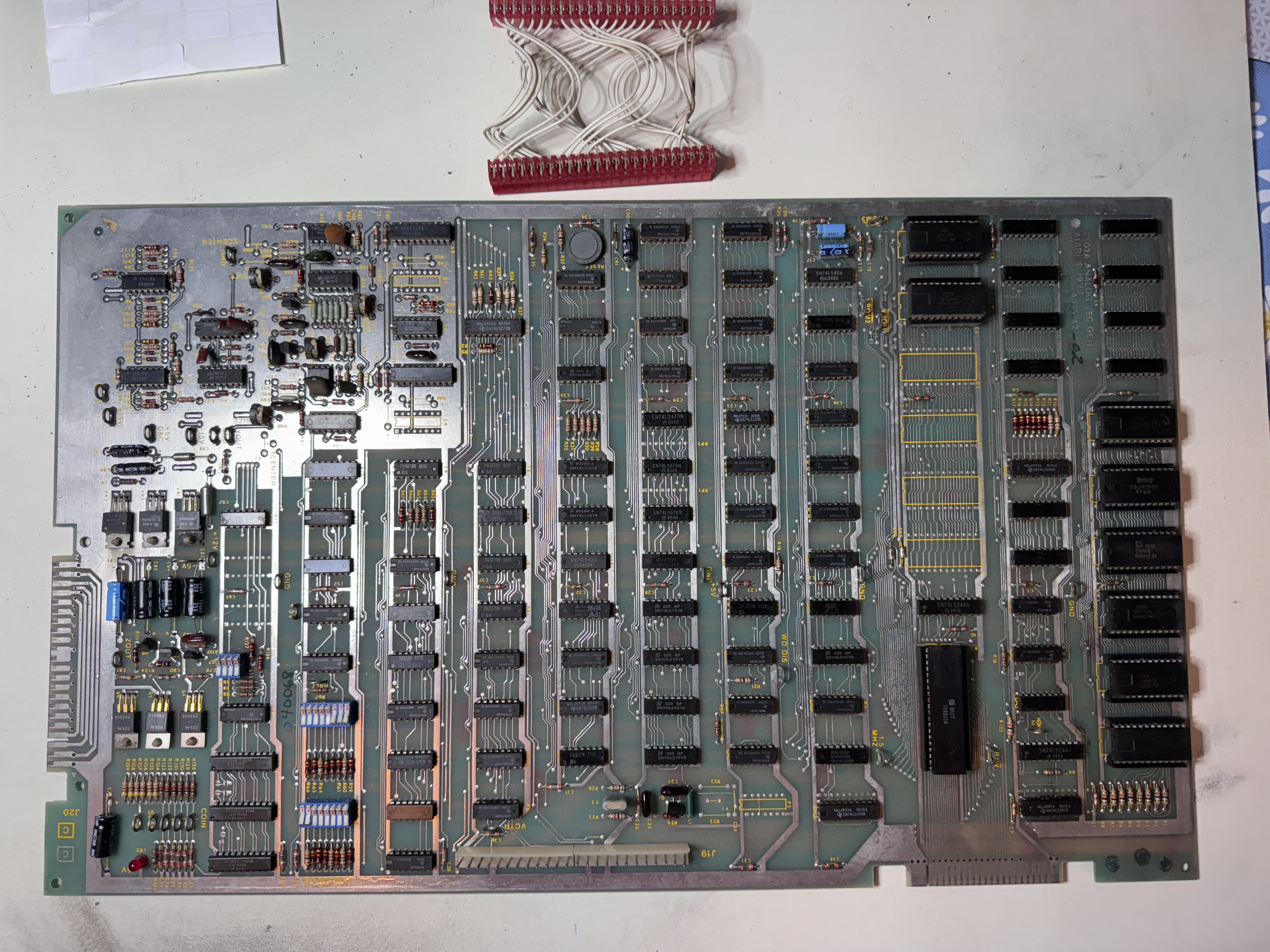
Board #25 – Board in for repair
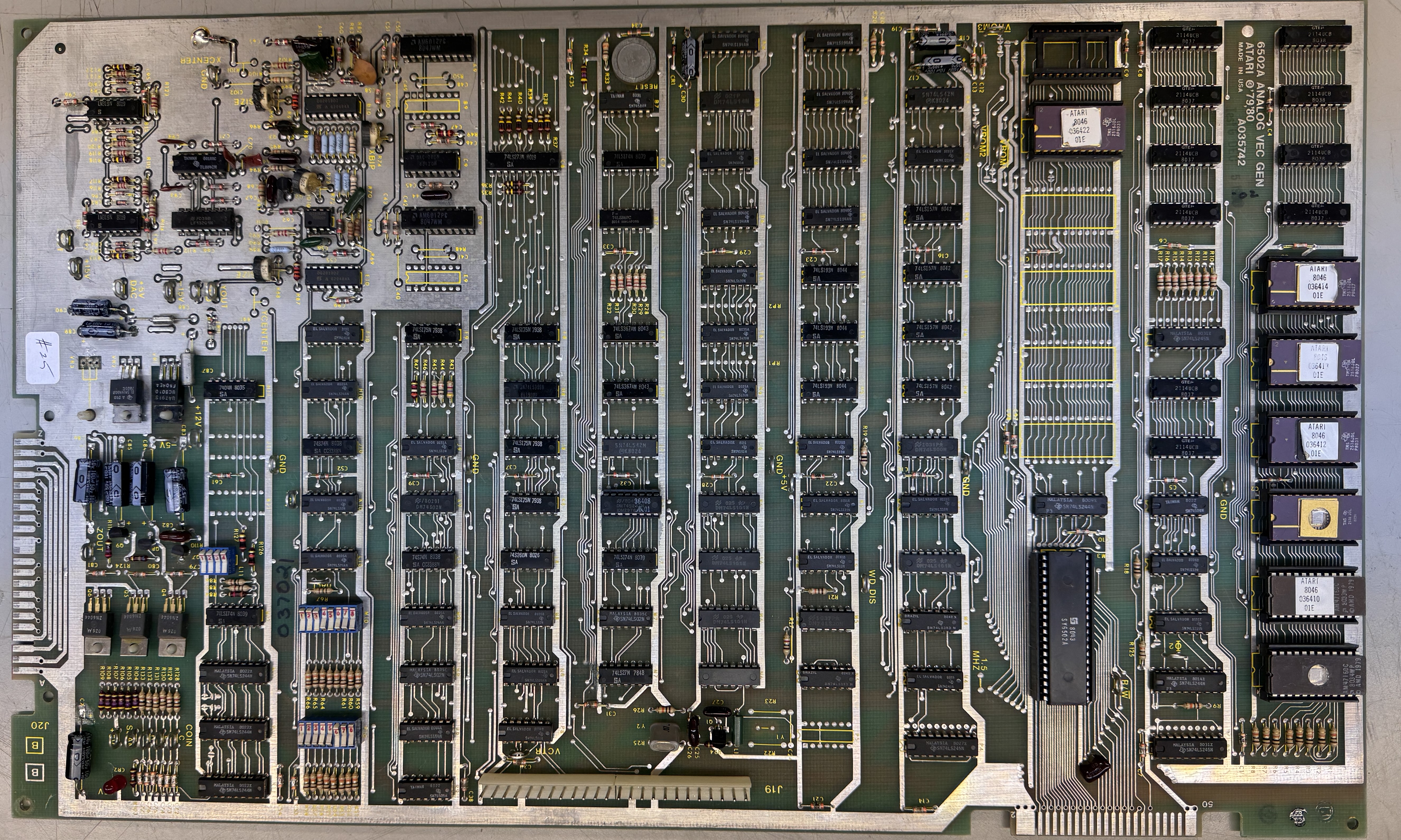
Received a Battlezone. Board reported not working. When I received it the ROM@A3 was missing and the 7815 voltage regulator@VR3 was missing. There was prior work – boards had been recapped.
I started by removing all socketed chips, cleaning the legs, Deoxit, etc. replaced the missing voltage regulator, burned a ROM@A3 and inspected the board. Checking voltages the 15v was being shorted to ground and the new regulator was getting hot.. Thankfully 15v goes far few places than 5v when it comes to shorts..


Once the 15V issue was corrected, RAM, ROM and the vector generator checked as working. There was another solder bridge that was effecting the graphics and a small .47pf cap (C104) that looked good was broken across the TL082@D10. Replaced all of the standup pots with sealed cermet pots.
Board works!
Board #26 – Board in for repair
This one was sent in reported issues around no Z output and graphics issues. I ran it over 30 hours in various ways and could not get it to fail. I did replace all the pots in the same way I outline on Board #27 below.
Board #27 – Board in for repair
This Battlezone may be the newest looking board set I’ve ever seen, but it had been worked on in the past. On initial inspection..

There were some cold solder joints at the header pins. I wire wheel them to shine them up and reflow. I also did my standard board maintenance removing all the chips (which were clean) .. buffed up the legs and Deoxit them and the sockets, then connected it up to the test harness.
Game was running, but had a couple of issues.
My first major issue was the windowing circuit was not working. You can see the Battlezone crawl drawing on the side of the tube and reflecting back against the phosphor. I probed around with the scope for a while trying to find this one.. It did not readily present itself or I kept missing it.

I finally happened across it here, the 74S86@B7 – Pin 11 was bad. Replacing it restored the blanking window. It was a ceramic chip, which is why I think I kept overlooking it. They tend not to fail as easily as the plastic ones.
Next up was this issue.. this one took a number of days to narrow in on..
While it was warming up for the first 45-60 seconds.. the busy part of the attract screen would get jumpy graphics. It took a while to identify all of the specific symptoms. I only had less than a minute to look for the cause before it corrected itself.
Normally I would use freeze spray to locate a bad chip, but I was out and 5 days after ordering.. it is still not here! I tried the ice cube in a baggy trick, but it didn’t work in this case. I tried to power cycle the chip into failing using a smart plug automation – power on 10 min, power off 10 min – 60 times! No joy.
I spent the majority of the time in the vector portion of the circuit. Using a DIP pullup / pulldown clip – I targeted a 74LS74 that if I pulled up its pins – would induce the jitters.. but it wasn’t the chip. Progress was slow without freeze spray.. But then I decided, put the board outside for 15 minutes (28 deg in January). That worked! At least I could chill the board and create reproduceable failure. It was something that was marginal. Piggybacking the 157s, 191s, 175s and a few others wasn’t helping. But all of the testing made me observe that it would get the most flakey when there were a lot of vectors. This suggested it was potentially a weak RAM when cold.. My thought was the vector program got high enough in RAM and would lose a bit while cold (or something to that effect). All of the vector RAM is original and was soldered onto the board. Piggyback process didn’t do anything, same failure.
The only RAM left was the program RAM – they were socketed – popped them out and put 2 x 2114s in…. problem solved.. seriously? The program RAM must keep a lot of vector data it seems. They were both the correct speed RAM. I tried something and swapped the two of them just to see if it made different jitters, but the problem went away.. very odd.. swapped them back and the jitters returned.. They both got replaced.
Last item is the owner wanted the X and Y centering pots loaded.
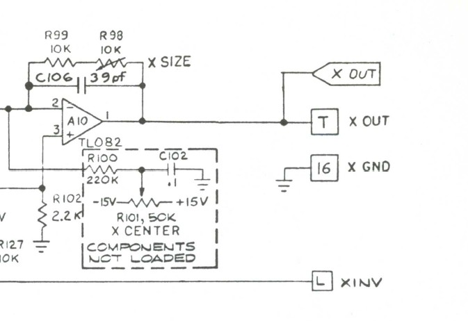
Atari didn’t load them and I’ve never even looked into it.

A 220k resistor, .1 uf cap and a 50k pot and it works great..
Board works!
Board #28 – Board in for repair
I tried powering this one on before doing any work.. Board wasn’t having it.. Tested RAM and ROM. Board showed bad ROMS.. reseating them would get them to validate, but it didn’t take much to get them to fail.. They all went in and out very ‘crunchy’.. Board has the old Atari gold pincher sockets. All needed to go on the CPU board.
Here they are all removed and prior to a little cleanup before installing new sockets. Nine in total including the CPU. Takes a while to get though them all. As with nearly all the vectors, I replace the stand up pots that are easily broken with sealed cermet pots.

Plenty of cold solder joints on the header pins too.. These get wire wheeled and reflowed. Once it was all back together..

Board works!
Board #29 – Board in for repair
Reported not working – solid LEDs. Confirmed – it was stone dead.
Connected to my tester and it showed no ROM and missing bits on the RAM. After a bit of testing and checking I pulled some ROM out.


Under a couple of sockets, this was present. I cleaned this up and got the board to boot. But I’m certain it was caused by lack of reliability. I could get the board to crash by flexing it and all of the socketed chips were oxidized. From here I did my standard – remove all chips, clean legs, Deoxit and reinstall.


This is after wire brushing, you can see the cold solder rings cleanly on the interconnect pins. They all got reflowed.
I replace all of the standup pots on Battlezone. Recently I’ve been adding the X and Y position pots to the factory spots on the board that were not loaded at manufacture time. Normally you would adjust the picture by turning the rings on the back of the monitor and they should be use for coarse adjustments. These pots allow a little fine tuning once it is set.
Board works!
Board #30 – Board in for repair
Reported symptom – just a blinking line on the screen occasionally.
I connected up the stack to my test rig and confirmed, the board was not running.
I generally clean all the chip legs and inspect the board once I know it is not working. Sometimes I get working sets – so best to plug them in first. I remove all the chips, clean the legs, Deoxit and look for physical issues.

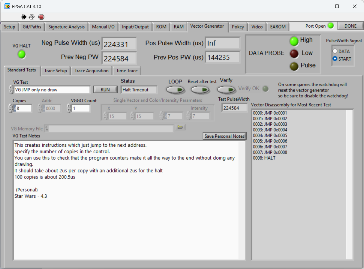
Once it was all back together, I connected to the FPGA Tester and checked RAM and ROM. No issues. Checking the vector generator – nearly all the tests worked except a couple. After looking at them, the tests with a lot of vector code were the ones failing. Using the JMP test – I found (on the left) if the program counter was 7 or less – no problem. Neg Pulse width was 16us as expected. Once it went to 8 – the VG failed.

I spent a little time in the program counter area since that is where the issue obviously was.. I figured it was LS193@H5 since (if it works the way I think it does) address 8 would be AVG4. On the scope, AVG4’s signal looked like it was being pulled down. Running the test in RESET after test and failure mode – a quick piggyback of H5 did nothing – but a piggyback of the LS157@F4 caused the pulse width to glitch. Didn’t fix it – but often times that’s all you need. Just find the chip that glitches a bit..

Replaced the LS157@F4 – boards started working.


The edge connectors had been cleaned a lot and the copper was showing though. I cleaned them and re-tinned with liquid tin. The stuff works great.
First overnight test – The LS157@H4 (next in line) failed. Same date code. I replaced all 4 of them in the address selector circuit. All Signetics and it was just a matter of time before they all failed. I’ve started adding the centering pots to Battlezone. Makes them real easy to adjust. The TIP102@Q6 was missing.. I put one in – even if the coin counter is likely not used.
Board works!
Board #31 – Board in for repair

Board came in reported to have graphics come and go.. Sometimes I repair them first and do board maintenance second – other times – when I’m at lake for the weekend – I clean them in the AM with coffee and YouTube and repair them back at the shop. Battlezone got cleaned at the lake. Removed all the chips, cleaned the legs, Deoxit legs and sockets and put it all back.
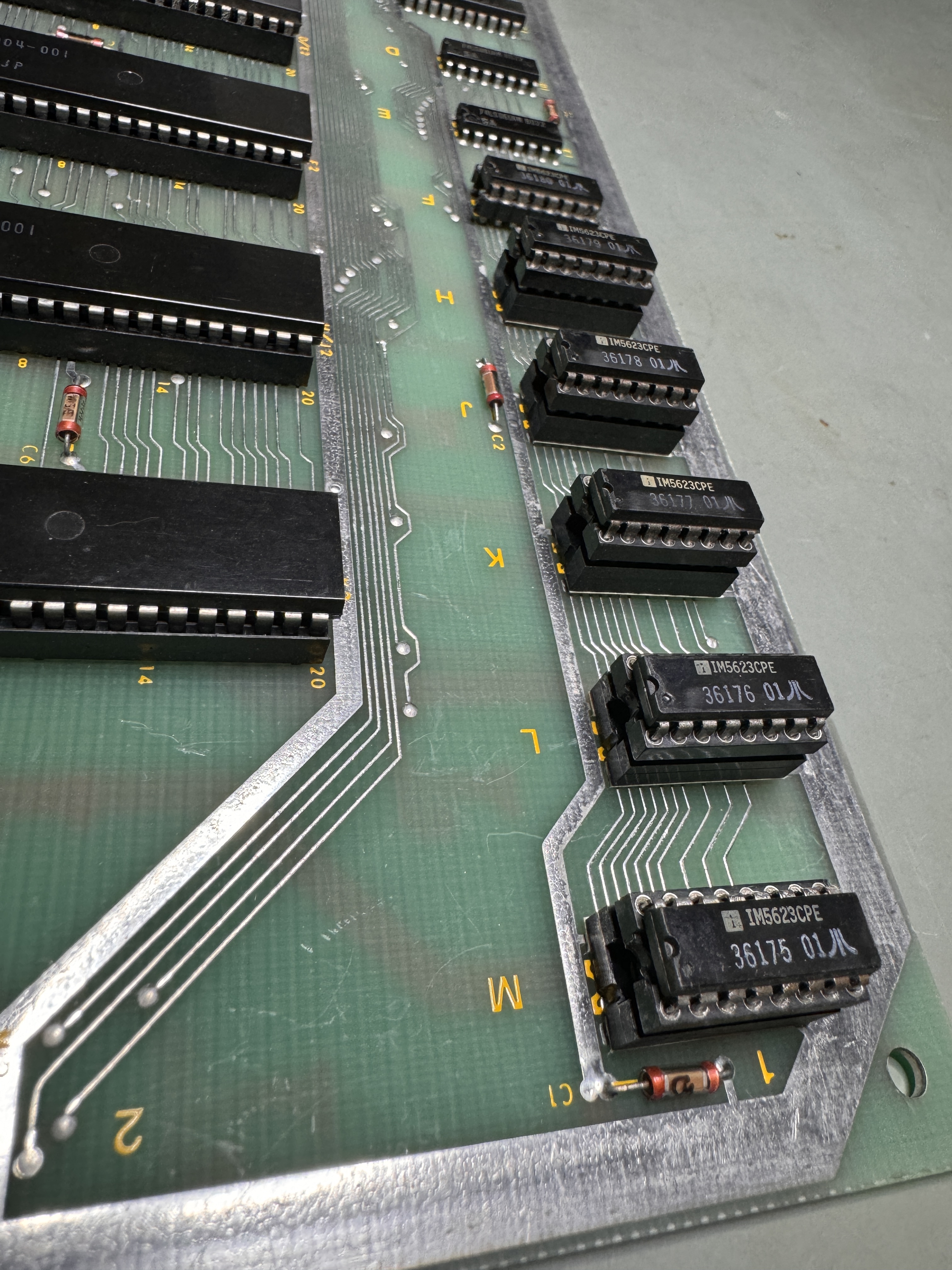
During all of this – it was very clear that the PROMs on the AUX board were very frail. They had been cleaned in the past of tarnish.. but a number of legs flaked off..

Some of the legs broke off so that I could solder a new on onto the stump. The corners on 36179@H1 broke flush with the package. I have a Dremel bit that I can cut away enough plastic to expose the leg inside the package and then solder on a new leg and add UV Cured Resin to reinforce it.. The remaining legs all seemed pretty strong. PROMS cost too much to replace ($15+ each typically) so they were worth saving. Spent some time repairing and replacing all of those legs.
Battlezone also has the standup pots that fail and can cause many graphics issues. They all get replaced with sealed pots.
After that.. Ran solid for 30+ hours spread over a week
Board works!
Board #32 – Board in for repair
Reported symptoms were graphics issues and always having something going wrong with it.
The edges were heavily solder blobbed.. Have to remove that issue since it would damage my test rig.
Here the solder is removed and the edge polished up as far as I wanted to go.. Next I coated with liquid tin. They look a little blotchy in the lighting, but they are near perfectly factory smooth.
Inspection and chip cleaning is next..
This trace smear turned out not to be an issue, but it is one of the things I look for. Lastly I remove all of the original stand up pots and replace them with sealed ones. I also ADD X and Y centering pots which were in the original design, but not installed on the final release of the boards. The allow you do adjust the screen without having to mess with the rings on the back of the monitor.
Checking with the owner.. to me.. this has to go.. I can put a good button switch on the PCB. The actual issue with this was a bad RAM@J3.
Board works!
Board #33 – Board from a friend
Friend brought this because he could not find why it wasn’t working correctly. We connected to the FPGA Tester and found some of the vector generator tests the timing was off.
RAM tested good, ROM tested good – self test showed no issues.. I spent time poking around the VG and even changed up the test code a bit to see if I could determine if it was a specific instruction that was failing. There wasn’t a real pattern to it.
I did find low voltages coming it out of the STATE PROM.. and swapped it and the chips around it, but no change.. Used SLICE on the address 157’s.. they all were doing what they were told. The one thing I had not done was mess with RAM.. Piggybacked RAM@A2 and the VG test that was failing started working and the RAM test on the FPGA Tester failed, weird.. Replaced RAM@A2.
Board works!
Board #34 – Board in for repair
This set came in with a spare AUX board. At this point I had already done a bit of testing to see where I was starting.. Nothing worked.
Using the FPGA Tester, nothing really was responding. RAM and ROM were reading bad until I pulled all the ROM. At that point the RAM tested good.
The header pins all get wire wheeled and reflowed. You can see some pretty bad cold solder joints almost all the way across.
The sockets were all pretty crunchy. I could tell I would have issues if they were not washed. Krud Kutter does a great job cleaning the metal. Here I had already removed all of the standup pots.
Once I got it all back together after cleaning all the chip legs and Deoxit’ing all the legs and sockets, 6 of the ROM tested bad. They were all mask ROM so I had to burn replacements. Got the RAM and ROM verifying, great!
Testing the Vector Generator – no HALT. (shocker)… Because the VG is a giant circle – it can be difficult to find the cause.. I spent a while hunting this one down.
Eventually I found that the 7474@L9 was the cause of the no HALT failure. Replacing it got all of the VG tests running, could this be it? No..
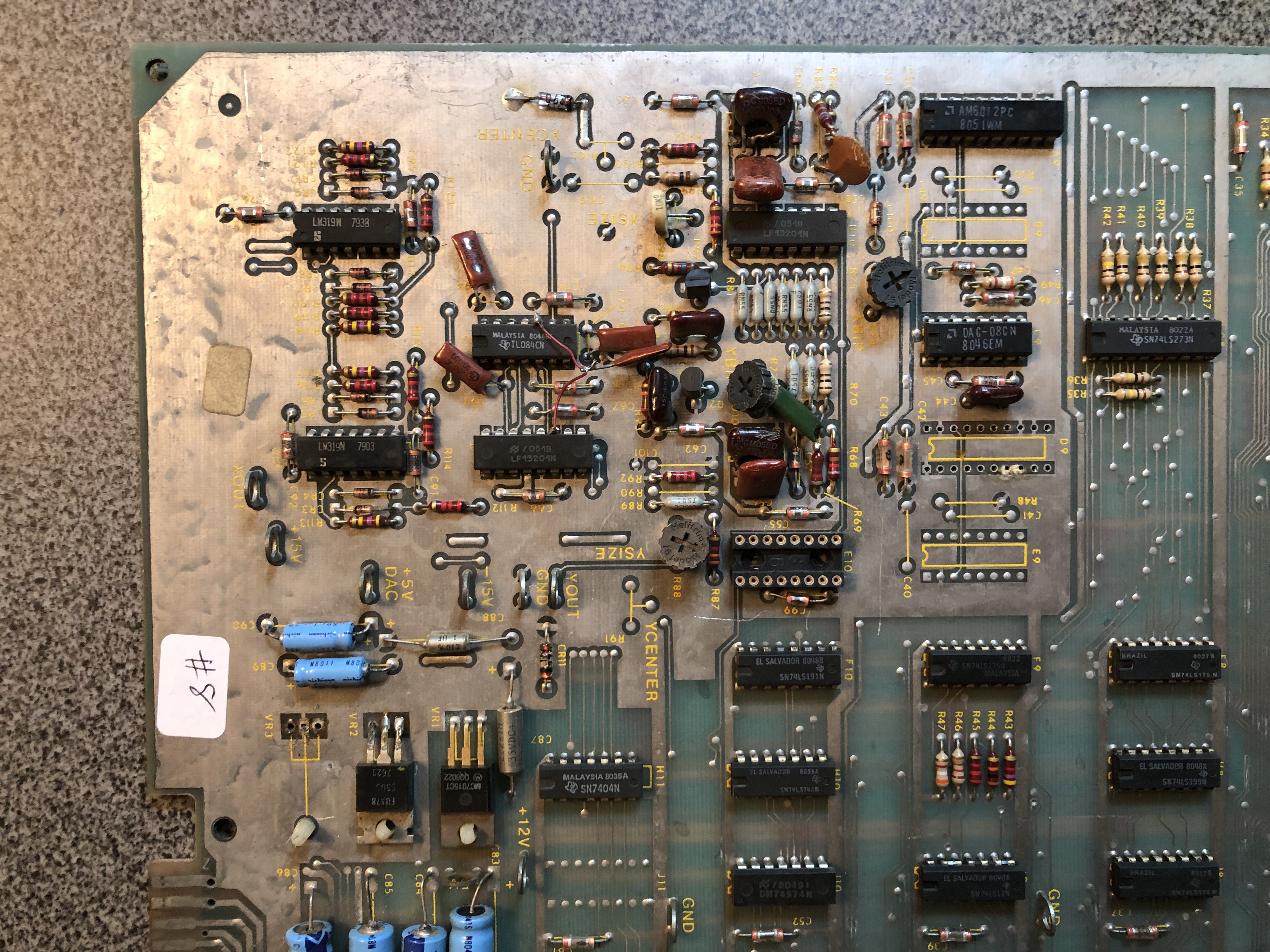
The analog section had a number of issues. R69 was just missing. Clipping to the TL082s made it look like they were both bad (at first).
I had socketed the TL082s, but no difference. Both LF13201’s at B10, E10 were bad corrupting the output of the TL082s (pin 7). Mixed in there the AM6012 DAC@D9 was also bad. Once that settled down..
I had Battlezone running for a while. I few hours later, TL082@A10 failed.. Everything shifted left. Good thing it was socketed.
Once I got through all of the burn in testing, I went to my final checklist. That list tests all of the inputs and outputs.
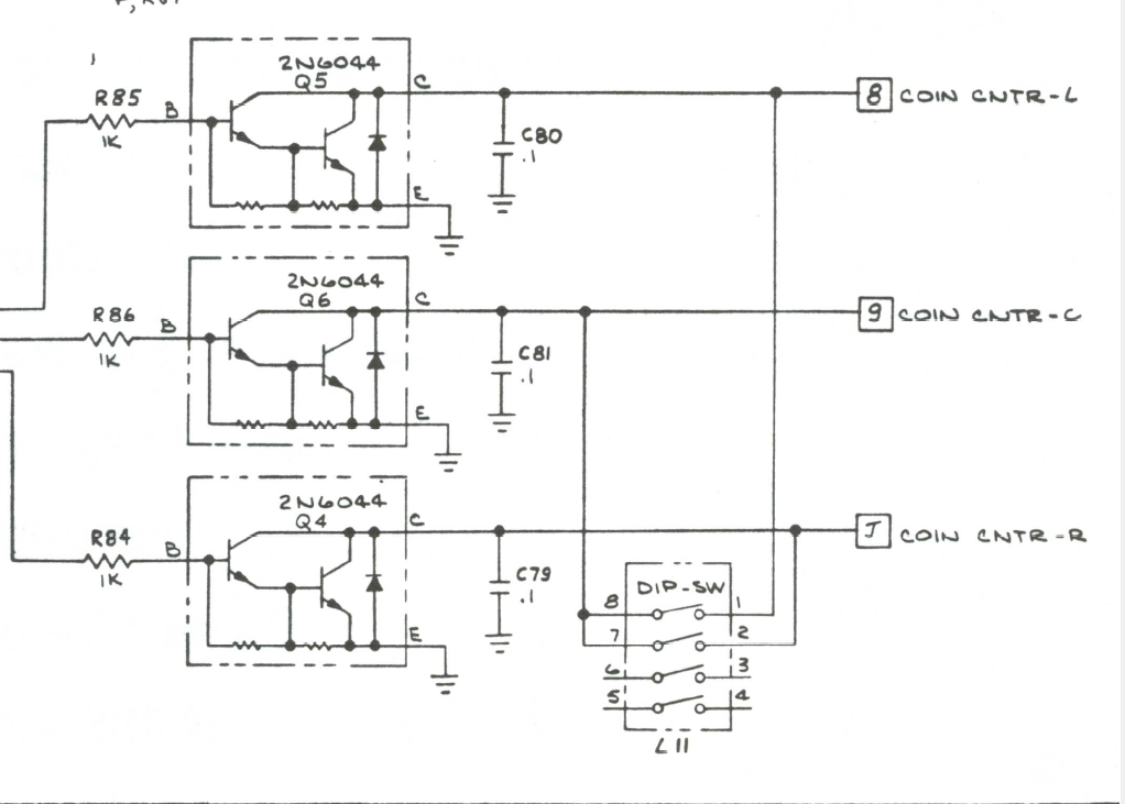
Adding a credit to the RIGHT coin slot caused the board to reset. Replaced 2N6044@Q4.
Atari originally designed in X/Y centering pots – but decided not to ship the boards with that feature. All the circuitry is there – I always replace the originals and add the centering pots (plus the caps and resistors they require) These are much more reliable.
The second AUX board, not to be outdone, was a bit temperamental – flexing would cause mathbox errors. Replaced socket@F2. It had no rumble sound, the resistor@R11 was missing. Added it in to restore the rumble. Lastly the Pokey mostly worked, but it chirped now and then. Testing showed a bad audio channel.. Replaced the Pokey. Aux board #2 works.
Boards work!
