
I’ve been hesitant to cut the control panel to shape until I received the overlay artwork. Now is the time to cut and test the shape. I received the preliminary artwork and printed it at Staples. Based on what I have – I can at least cut the outer shape so I’m not looking at a square CP blank on my cabinet.
Below you can see the underside of the CP and some 1/8″ hardboard. Since I’m using the router table – I just duplicated the entire panel by double stick tape, trim close and then using a pattern bit with a bearing – cut the template out.

I like using 1/8″ hardboard because it is very easy to create fair curves. You can get very picky about the shapes w/o ruining expensive plywood. One of the reasons for all the extra work is because of the curved face to the control panel box. There are two curved lines. The inner one follows the face of the box, the one at the edge is for a 1″ overhang. Drawing that line is simple – find a 1″ block of wood and slide it along the face of the CP box with a pencil.
Here are a few steps shown at the same time.
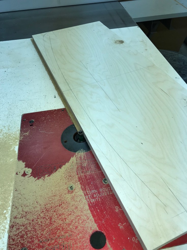
First I lined up the template stock and taped it in place – it’s set back the depth of the curve. Using a compass I made a bunch of semi-circles along the length of the curve I’m trying to duplicate. Next I use a flexible strip of wood and connect all of the tops of the semi-circles. Use as few weights to hold the curve as you can so you do not end up with lumps. The wood strip will make a nice fair curve if you let it. Then draw the line to cut too…

Here is a better view of it. This is the second try actually – I didn’t like my first attempt. (as seen opposite of the side I’m working on) The shaping is a bit finicky if you are working toward a fair curve. My artwork will have some boarder lines that will follow this curve. The lines were drawn from my Sketchup drawings. I’m really just trying to make the CP as close to my plans as I can so that everything looks right. Shaping this curve should match the line on the underside of the CP. My goal is to try to split the pencil line drawn on the bottom of the CP.

My next step is to take my curve template and create a single pattern for the final CP. The arrows show the two curved parts that are the shape I wanted. Everything else is waste. I use the tablesaw fence to keep things squared up and I have a piece of 1/4″ hardboard (scrap in my case) to copy the curves too for the final template.
To get the final shape – I double stick taped the curve template in position, trim then finish at the router table. Then I flipped it over and did the opposite side so I perfectly mirror the shape left to right. The I re-positioned to get the opposite corners and flipped again to mirror. Basically I flipped and moved the pattern 4 times to get all of the shapes duplicated to the 1/4″ hardboard. My original plan was to make this one the template all at once. But it turned into a pain.. Much easier to just make the curves you want and reuse them on another piece of material to get the final as shape.

My hardboard template is completed and double stick taped onto the actual CP. My pencil lines on the back match perfect.

Quick pre-trim with a bandsaw and then finish with the router table. Another reason to use a pattern and a router trim bit at the table is you get perfectly square edges for the T-Molding. No gaps or weird shapes to contend with.

The best part is down the road if I decide to change the CP – I can make a new blank in about 10 minutes with this template. The leading edge mirrors the curve of the CP box and the artwork for the CP matches the shape.
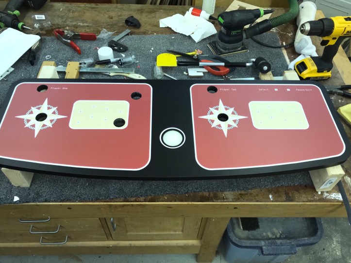
Here is a preview of the marquee.. I had the CP and marquee printed up at Staples. Both need some minor changes. Here the font is just a bit too big – so it needs to be shrunken a bit.
More importantly – the CP is now the right shape. I’m going to wait for the final overlay to be completed before drilling holes for the trackball & buttons.

My overlay has a design that needs to be aligned to the control panel so that its border lines are spaced evenly all the way around. (Will be shown later).. All of that is dependent on the trackball being positioned at the correct spot. I spent some time checking the artwork against the CP blank to be sure it all lines up so that the center of the trackball is positioned in the artwork properly. Lots of checking and cross checking – then I’d wait and check a different way later.. just to force myself not to rush. Hopefully that prevents expensive mistakes.
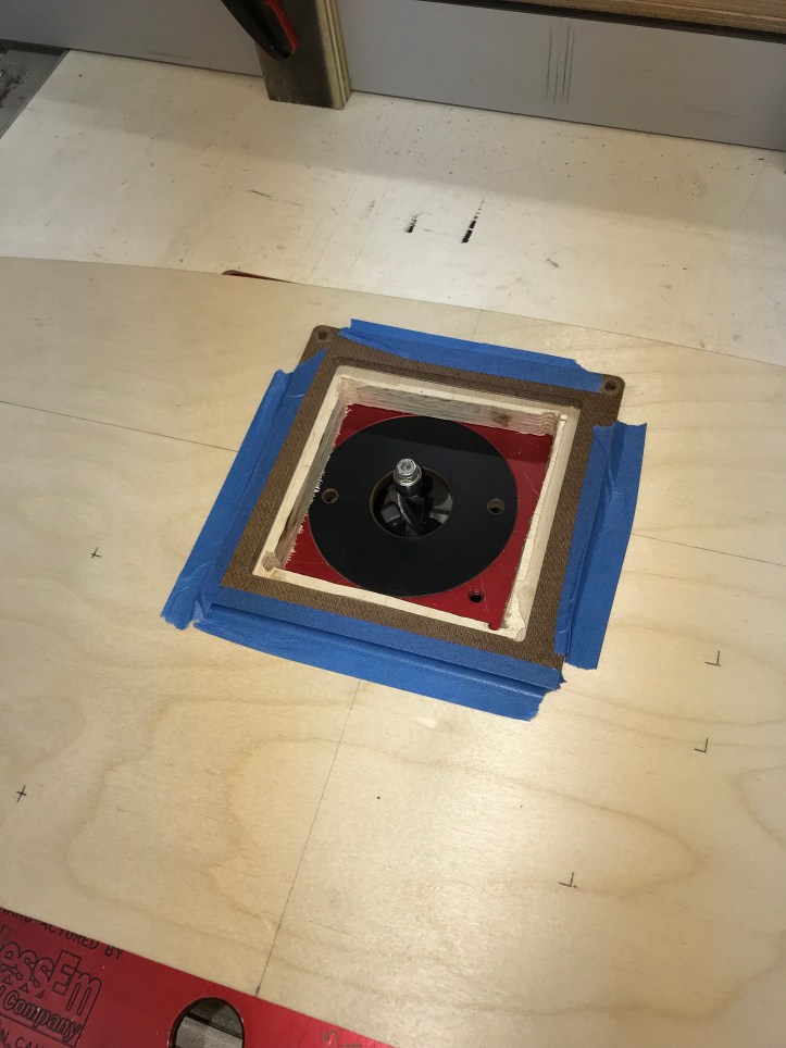
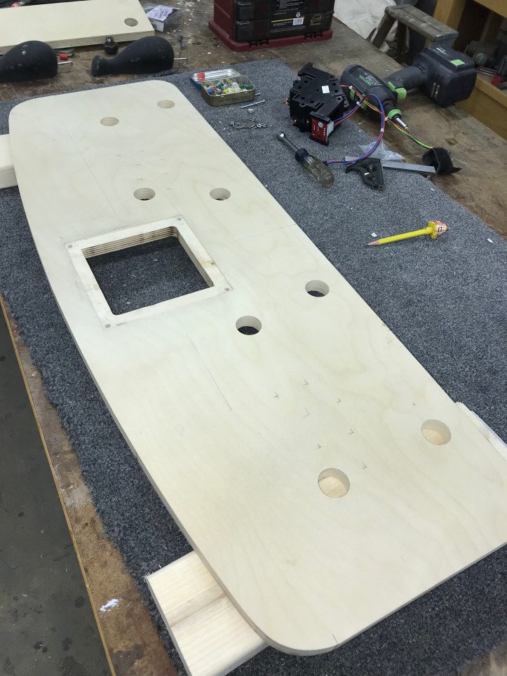
Step 1 was making a template for the trackball mounting plate. My plan is to recess it into the control panel and sand it all smooth and cover it with the artwork. Hopefully none of it will imprint/show through the overlay – that’s the plan anyway..
Creating templates using an Inlay router bit set is pretty well documented. The way I did it was I created a 12 x 12 blank from 1/4″ hardboard and created a cross pattern and a center point on it. Next I bolted the Trackball mounting plate from Twisted Quarter to the hardboard. You can see the ‘X’ and ‘+’ pattern that got the plate centered here after I cut the template.

Using the router & inlay kit (without the bushing attached) I copied the shape of the mounting plate to the hardboard resulting in the picture above. The large outer template is the now the right size to route the recess in the control panel when using the added bushing.
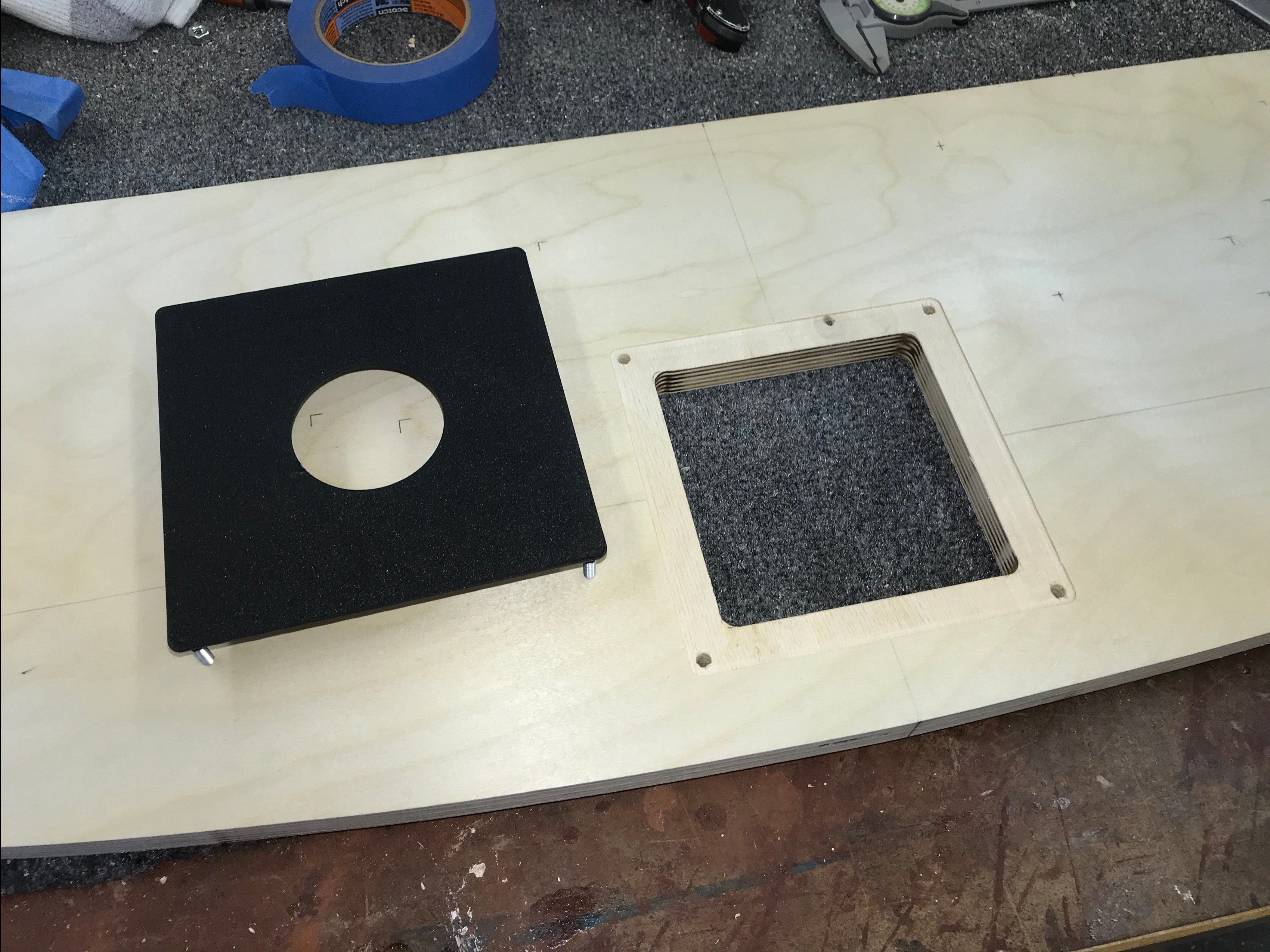
The inner template is larger that the mounting plate because of the router bushing. I used a pattern bit on the router table to duplicate the shape of the plate exactly onto this piece. The reason for this is more about neatness (for you OCD freaks!) than anything else..

To create the opening for the actual trackball – you could cut it out – cover it with the plate and be done with it.. I expect I’ll be opening the CP a lot to show people the innards. So for me neatness counts. I’m using the small piece to make a pattern to cut the inner opening.
Using the router table/fence/stop blocks – I cut the template to a 5/8″ width all the way around. It made for a snug fit for the trackball. You also get drill guide holes for the mounting plate as a positive side effect.

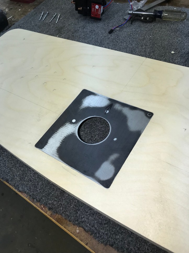
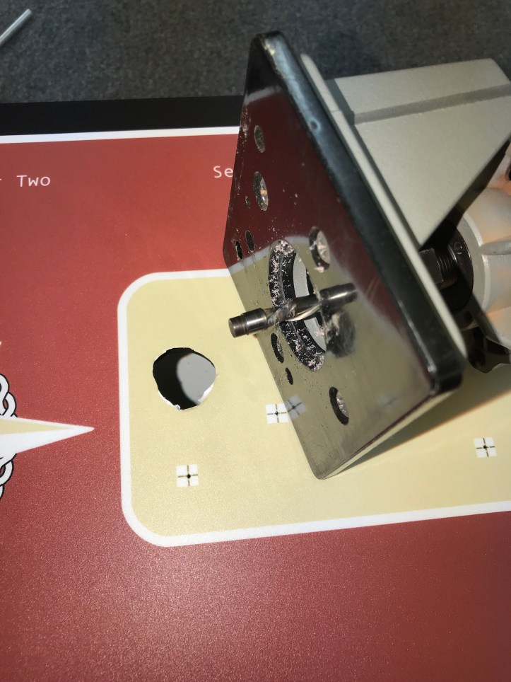
Back to the mounting plate recess. I double stick taped the template to the CP and used the inlay bit to route the perimeter of the recess.

With that done – I removed the template and flattened out the inside portion of the recessed area. You can see some test cuts in the center waste to make sure I got the depth right before routing the edges.

Now the easy part. Cut out the center waste area and mount the inner template.. It should fit perfectly as a match to the mounting plate.

Then clean it up with a pattern bit.
Finally – drop the mounting plate in.

My mounting plate required a little fitting and adjusting. Getting the shape of the recess is relatively simple with the template method above. Getting the depth of the recess to cooperate is a little trickier. Mine was about a sheet of paper not deep enough. If you are not sure – then better to make it 2 sheets too deep and shim it from behind than try to remove more material once the template is removed. Making the depth a little deeper requires a fair amount of hand work with the router and chisels.
My CP will have the plate covered. Another thing I should have done first is sand the plate smooth. You can see the studs had dimples on the surface. Sand the backside that makes contact smooth too. Overall this plate was made to very high tolerances – I’m quite happy with it.. Had I sanded it first – my first pass at the recess would have been a bit closer. All that said – you will still feel the slightest transition from the wood to the plate. So I’ll be skimming in some filler to ease that and hopefully prevent any imprinting from behind.
My cabinet has a bit of a theme – Lakeside Arcade. The CP specifically draws from my largest project to date – The Miss Sheri Lynn. Colors and some design thoughts are from the boat. I also didn’t want the CP to be overly busy. Final location for the entire machine is at the lake house.
My layout has the trackball centered in the white circle. The white boarder carries over from the deck design of the 40’s runabouts. Keeping the spacing right has been top of mind.. But I think I have it figured out.
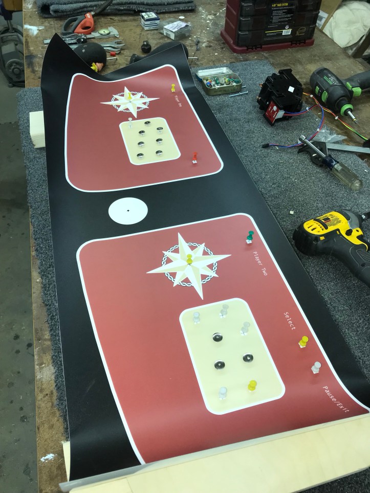
I used thumbtacks to pin the overlay in place before the trackball mount was routed out. More tacks = less ability for the overlay to change position. Every drill point is marked by the thumbtack hole and I can reset the overlay to the exact position.
Next step – I drilled four holes on each side. They are the furthest apart on either side of the CP.

Next I pinned the overlay down using all of the thumbtack holes so that it was back in its EXACT location. While there, I carefully cut the six openings on the left and used buttons as clamps to hold the overlay in place. All six of them together are doing the same work as the tacks – allowing me to position the overlay is the exact same location repeatably. When the time comes – I can stick the overlay down from right to left – removing my buttons/clamps as I go.. No shifting!

Remainder of the holes drilled. Next a skim of filler, sealer coat and some paint for the edges and bottom. If all goes well it will be a wiring weekend

I skimmed on some bondo around the trackball plate. Just a few slight variances as expected. Also added a coat of sealer to fill the grain.

Next I painted the panel black – and discovered that the studs that hold the mounting plate hit the Control Panel box when it closes… ooops…
So I popped the mounting plate out, counter sunk the holes, cut the studs and put it back.

which of course meant I had to reskim the joint with Bondo.. Very little time lost on the redo however. No need to repaint – its getting the overlay.

Even with my button hole alignment system – I still wanted to check that the alignment of the boarder line was even with the top edge of my panel. Here is my handy CP overlay alignment gauge (patent pending).. Check along the length of the overlay. I got that last little fidgety check in to keep the line even. Using the buttons as clamps worked well here.
After that – I stuck the CP overlay down from right to left. Trimmed the edges and trackball opening.

This is what I was going for (for some reason.. don’t know why) I wanted a white ring around the ball. I got it to within the width of a pin of variance. I’ll take it.
Trimming the remaining holes with an Exacto knife was going slow and sloppy.. My trim router and a spiral bit with bearing did the job. Cut a rough opening and clean up with the router. If you have the tools – this is simple and clean. I cleaned the bit with acetone after every couple of holes. The adhesive gummed it up a bit.
No doubt this CP design is not for everyone – its not very ‘arcade like’. It will fit in at the lake house and it is uncluttered – which I like.
All my buttons and controls in place.
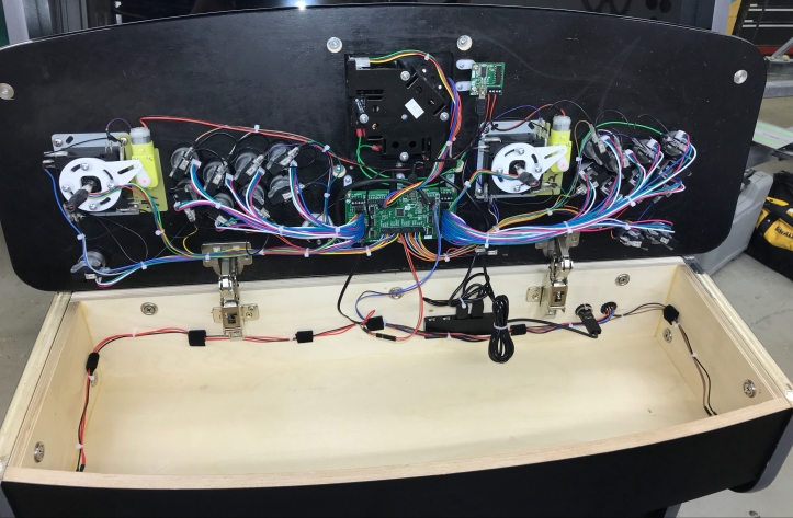
Did a check to make sure the CP will fit with everything installed.. Good thing – I had to reposition the IO card so that the power and USB connector wouldn’t jam up on the back of the box.

Got through connecting all of the ground wires and continuity testing.. Went better than expected.. Everything worked on the first try.
Next I made a cheat note so that I wouldn’t get confused on the button wiring. Which was writing down the layout and flipping it..

Here I got started wiring –
After this –
Got all the buttons wired up – cut each to length and re-terminated them… and then realized I should have mirrored the numbers, not flipped them..
grrrrrrr.. re-wired 8 buttons – rookie mistake..
Here are the tools I’ve been (mostly) using for the wiring. Cutters, two types of wire strippers, crimping tool, small torch for heat shrink tubing and most important – tester for continuity. I made a building stand for the CP so I could flip it, wire, etc.. w/o having it all bouncing around on the bench. It is a piece of scrap particle board from a prior project, two scrap 2×4’s carpeted to support the CP making room for the joysticks and buttons.

Everything pretty much comes back to the Ultimate I/O card. Using the continuity tester is simple. Set it to beep when a completed circuit is detected. Clip one lead to your negative terminal and then push a button while checking its connection on the connector at the card. There is just enough exposed to do this.. Getting all of them tested now is worth the effort. You will likely have a bad crimp or connection someplace. Find them as you make them.

For some reason I want to make sure the CP is modular enough to take apart. I *could* make interchangeable panels the way I have this all set up.. Pop one off and put a new one on in short order.. That said – I used connectors on the CP box for the USB and the 7 wires I need to get in/out of the CP. The connector has really small solder points.. My crappy 25 year old Radio Shack soldering iron is not the right one for this.. but I think I have good connections inside the box.

My coin door will work with quarters – maybe someday I’ll find tokens and adjust to them. The coin ‘buttons’ are on the bottom of the CP box. One on each side. The plan is to make them ‘switchable’ in the event I need to disable children from going crazy 😛

Coin button inside the CP Box.

Here is where I am at this point.. Sticks and buttons all wired up and tested. I even connected the Servostick USB board to my laptop and changed the sticks from 4 way to 8 way about 10 times for fun.

There are a few more wires to connect and some cable management tasks left inside. Final big step – making the connector from the cabinet to the CP box.

I picked this up at the electronics store. Does exactly what I wanted. Connects a bunch of wires to the CP box so that I can keep it modular.
Early on I decided I wanted RGB LED buttons. Paradise Arcade sells a very nice button with an easy to set up LED.. The cable is GENEROUS at 40″ long! The vast majority of them I only needed to be 6″-8″ long. I chose to cut all of them to proper length and re-terminate them with their 4 pin Dupont connectors. Wiring isn’t for everyone – but this may have been my favorite part of the project. With mistakes and re-do’s – I did over 100 little Dupont pins.
Testing each wire and configuring each LED one at a time was very satisfying.

I popped the CP off the box and zip tied and velcro’ed the harness in place for the coin buttons and the connector coming in the back of the panel.

Everything all wired up and tested.

Same thing – harness all zip tied into position.

Back in place. It looks pretty official to me. I suspect I’ll be giving a few tours of the inside of the CP, the coin door and inside the cabinet.
Construction completed.
I have a few wires to tidy up inside the cabinet and then install the rear panels. I tried to get a decent pic of it in the shop – but its not possible with the lighting and all the other stuff in there.. I’ll get some nicer ones once I move it.
My software on the other hand is still a mess… I have considerable work to do to make the machine ‘consumer ready’.

[…] Lakeside Arcade: Making the Control Panel […]
Sir thank you for Sharing this. Would I be out of line as to ask you to share your schematics or sketch up documents , I’d reallu love to build this for myself but I lack “eye” to do this without a template.
Sorry for the multiple post. Instructions For your cabinet & control panel specs (your build) I’d really love to replicate this & will credit where it’s due! With you
https://bperkins.wordpress.com/2017/11/18/arcade-machine/
Hi Ali – thanks 😉 Here is a link to the Sketchup plans.. I do not have a schematic for wiring.. There are many ways to wire and get the same result. Let me know if you make a cabinet.
Thank you!!! So very much. Did you ever update it with a cultist to get both panels off one sheet? I’m still in the early planning stages . My main concern was finding a cabinet that will work. I believe you have achieved that one. I’m still debating which front end, LEDs or not. Digital marquee etc. but your blog and expertise are making this more of a doable project!
Hi Ali,
I never went back to make a cut list. The important thing to know is you can get both sides from a single sheet of plywood. After making the first one – the second one is easy.
Good luck!