
I was very fortunate to pick up a Star Wars locally for a great price. It was reported as ‘it worked sometimes’ from the owner. He had it for nearly 20 years and his kids were not interested. He wasn’t a collector and decided it was time for it to move on.. I was lucky and beat over 20 people who wanted it. Original Amplifone monitor and all matching serial numbers. Cab is in A-/B+ condition.

My machine had an issue where during the battle with the Tie Fighters, the screen would glitch to a lighting bolt.. then go blank .. then continue. No game reset and only while the screen was full of fighters.
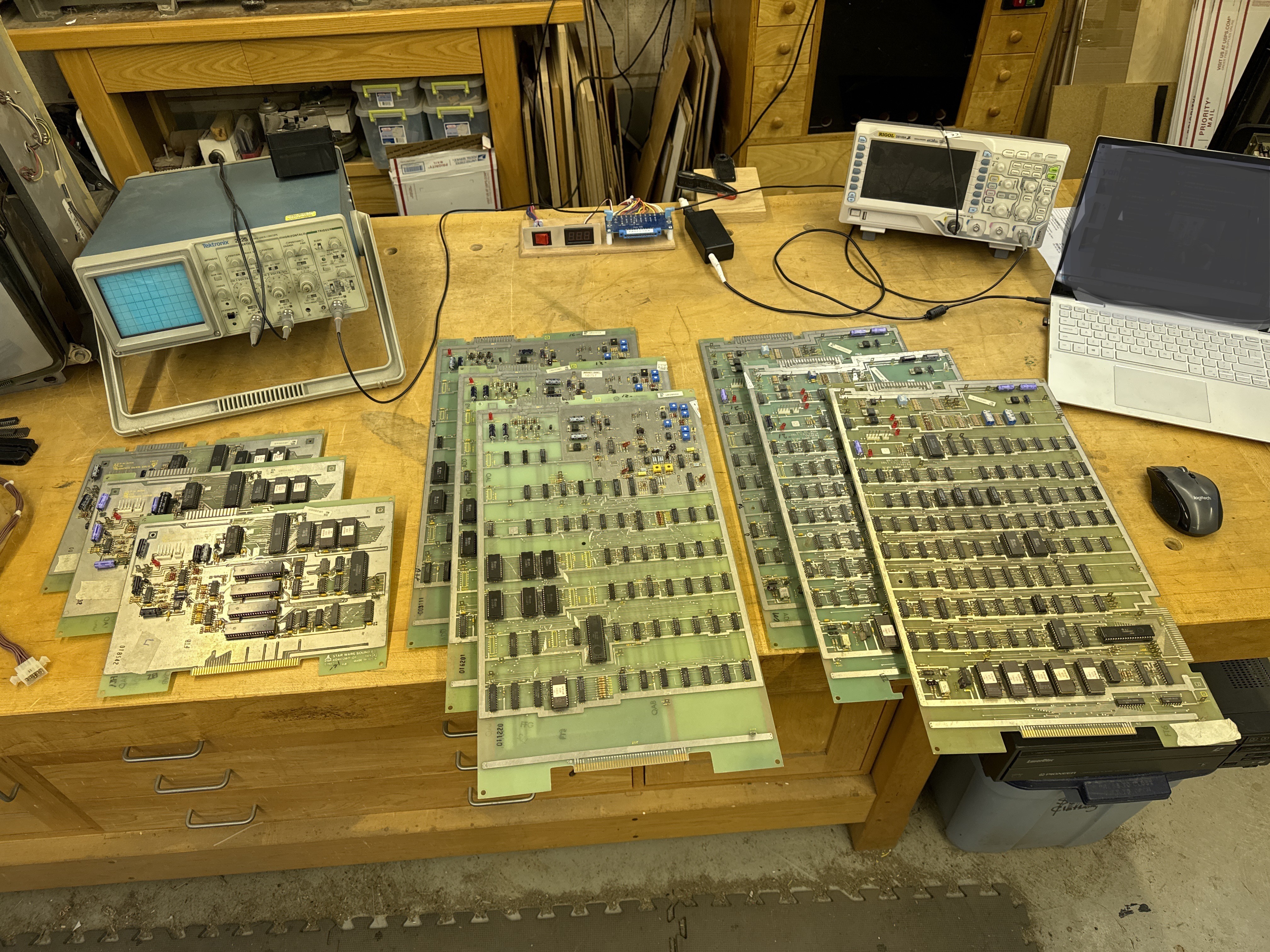
My plan was to add Star Wars to my repair list.. but working on a 3 board stack was going to be a real pain. Building another vector brick to PCB full harness was also going to be a significant amount of work. All of this brought me to revising my bench repair approach.
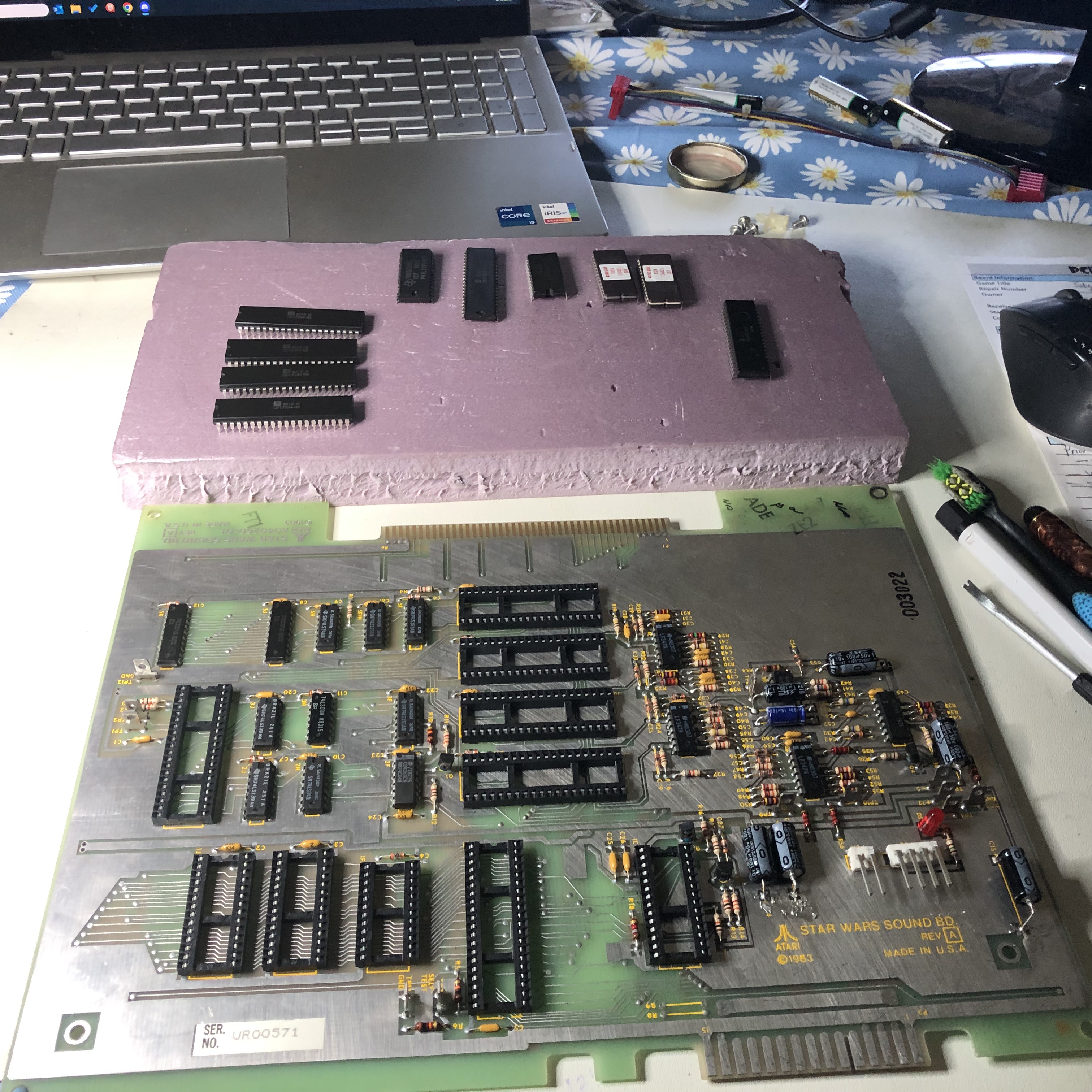
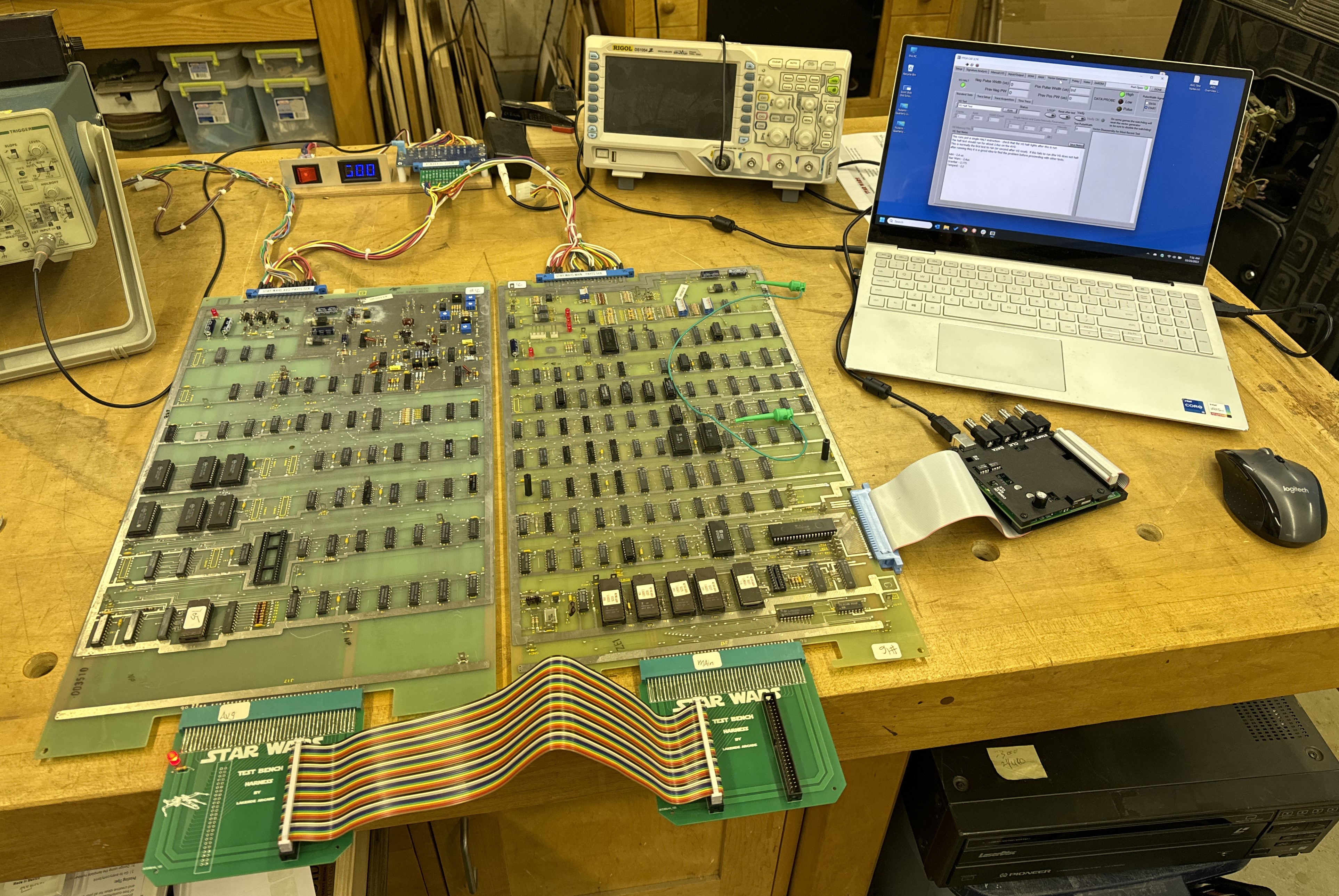
Atari Bench Test Rig – I created this to make working on Atari board sets simpler, being curled up behind cabinets is not the best way to do repairs. My first couple of bench harnesses were much too complex. It’s BEST feature is I can swap out boards on the bench in in seconds without resetting power connections and rechecking power to make sure voltages are correct.
On the far side is my card edge adapter (not completed – power only at this point – monitor and controls came later). That goes to the ARII and is part of my test rig.

On the near side – I created an interconnect adapter specifically for Star Wars board sets. The PCB’s are designed in such a way that all are identical. The connection to the ribbon cable determines which board each adapter gets connected too.. Unfortunately – it is a bit unreliable. Some board sets work, others do not.. My guess is the TTL drivers are unable to get clean signals across the boards and ribbon cables at length. I can still use the connector and do testing – but in the end I have to put on the actual backplane connector.
It was a fun project – but I’m not an electrical engineer and do not understand circuit design enough to see if there is a way to make this work in the log run.
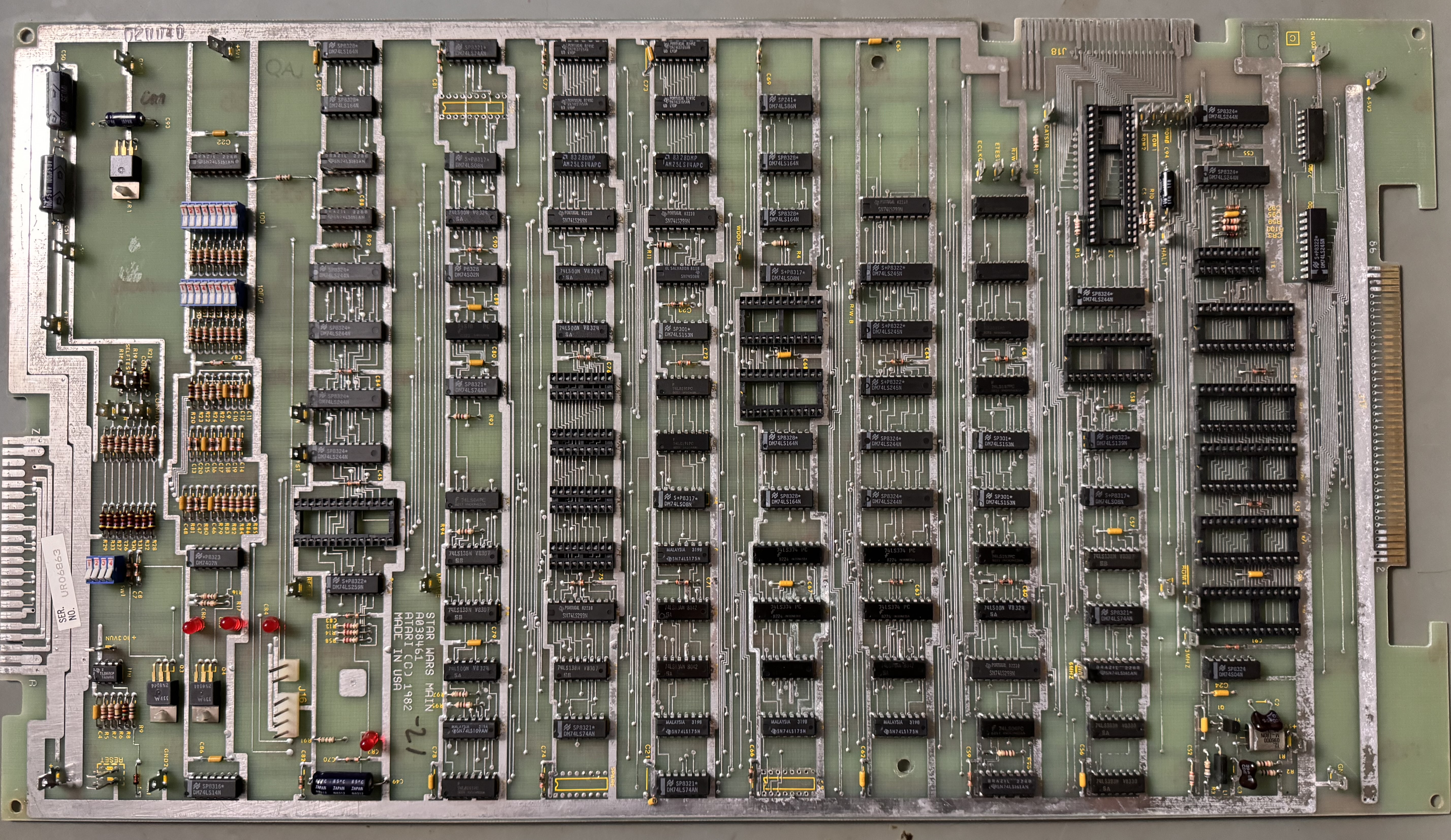
Board #1 – My Star Wars Board
Used the FPGA CATBOX and tested the AVG Chip. It had an interesting failure in that it could address all of the vector RAM – but the timings coming off from the HALT signal were off. My game would have the vectors fail – usually a thick red lightning bolt shape – when the screen got very busy with activity. It would pick up right where it left off once the game produced less vector generator commands..
Replaced AVG Chip – Board Works!
Board #2 – Board in for repair
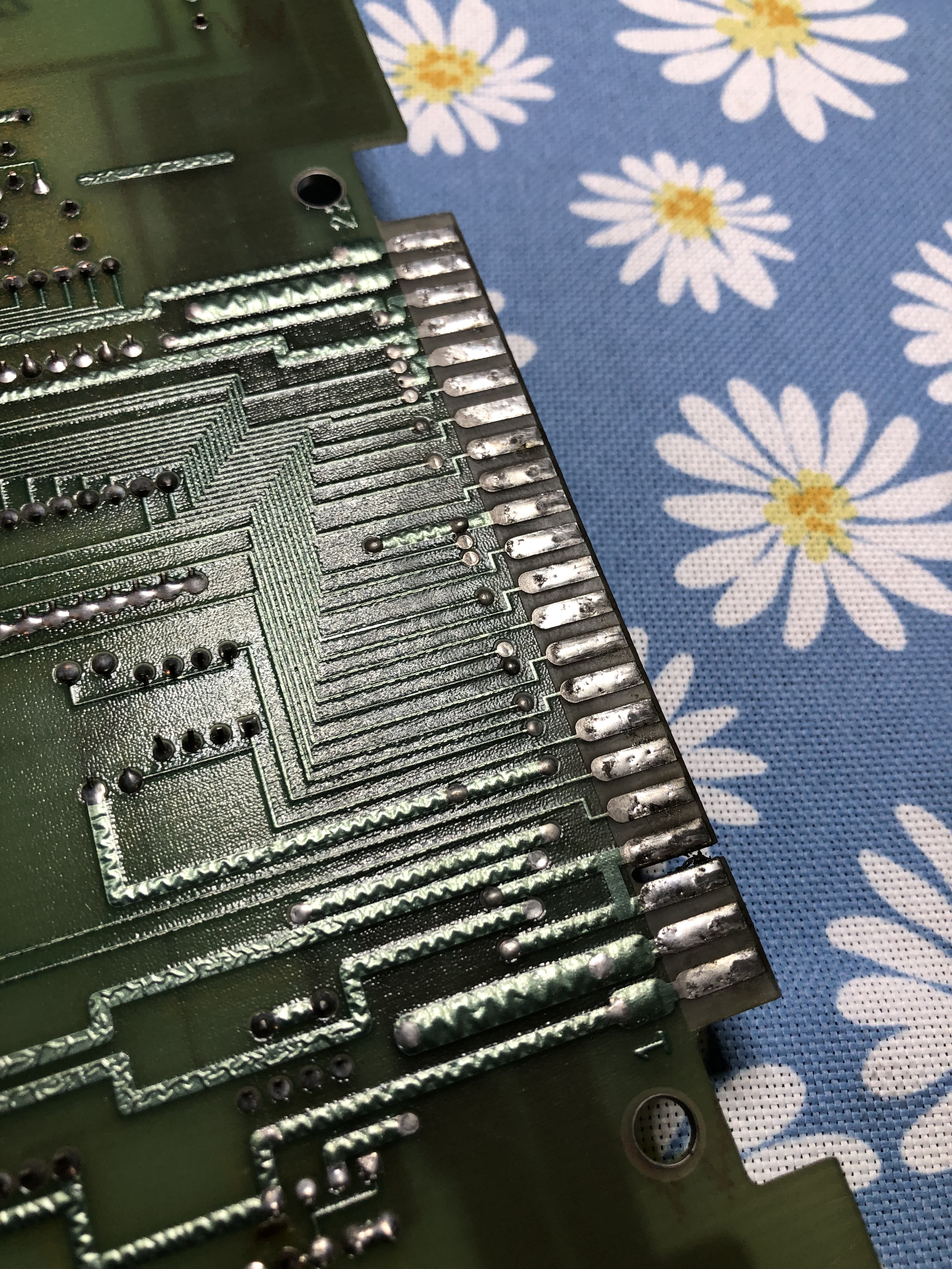
Board was sent in after someone tried to replace the sockets and shredded the traces.
Missing the X2212 EAROM for high score saves.

Look close there are missing and buckled traces across the 3 sockets. They removed the shredding.. But the damage is done.


I’ve come up with a method I like to repair damaged traces on the parts side. Jumper wires on the back would be much faster – but subject to snagging and damage. Here are a number of the bad traces with Kynar wires bent down through the via’s and tacked to the topside trace with solder. It can take a few hours to work all through these. If you are not sure. Add a wire. If for some reason you need to remove the socket after the fact – there is a good chance you are doing the entire socket rewire again.. Once all the wires are in – I clean the flux with alcohol and use a clear UV curing resin to lock the wires in place. The heat of soldering in a socket will cause them to break loose without the resin to hold them.

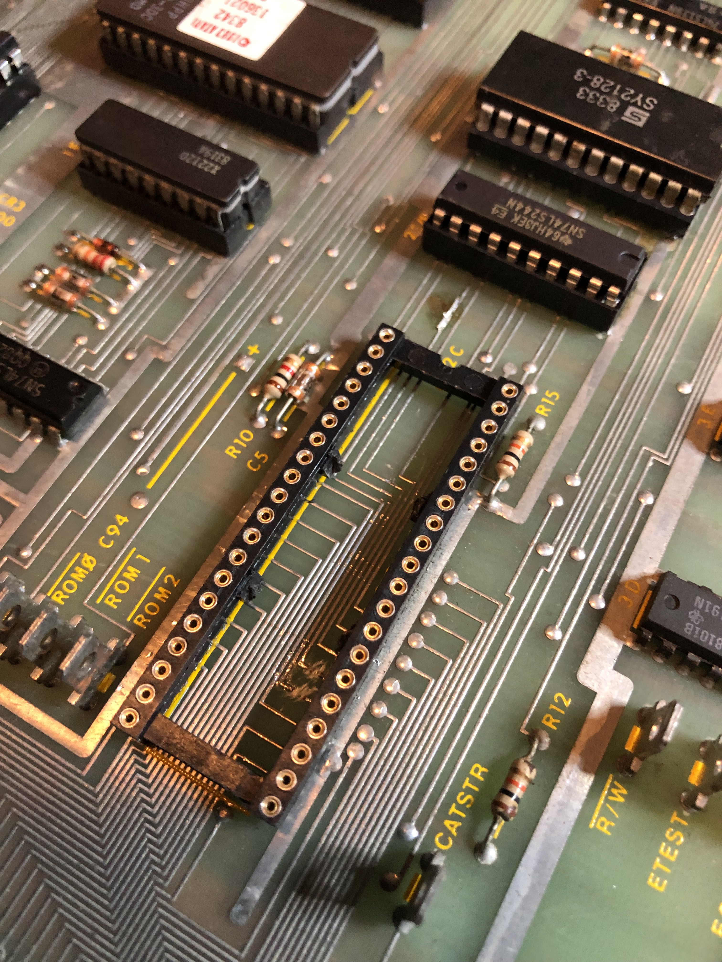
This socket at ROM4 had been replaced with broken traces under it..?? On the right are repaired traces with Kynar wire and resin in place. The toothpick is holding the wire down because it was so long.. it was popping up. Right after this I used the UV lamp to cure the resin and lock these wires in place.


New sockets on the first 3 repair sites. Completed repairs on the right. You will have to look hard to see work was done.
Boardset got all a full chip cleaning.
Board works!
Board #3 – Board in for repair
Board sent in with Mathbox errors
Did a full chipset cleaning and inspection.

Looking at the description – you would think this error was on the AVG board. Working through the schematics – the divider is on the main PCB. Because there were so many – it seemed like it would be a chip that would have multiple inputs.

LS374@5L had failed. Replacing cleared all the Divisor errors.
Once the game was up and running – All tests worked except the yoke. How am I supposed to fly an X-Wing without steering?
Replacing the analog to digital converter @9K repaired the yoke.
Board works!
**** Revised ****
Board came back unfortunately –
My guess is this cabinet has bad power or maybe is not grounded? I know ground pins got cut off the cords all the time.. These are odd failures considering the 4 day burn in time from before.
The LS244@1P on the AVG board. It was pretty tricky to find.. the HALT pin was internally shorted to GND .. Which was messing up the VG. The game ran, but the vectors were messed up at times.
Second – The sound was messed up. All 4 channels were playing at the same time… ROM 208 on the sound board was bad (Tests good on a tester, but the game didn’t like it) – replaced it.
Finally the X2212 NVRAM was bad – was ok before.
Ran the board through another 4 days of testing and will let the owner know they should check their power supply.
Board #4 – Board in for repair
After cleaning, testing and working through it..
AVG chip is bad
Vector ROM #105 is bad
Sounds were messed up – took a while – narrowed that down to a partially failing LS374@5J on the sound board.
x2212 NVRAM is bad
Replaced all offending components.
Board works!
Board #5 – Board in for repair
Board reported to have some issues.
- Came in with Vector Labs ESB kit – removed for testing
- Removed all chips, cleaned legs, Deoxit
- Installed EPROMs, PROMs, etc. for standard Star Wars configuration
No issues..?? Maybe flaky power..
Reinstalled ESB kit – Testing for 4 days as usual.
Board works!
Board #6 – Board in for repair

All 3 boards were pretty clean to start – very little prior work.
Performed standard maintenance:
- Removed all the chips
- Washed & inspected the boards
- Cleaned all legs, DeoxIT

After testing RAM, ROM, etc. Connected to scope and then monitor – errors.. Ended up chasing this one for a long time.. Seemed like it all should have been working.
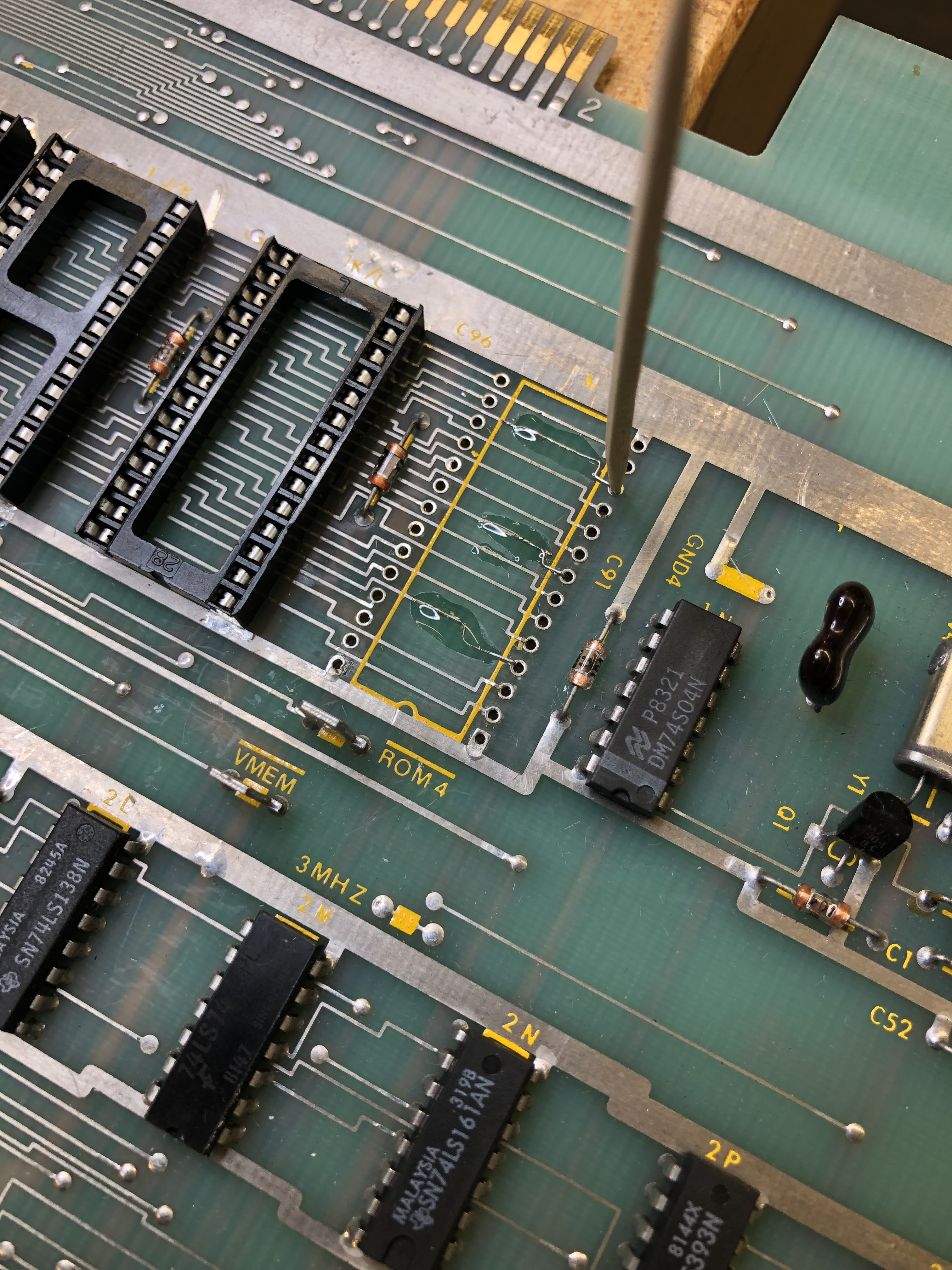
Finally I focused in on the clock going into the matrix processor.

Pin2@9D – here on the scope it is overshooting pretty significantly.
More research took me to this note: Atari internal memo collection. You can read through it – the important part was:
On the boards that I received, the problem with the RAMs at 5F and 5H
were all solved by connecting a 180 Ohm 1/4 Watt 5% carbon film resistor
from 9D pin 2 to ground. There is a convenient trace on the top of the
board to attach it to.
I tried this and it worked perfectly.

I did spend some time trying to figure out how if a chip was causing this, replaced the 74S04@1N – but that did not solve the issue.
Board works!
Board #7 – Board in for repair
Initial Inspection:
- Stack has had lots and lots of prior work
- Note: None of the prior work caused any of the issues once I was done.
- Not sure if parts were shot gunned or if this stack has just had a very hard life.
- CPU Board
- Missing CPU
- Many socketed chips
- Lots of prior work
- Edge connector solder blobbed
- Jumpers on the back
- Cut traces under CPU
- AVG board
- Original AVG chip
- Edge connector solder blobbed
- Sound board
- Missing CPU
- Prior work
- Been recapped

First thing I did was remove the white jumpers on the back and repaired the traces under the CPU socket. That cleared up a RAM error missing bit5.


The two main issues (so far) are BAD MATHBOX READY LINE and the ‘partially’ corrupt graphics.
The original AVG chip was bad – replaced it.. After that, AVG board was the source of the corrupt graphics. I had inspected it pretty closely and spent a fair amount of time trying to determine the cause.. In the end.. I had plain old missed this:


The cut trace was OP1 – which makes perfect sense it was partially corrupting vectors in the vector timer circuit. I had looked there a number of times.
CPU Board – BAD MATHBOX READY LINE

Machine pin sockets all over this board. All were good as it turns out. Just having this much prior work to verify took time as I was poking through it all.
This may be the least documented issue with Star Wars stacks. More often than not (it seems) replacing the PROMs will fix the problem. Not in my case. The CPU board had a bunch of issues. All of them I corrected while trying to find the source of BAD MATHBOX READY LINE (BMRL)
While hunting for BMRL – I was able to trigger a divisor error:

This points to self test #21,23,24. All divisor tests as expected. LS374@5L (the only one not already replaced) was the issue.
I chased a few ghosts looking to the BMRL and have a better understanding of it now.

After considerable checking, testing and comparing to a known good CPU board – BMRL is a result of failed processing from the PROM@7J and specifically IP8, IP9 and IP10. Once I came up with that – I found the root cause(s).


Here is 12MHz feeding into LS00@8D before and after. The clock signal is not pulling back to zero. Removing and chip testing revealed a bad chip.. Could it be that?! No.. didn’t fix it.

I’m certain I had previously checked the LS161@9D with my logic comparitor – and got no results. But I may have corrected something along the way. I piggybacked a new one and lifted pin12 and compared signals.. The LS161 on the board was outputting clean square waves and the piggyback one was just signaling high.. The comparitor now lit up all the output pins. Replacing the LS161@9D fixed BMRL!! Finding chips with dead pins is way easier than finding ones that are just putting out bad results.
Somewhere along the way I also found a bad LS08 and another LS00.. Which fixed something I would have seen after the BMRL was cured.
Sound Board:

Pretty clean looking board – missing the CPU. Once I focused on it for a while it had the following issues. 3 bad pokeys (ouch) and the sounds were very faint – but I could get it to generate all of them. If I removed the TL084@3C I would get normal volume.. really? It was not the problem.

The R5106 is the issue – it is an audio chip (Reticon R5106) that adds some reverb to the sounds. This one is bad. If you jump pin 6 <-> 4 – sound is back. Unfortunately they are hard to come by – you can get one for $30+ it seems. The sound is a little flat without it..
Board works!
Board #8 – Board in for repair
Initial Inspection:
- Stack has had lots of prior work
- Missing sound cable
- Missing PCB interconnect
- CPU Board
- Surface rust on some CPU legs
- Almost no prior work
- AVG board
- Original AVG chip
- No prior work – just old looking
- Sound board
- All of the test points have solder blobs?
- Voice chip disintegrated upon removal
After initial maintenance – tested with FPGA Catbox – Only one RAM was working on the CPU board and the entire AVG board was not accessible. I found that EVMEM was not getting triggered correctly and preventing communication to the AVG board. The next part took a while to hunt down…

This is VERY zoomed in.. I couldn’t see this with my magnifier during initial inspection – A quick polish with the fiberglass pen and I could get to the AVG board. A Leakseeker for shorts is starting to look attractive.
Once the AVG board fired up – it had at least 4 bad RAM and a dead AVG chip. After replacing all of them..
The main CPU board was running better but I could not see RAM 5F5H – matrix processor address MA7 was dead @3H. Replacing the LS157@3H restored memory access to 5F5H.
Now I could get the board into test – and actually got the game up and running. Ran for about a minute – then the monitor went into shutdown.. Connected to the scope – no usable video. Probed around and determined the DAC@6A/B had died. Replaced.
Board is running – but it resets periodically. I’m going to leave it on for a day or two and see if I can finish off whatever chip is failing. I’m going to guess it is RAM since this stack already had 4 bad ones.
After letting it run another RAM failed – reset problem found. Board ran another day while debugging sound and the TL082@8B/C died.. Replaced it and overall the Main and AVG boards have been pretty solid
Sound Board:
The sound board put up a pretty good fight. I chased the right problem for the wrong reasons for a bit.. But this one had a lot going on.. The voice chip disintegrated upon removal too..

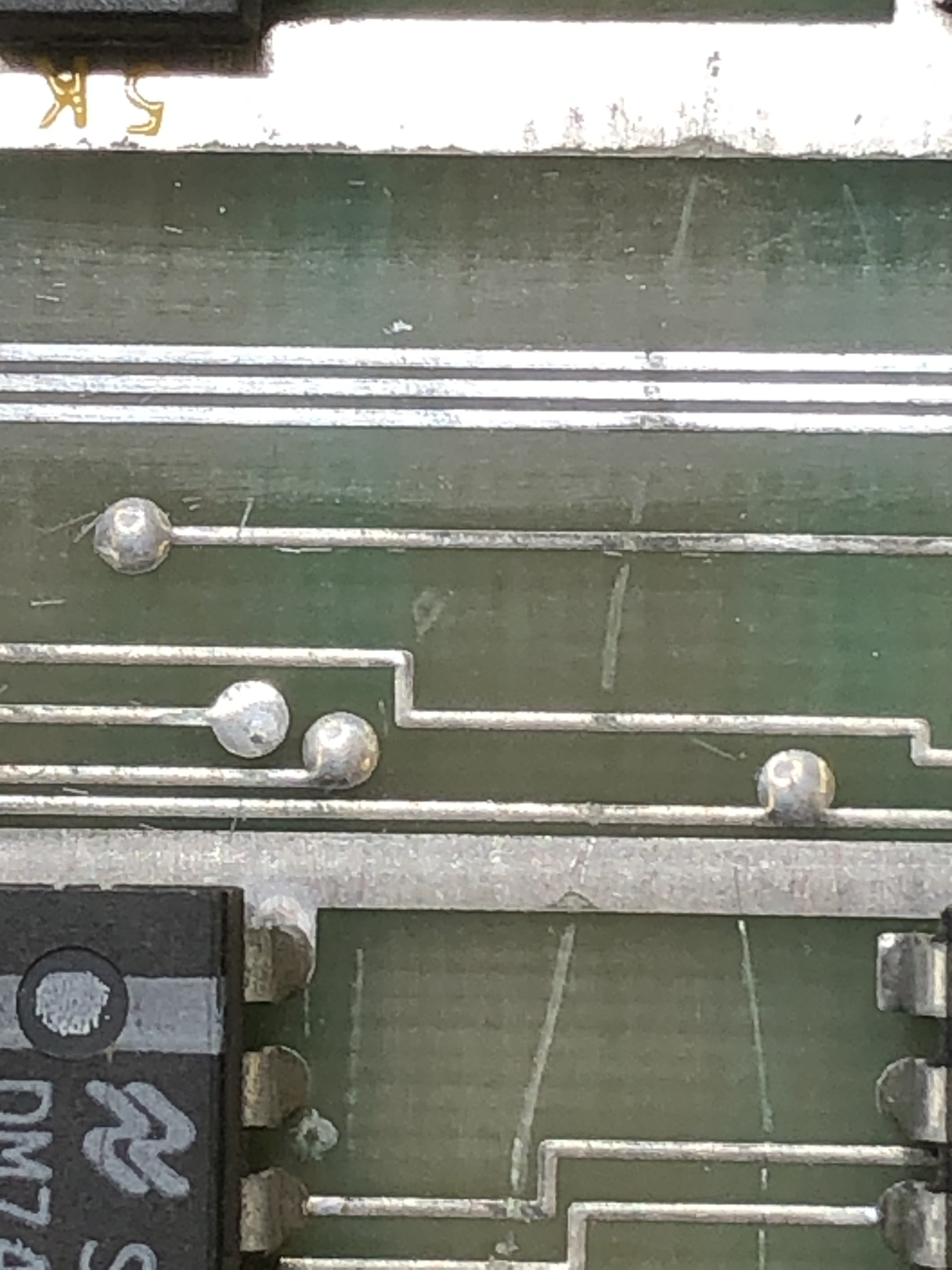
Replacing the dead parts and poking around – I could only get the board to verify it had good RAM, ROM. Parts swapping made no difference, etc. Finally I found the signal at SA12 was corrupted (looked like a short of some kind). The CPU was fine and I finally replaced the LS139@2J – it ran for about 30 seconds and reverted. There is almost nothing connected to this one.. Pushing on the SA12 line on the CPU with the scope probe made the board run.. hmm.. sockets? It was pin 20 right on the corner. Replaced CPU then ROM sockets (and RAM for completeness). No change. Flexing the board was still getting me clean signal – so definitely a bad connection. It wasn’t a short and it had to be software messing up the SA12 line at this point. Then I saw this..

Which was actually less visible than this when I found it..


This is R5 – a pullup resistor on the IRQ line that connects to the PIA which – somewhere in the software controls SA12 which was then messing up the decoding and causing no sound. Except for the self-diag sounds telling me the RAM/ROM were good. On the scope it really looked line a short.
Boards work!
*** Update ***
After a full day of burn-in, power on second day brought “Bad Mathbox Ready Line”.
Lucky it was pretty easy to find – no clock coming out of LS161@9D. Back to burn-in tests.
*** Update ***
The board that keeps on giving. After 3rd full day of power up..

Ram Replaced – board works.. again!
Board #9 – Board in for repair
Star Wars board came in. Status was board was resetting continuously. Had been sent out to two other repair guys prior to me getting it. I’d seen the resets and did a full board maintenance, cleaned chip legs, etc. This takes a couple hours
Once on the bench…

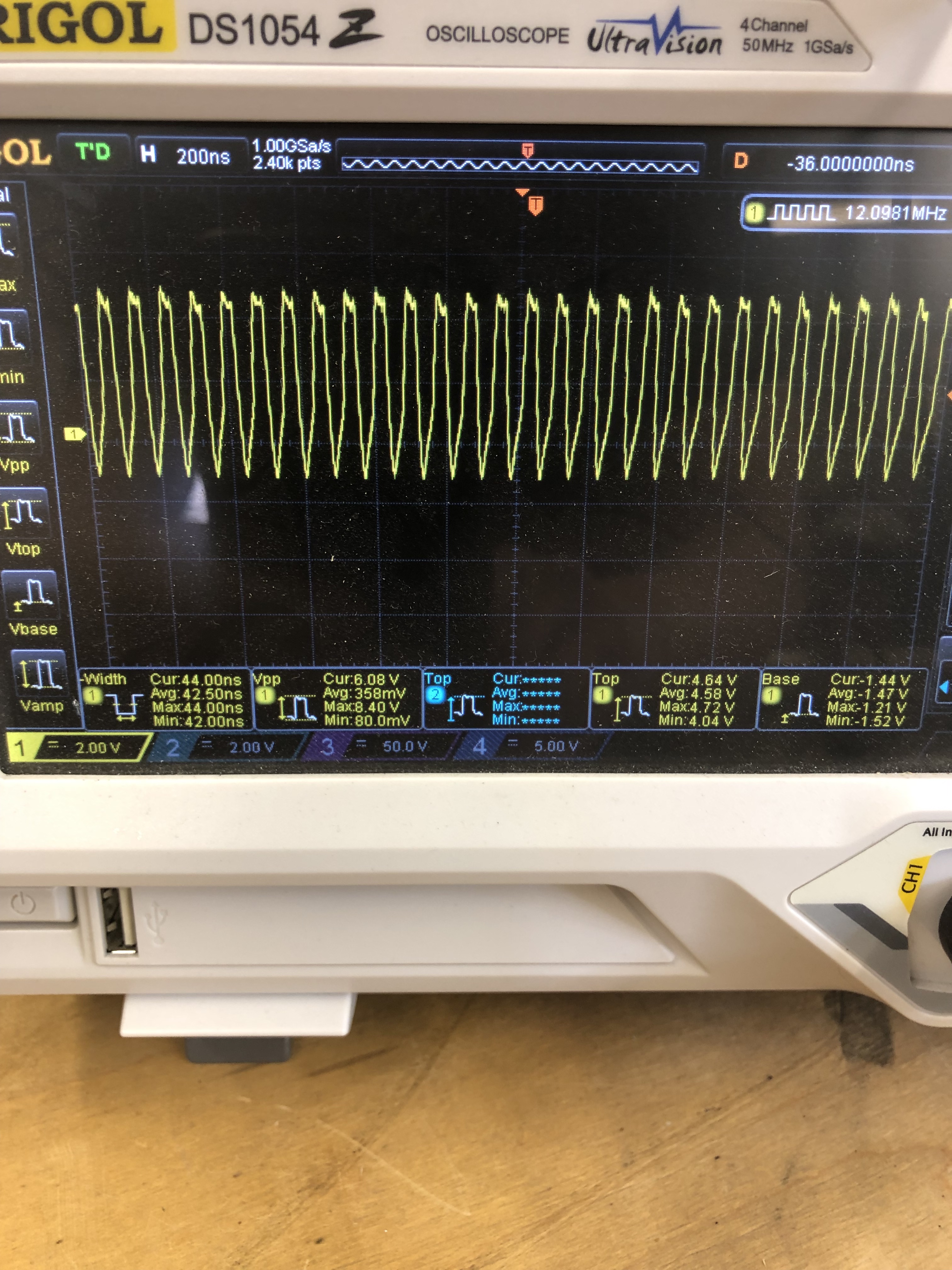
I determined the clock was bad – Original crystal 12.096 MHz. Clock running at a near perfect 3x of that. Replaced crystal. Board works. This type of failure is really due to boards not getting stressed tested enough after the initial work. My repairs include3 x 12 hours days of burn-in + an additional automated 16 cycle power on / power off test day (30 min on, 60 min off). I spread this over a 7 day period to try and shake out any other marginal components.
This board got nearly 70 hours of burn in time just to be sure.
Board works!
Board #10 – Board in for repair
Board was reported to have some bad vectors and problems with the sound. All the socketed chips get removed, cleaned, DeoxIT. Chips not tested by self-test get bench tested in a reader when possible.
Once cleaned and inspected – this stack checked out. All RAM, ROM and vector generator tests passed. Sounds were not working correctly. There was lots of clicking and popping mixed in with the sounds, but no voice tracks.
I started simple and swapped in a good voice chip – no difference. Probing the circuit, everything looked pretty normal. There was a clock signal going into the voice chip – but it didn’t seem like it was processing data.

After probing around and seeing what looked like correct voltages on the chips as far as power goes, I checked my SW sound board and found the difference.

I didn’t take a picture of the ‘before’ – but the clock coming from the 74C04@2F looked like a normal square wave clock going +5v to 0v on the bad sound board. The actual clock should go +5v to -5v. Had to order the 74C04, had not run into a bad one before. Replaced it. All voice sounds restored.
Board works!
Board #11 – Board in for repair
Board was reporting to play blind. Connected it all up at the bench and no graphics as stated. Popped in a new AVG chip and game restored.
Notified the owner that I could stop here, but it is a working machine in an arcade and they chose to do the full board maintenance (chips cleaned, DeoxIT, edge connectors cleaned, 4 day test cycle, etc.)
The interesting part of this machine:


It has an original Clay Cowgill Empire Strikes Back kit. Never saw one in person.
*** Updated ***
Unfortunately this one came back – It had run for many hours.. Dead vector generator. 74LS175@4K died, so a legitimate failure. Running through many burn in cycles again before returning.
****
Board works!
Board #12 – “A New Hope”
Got these three sets to work through. There was actually one set with matching serial numbers so I shuffled them around and started with it. They were all reported to have varying degrees of issues. One was worse than the rest I was told, seems I picked that one first.
I started with just the CPU and AVG board. Setting them up and connecting them to the FPGA Catbox – there were a number of problems. Including my config file was a little messed up. After I sorted it out I had 3 bad RAM and the 6809 CPU was not only bad, it was corrupting the testing. I like to use the edge connector vs. the CPU socket with the tester. Once I removed the CPU, testing went a little cleaner.
After spending some time messing with RAM, verifying ROM and doing some vector generator testing.. I finally booted it up and ran on the scope.

The first time through I literally watched the original Atari AVG chip die right in front of my eyes. I got a bunch of game vectors, then a vertical line.. then nothing.. Popped in a replacement and got this. Game running, no fighters, no stars. Progress!
Now that the diagnostic code is running, I was able to connect to my monitor and see what was going on.

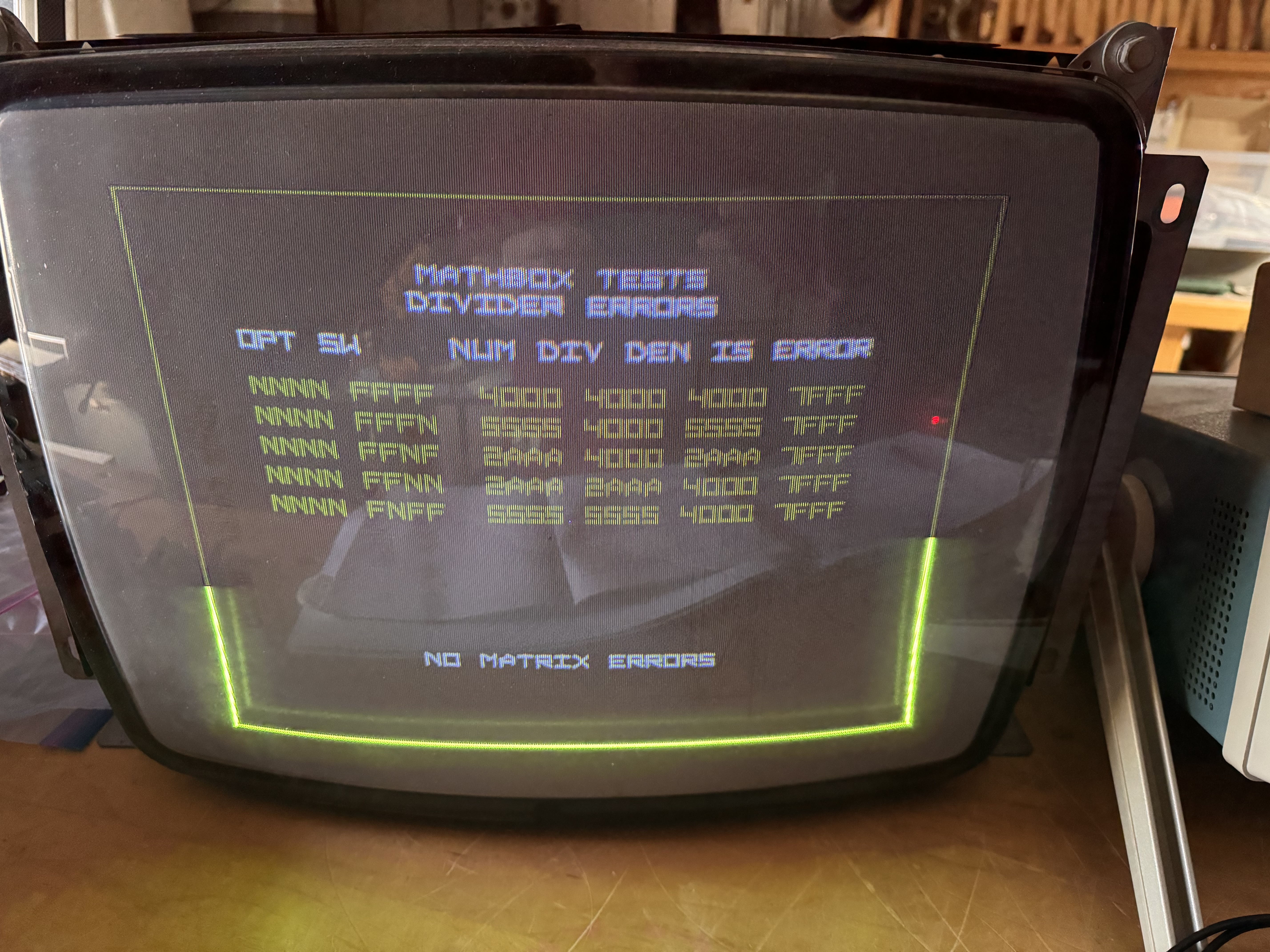
Going after the divider errors first – Looks like it is doing nothing at all. The outputs all being FFFF (except the last one?) made me look at the clock going into that circuit. Star Wars seems to have a lot of different clock generators.

Checked the LS191@8R – No output on Pin 13.. Replaced it and we now have Divider clock!
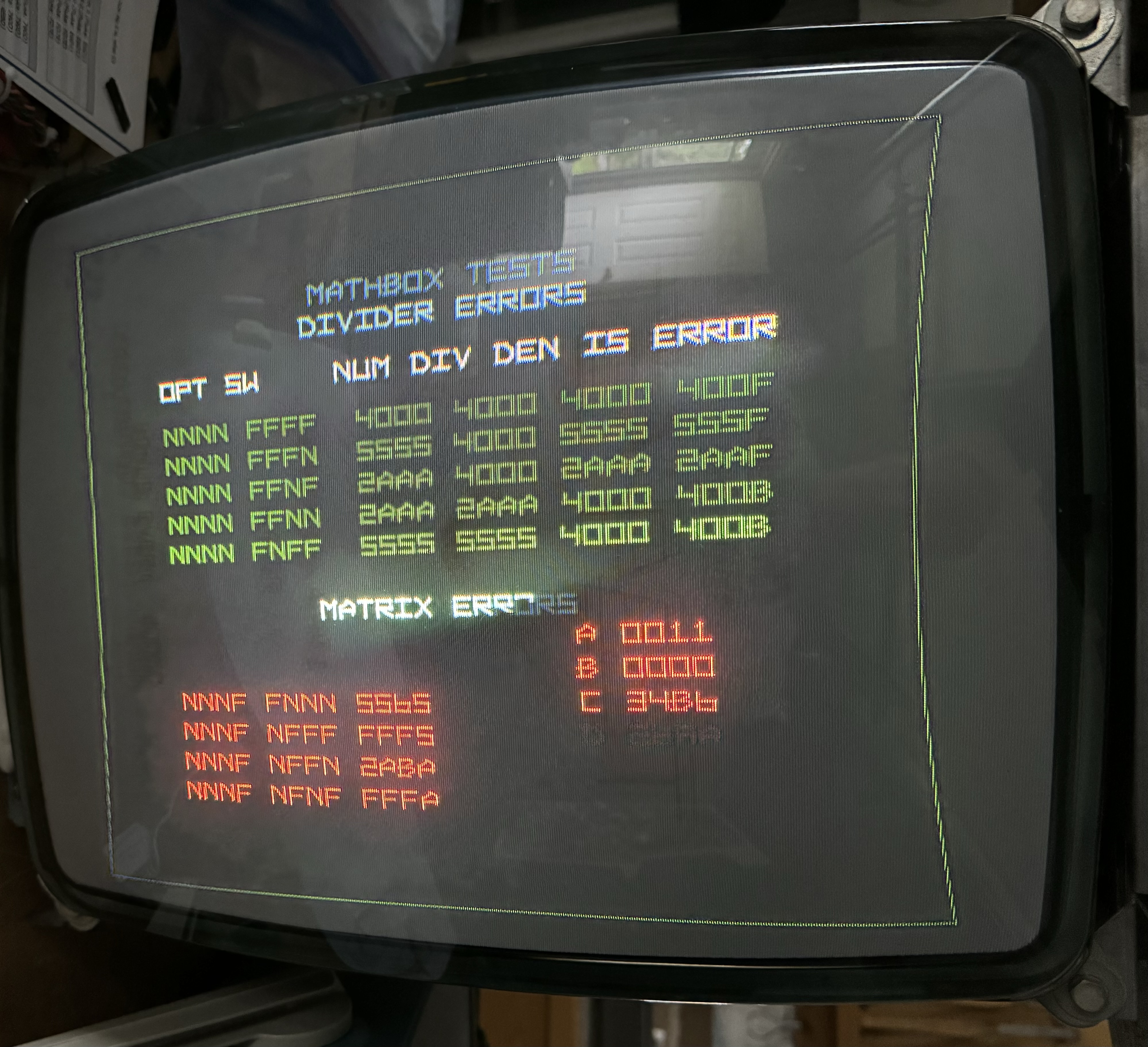
Much different data from the Divider now. It wasn’t running before, now it’s just doing bad math. The tests are #21, 22, 23, 24, 25 from the troubleshooting guide. The Divider circuit is made up of a handful of chips. When the last 4 bits of the error are F’s like this – piggybacking may be the quick answer. I poked around a bit but really – the first chip I looked at was the LS299@7M. It controlled the lower 4 bits of a shift register. Piggybacked one on and cleared the Divider errors!
Down to the Matrix errors above.. These are test#17, 18, 19, 20 – included are the A – Accumulator, B – Block index counter, C – Accumulator Adder Test, D – Subtractor Test on the right. Again the F’s in the result give me hope that a piggyback with find the bad chip. Tried out a few and the LS165@7B cleared the matrix errors. Great!
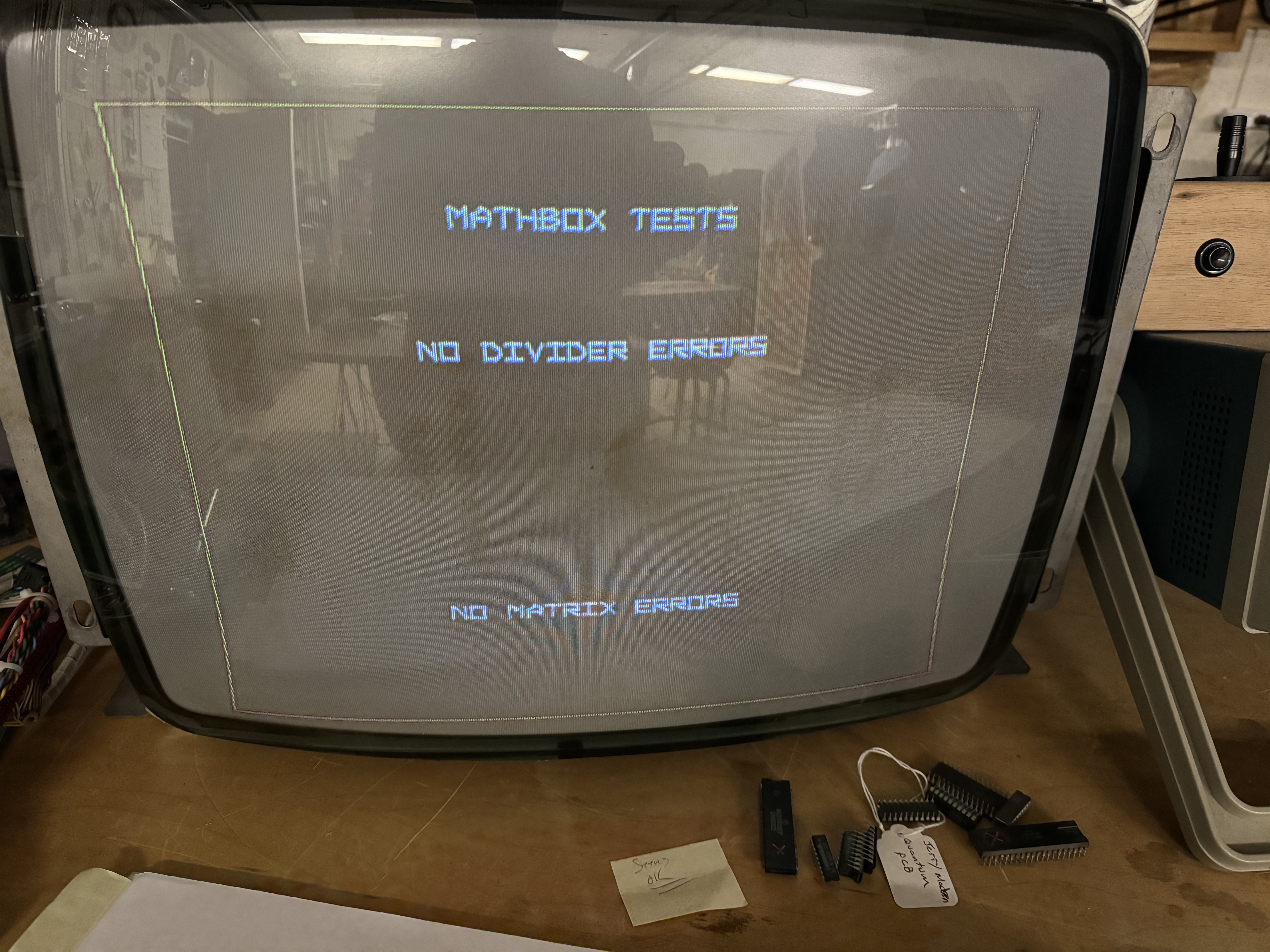

No errors. Still no stars and no ships. I chased this one around a little bit but I knew it was related to the pseudo random number generator circuit. I had not done my normal board maintenance at this point. Cleaned all the chips, Deoxit sockets, etc. I decided to move on to the sound board before tackling the stars.
Cleaning the sound board, the TI voice chip was so rusty it disintegrated. Got replaced. The CPU partially worked at first and I chased weird issues with it before I knew it was just a little dead. Thankfully it died the rest of the way and got replaced. Sound board works great now. After getting it all set up again, the stars and ships showed up. Maybe it was just dirty legs, etc? It was not to be, it ran for many hours. But it will fail and not generate the random number data occasionally.
Here is one view, the random number seems to ‘increment’ down the sides of the screen or blink in a corner. Back to the bench. I’ll note here: I chased this a little longer than I should have..
It was very inconsistent at first, some times it would fail and others it would only on a cold boot. As the board got more hours on it, it seemed to fail on cold boot more consistently. I spent more time looking at this circuit and I could trick it into restarting with a warm reset or grounding a pin on the LS299. The interesting thing was if I reset the chip by grounding pin 9, it wasn’t immediate. The stars would return at a scene change.
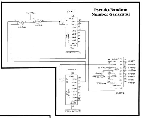
I probed the input signals PRNGCLR and PRNG and it appeared they were running as designed via logic comparison. The LS299@4D was the same date code as the one in the Divider circuit and made the most sense to replace. I popped in a new one, but the same issue persists.
Probed around a bit and I can almost make it happen at will now.. when it works, it works… which makes me think the LS164’s are ok? But maybe one of them is corrupting the reset signal .. I went to the beginning and replaced the LS259@9L/M that controls it all in the first place..

Seemed to work for a while, but that was not the problem child. The only control signal left is PRNG or the LS164’s. I followed the control signals around and learned more about them, they were changing frequency with the star field/background – regardless of getting stars or not.
The LS164’s in the pseudo random number generator are Fujitsu, one of them being the shiny kind which I have had lots of failures with in the past. I’m replacing one at a time. Maybe they just count when they feel like it..
After replacing the LS164@5C, I had one failure of the star field. Then I remembered something about this topic in the troubleshooting guide:

I should have started here. I’ve worked on a bunch of Star Wars sets now, but had not run into this specific issue before. Experience +1. I managed to make it fail one more time after 30-40 power cycles. I tested for white noise and it was missing (good) but got a little excited and should have tested PRNGCLR before resetting. I replaced the second LS164@5D and have not had an issue since.
Board works!
Board #13 – “The Empire Strikes Back”
I’d borrowed a few parts from this board to get the first one working. First thing was to repopulate missing chips, etc. After that I verified all the ROM and RAM good, even the vector generator was good. Maybe with reshuffling the boards I picked the two that would work?
No..
Once I verified the video on the scope I connected to my monitor:

No stars and ships again!? I quickly used my new found trick from above and determined the pseudo random number generator was working and generating white noise. That was fun.

All the tests are good except the B 0000 – Block index counter test failed.

First guess would be one of the counters failed – quite common.

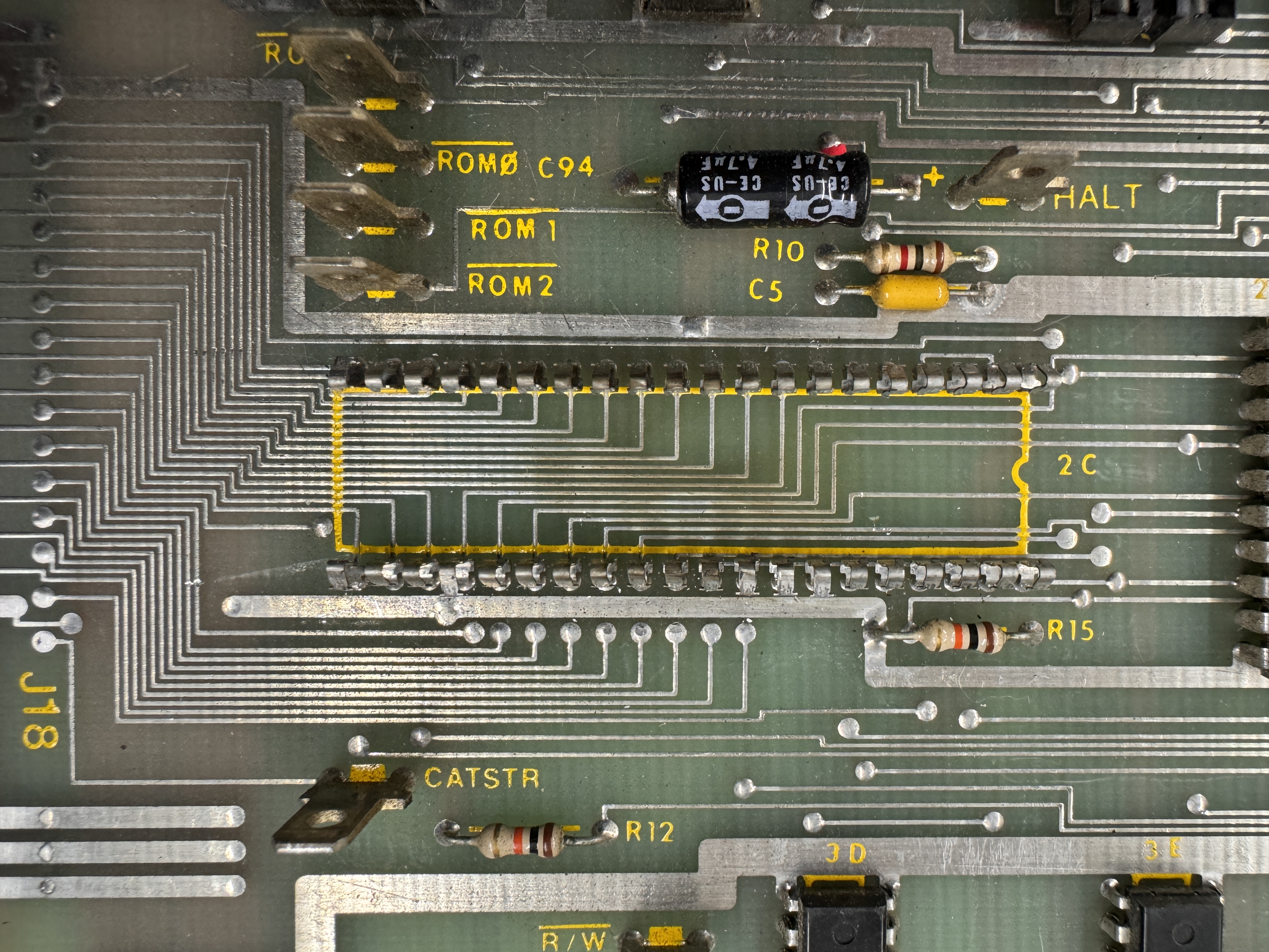
However someone purposely cut the traces. Quick repair on that but the issue remained. I determined that one of the pins on the LS191 was stuck and I was going to replace it. Except whoever did this purposely solder blobbed 2 pins together on the solder side. One pair on 3E and one pair on 3D. Once I cleared them, the error cleared AND the stars and ships returned.
Turning my attention to the sound board, it didn’t work. First thing I did was check for clock – there was none AND the CPU was burning hot. Third bad CPU from this trilogy of boards. Put in a new one, still no clock. Test point #2 for CPU clock comes straight off the backplane connector – no clock.

Sound board connector has a couple of pins bent back. Small adjustment with a dental tool and we have clock and sound. Using the sound board self test – I determined 2 of the Pokeys were bad (ouch) One provides static/white noise, the other was missing a sound channel.
Board works!
Board #14 – “Return of the Jedi”
This set turned out to be pretty dingy looking. They were worse than they appear.


All three boards made a trip through the sink. A small nail brush scrub over the sockets does a nice job of cleaning up the exposed parts of the contacts.
The first two boards had borrowed parts cascading down to this one..

This is just socketed stuff from the trilogy. After repopulating with the existing and replacement parts, connected up the CPU and AVG board. RAM tested good, ROM tested good. Did I pick the two boards that only had bad socketed parts? Sorta..
Powered up on the scope – game is running!
Now the circle is complete: No stars, No ships, except for a little twinkle of falling stars now and then. You can’t make this stuff up. I quickly determined the pseudo random number generator was working with the trick above. I decided to swap in known good Instruction PROMS. One at a time. Stars returned with PROM 112. Nice…
On to the sound board. It was a complete mess.

This is the washed sound board. Voice chip was completely rotted. I had already borrowed the RAM and CPU. Had to swap in known good Pokeys for testing. Got it powered on and the voices worked pretty well, but the game sounds generated by the Pokey had a bad echo effect.
The echo was being caused by the delay circuit. Jumping pin 6 to pin 4 on R5106 confirmed that by eliminating it completely.

Checked the clock circuit to see if it was messing up the delay.

It seemed to be pretty close to my working board, but a couple of signals on the 556 chip were a little off.. Then I noticed Q4 was bent up funny (someone’s thumb at some point smashed it). Quick check showed that is was not good. Replaced it and all game sounds restored! Phew. R5106 is pretty much unobtanium had it been the issue.
Board works!
Epilogue
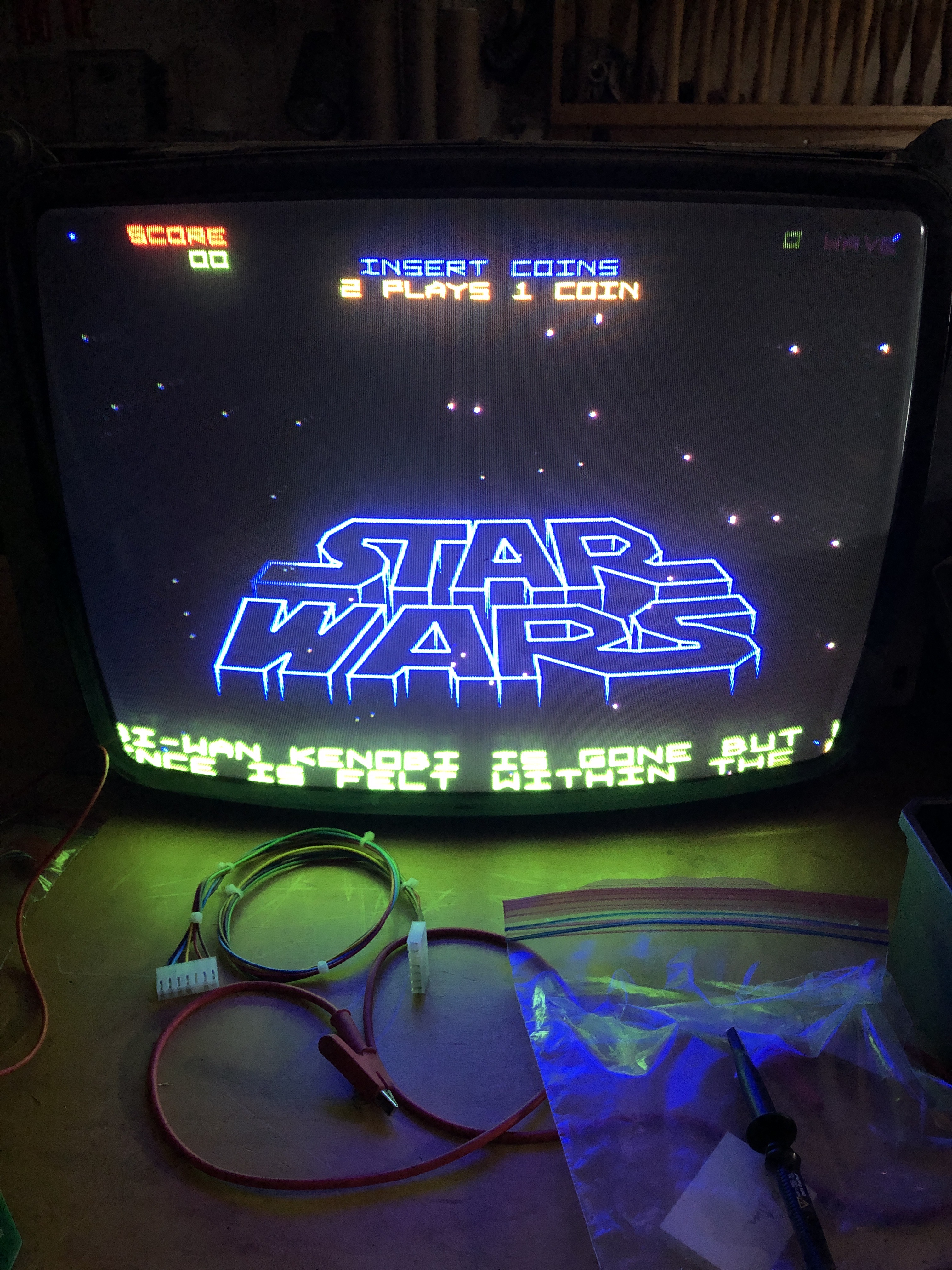
Even though every monitor is different, I adjust the stack to my Amplifone before I ship them when boards come in completely dead like these. Typically I use the diag screens and set XY size, linearity and BIP. No problem.
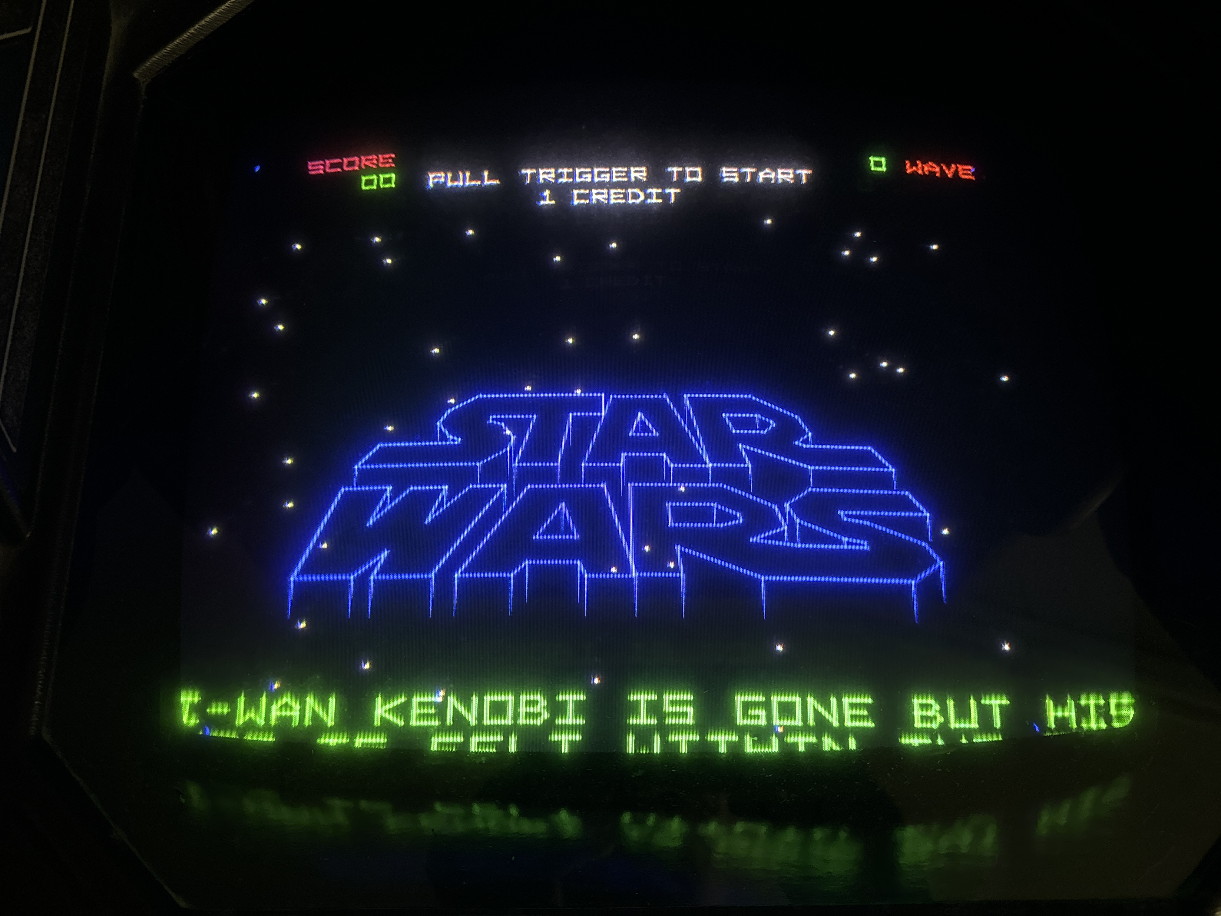
One of the stacks after adjusting came up with this image..

Adjusting to a test screen is one thing, but this is rather ugly with disconnected letters. A great way to get this really nice is to use the “freeze mode” DIP switch setting – switch8@10D. The game board is pulled out of the cage to adjust the pots at this point, so it is easy to access. Wait until you see the logo start to scroll and flip the switch to ON. The game stays perfectly still. If you hit the left trigger on the controller, you advance the screen one frame at a time. Fire away until you get the logo nice and big. Don’t walk away and have a steak dinner – but leaving the screen stationary like this for a couple minutes is no big deal. Adjusting the X and Y BIP pots allows you to line up and close the letters nearly perfectly.
Oddly enough – switching back to BIP test in diag mode looks terrible.

I prefer my letters connected and I didn’t see any ill effects elsewhere in the game. You can freeze in any scene and look!
I use freeze frame for adjusting the shooter screen too.
Many Atari games have freeze mode. I’ve used it to ‘quite down’ a PCB when I’m searching around for issues with a scope.
Finally, most of the Star Wars PCBs do not even label the pots. When they do – they are not legible.
My Cheat card:

I have it printed – I should make it a Tee-Shirt.
Board #15 – A board I picked up off KLOV as a derelict.

This set had surface oxidation across all three boards. I started with removing all the chips (that were there) and washed the boards. The AVG and ROM105 socket on the AVG board were missing..
After washing I went over the parts side traces with the fiberglass brush to clean up all the surfaces and make sure that there were no little shorts mixed into them.
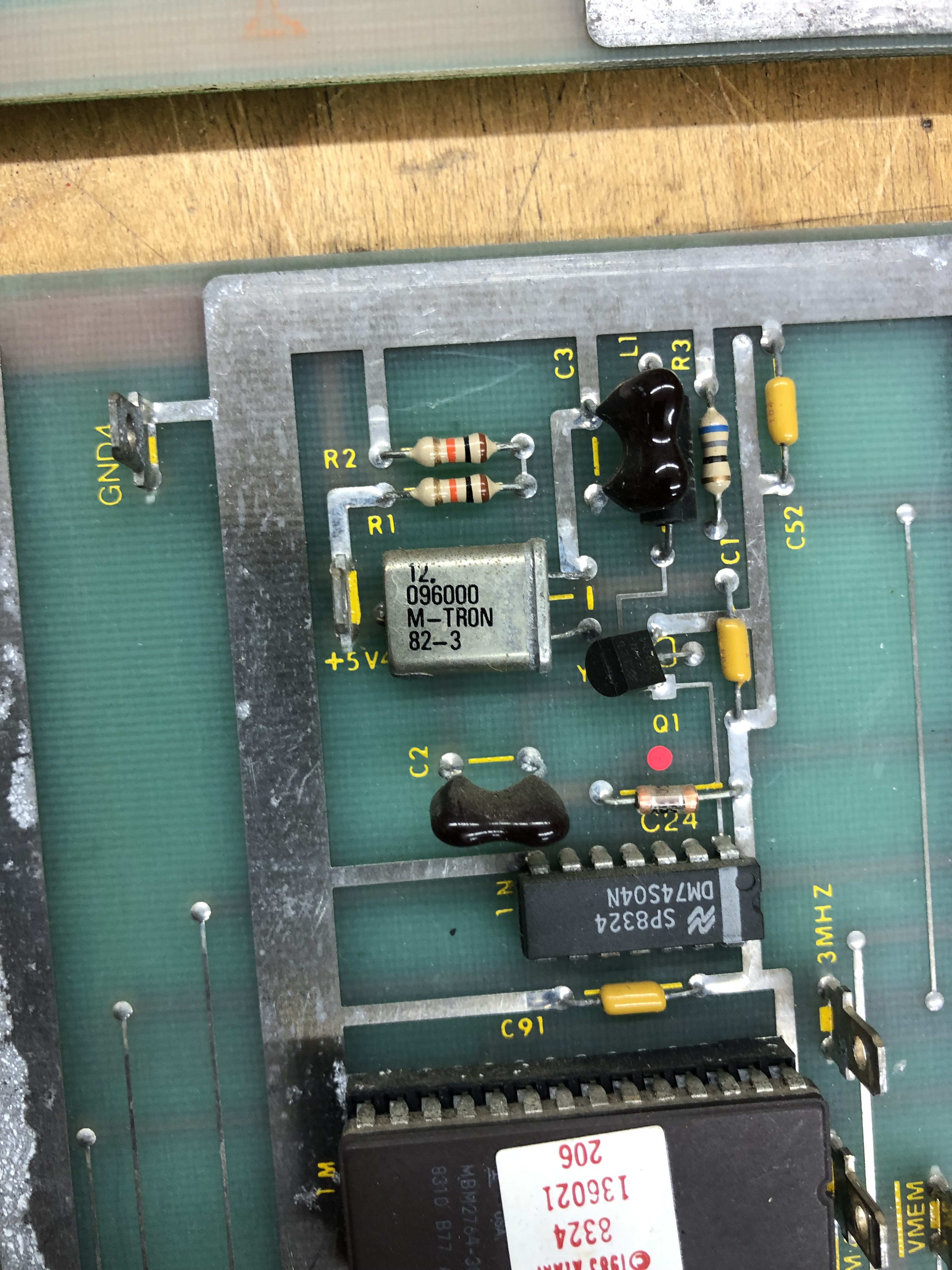
Decided to start with the sound board. I had another Star Wars on the bench at the time. One thing I’ve seen on many Star Wars boards are these purple capacitors.


Pretty much all of them seem to leak. One of them was blown apart, but still showed it worked?!
Got all the chips plugged in and it was stone dead. To start, the CPU was not getting clock. Wiggling it effected some of the signals and the CPU socket looked terrible. I replaced it. After that it was still behaving badly. Lots of confusing signals running around the board. Finally I determined the LS139@3J was taking line select signals IN and just mirroring them OUT to all the select lines enabling all the Pokey’s at once corrupting the busses. Once replaced, I determined the 5220 voice chip was bad and corrupting the bus.


Of the four Pokeys, two had broken legs. Using a Dremel and a small round bit with a flat head, I grind out a notch and expose the top of the pin in the plastic housing. I little solder and flux and I attach a new leg. When done I put UV cured resin in the notch to help secure it in place. Both broken leg Pokeys turned out to be good! I only had one bad Pokey from the four.
Last part of the sound board was the audio was very muted. Bypassing the R5106 chip (Pin4 <-> Pin 6) fixed that. Unfortunately they are unobtanium. It adds a bit of depth to the audio – sorta simulated stereo. Jumping pin4 to pin6 restores the sound, but it sounds a bit flat.
Sound board works!
AVG Board:
First I repaired the AVG socket and ROM sockets. However this board has a lot wrong with it. I determined there was no VG clock. It traced back to LS244@1P Pin 5 – No VMEM signal which is part of the clock generator for the state machine. Replaced it and now I have clock.
Used signature analysis on the state prom@4B and there was no OP0 signal@pin1. Popped it out and determined it was bad. Using a PROM/EEPROM adapter I was able program a temporary replacement and get OP0 running, but still no halt. Continuing to look at the state machine, LS157@4A was not outputting any signals. Piggybacking a chip caused a glitch in the vector timing.. That’s good! I replaced it and restored the HALT, Great!
Next test is CENTER – however – it was not running. The only other command that seems to be running (correctly) is draw short vector. I spent some time tracking down the root cause of this issue. Based on the symptoms, it looked like the vector timers were not working correctly. Which they weren’t, but the cause was external to the actual timers. Tracing through the circuit lead to many timings that were off in the ‘circle logic’ of the VG.
OP0 on Pin 7 was the signal that was way off in pulse width as compared to a known good board and is where I focused the search. It was off due to LATCH1 pulse width timing.

Checking the State Machine one chip at a time using a comparitor showed all of the chips working correctly. Signature analysis of the prom@4B using the catbox showed it was fine. I was uncertain of the signals coming out of the BCD decoder @3D. For the first time, I used the FPGA Catbox as an old school Atari Catbox and checked the signatures coming out of LS42@3D. They were all good too. Ok – so the state machine is good AND I have better validation of it moving forward.

From here I wanted to check the signatures of the data shifters, but they were not cooperating. I could not get them to sync up on a known working board consistently using the FPGA Catbox in Atari Catbox mode. However – using the FPGA Catbox I was able to load -1’s into both X and Y and look for all the 1’s rotating through the DVxn outputs. This was the breakthrough moment because I could see all of them working on my good board AND my bad board. On the bad board, the pulses were MUCH longer.. Working backwards the ENORM pulse coming into the LS194’s was the same length as the oversized pulse of the outputs.

That lead me here, where as it turns out the input from 6J@pin10 was being sent out (inverted) on pin8. The 74S10 was performing bad logic! Replaced the 74S10@6J and the vector generator timings all came back to life!

Finally something I can see. Connected it my bench 6100 and the Z axis was locked on, retrace lines everywhere.
Found this quickly. No outputs on LS164@8N. Replaced and vectors being drawn without retrace lines. AVG board works!
*** Spoke too soon ***
It wasn’t noticeable on the scope and I didn’t really catch it on the bench 6100 – but on the Amplifone it was very visible. The Linearity test had a bit of a studder, but the letter scrolling is very stair steppy..
Didn’t take long to find. The LS273@5E was putting out bad data on pin 5. Replaced it.. Smooth scrolling now!
AVG board works!
CPU board:
Once I got it connected up and populated, the RAM and ROM checked out. The vector generator board was not working when I first powered up this board. I popped a known working AVG board and the CPU board is mostly running! Diagnostics come up and I get “BAD MATHBOX READY LINE”. C21, C73 were broken.
I started by checking the Matrix Processor Clock area and it seemed to be ok, but not doing anything.


In the past I’d had trouble with the Multiplier/Accumulator Clock and happened to check the output on LS161@9C – it seemed to be a floating pin12. My HP logic comparator also showed a bad pin12 (and pin14). I pulled and tested it and it showed bad, but it did not solve the problem. However, it did activate LS161@10C and now that it was getting signal from 9C@pin12, it didn’t seem to be counting correctly. A quick piggyback and the READY LINE error went away and my new errors showed up. Progress!

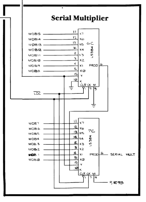
One thing on this board, I had a prior repair and ‘borrowed’ the AM74LS384 (AM25LS14APC) chips since I didn’t have any in inventory – turns out both on this board were bad, so they had been replaced prior to starting this section.
From here decided to work on the matrix errors first.

It took a little hunting, but the LS165@6B was the issue here. I missed taking a few notes and I don’t remember exactly what it was doing.. What’s nice about this particular diag screen is that it runs continuously. Piggybacking chips or probing with a grounded test lead and grounding suspected chips narrows the search by changing the display output.
On to the divider outputs. All 0000’s is a pretty strong clue that no output is being generated.

Piggybacking a LS299@7D caused the divider errors to glitch and show outputs. Replacing the chip got me here.
This is a step forward! Probing through the divisor circuit, I found that the LS83@6N had dead outputs.. These are not to be found it seems, luckily Centipede has them and I was able to ‘borrow’ a couple. I did fix an issue, but still no differences.

Continuing, I piggybacked the LS374@5L and got half the answer.

High order bits on the ERROR seem to be good. It also changed some of the low order bit errors on the last two rows.

I started testing the other LS83@6M also had some dead outputs. Notice the low order bit ERRORs have changed. 40FF-> 407F, etc.
Here is where it went off the rails, somehow a tiny solder splash happened on the the parts side, but it had me chasing ghosts for a while corrupting the MATH BOX data bus. Once I got past that nonsense – replacing another LS374@5M cleared the remaining divisor errors.
Board works!
Board #16 – Board in for Repair
Received this one in from an operator friend to go over. It was reported to have a main CPU board issue, messed up vectors and a sound board that was resetting.
Board came in with known 3 bad RAM, the AVG Chip, ROM 105 and the voice chip were missing. First thing I did was connect up to the tester and started verifying ROM and RAM in place. I also noticed some of the fingers on the backplane/interconnect were oddly bent. I corrected them with a dental tool.
After replacing all of the known missing and bad components, there were RAM errors. I spent some time cleaning up the parts side traces and found a short causing the RAM error.

This was tiny – but killed some of the RAM signals nicely..
On to the AVG board – it had the bad RAM. Star Wars is very sensitive to RAM speed and getting them moved around so that the PCB was happy takes a little experience.

C4 was broken in the X part of the analog section. The tiny little cap causes linearity distortion when missing. Easy fix on that.
Sound board: Voice chip was missing – got replaced. Under test, all of the generated sounds were good – no voices. I’ve run into this before..

The 74C04N@2F (CD4069CN) has been a failure point I’ve bumped into before. It’s output is the clock for the speech chip. Voices restored.
The last issue took many hours of hunting and burn in time to finally uncover.
While watching the game on the scope, these vectors appeared..
Some of the Star vectors were going way off the playfield on the left and right side. This was definitely a chip doing bad math. The self tests were not catching it. At first it seemed thermal as it would go away after a few minutes. I tried to find this a bunch of ways – nothing was jumping out. I decided to force the issue and left the board running overnight, then during the day. Then I created an automation for a smart outlet that turned it on for 10 minutes and off for 10 minutes – 60 times. What came of all that was it did slowly get worse AND the symptoms became more noticeable.
The towers glitch during the sequence – this was new and it was relatively consistent.
In the end I was able to narrow it down to a chip I’ve never had fail. It was also difficult to acquire, not readily available.
The 74LS384 (AM25LS14APC on every Star Wars I’ve ever worked on..) was the cause of the graphics issues. A little on-line research showed that it was involved in these sorts of math calculations.
Board works!
Board #17 – Board in for Repair
Reported symptoms: Board runs DIAG screens normally, watchdogs when set to game mode.
Performed all normal board maintenance, removed chips, Deoxit legs, etc..
- Ran board self test – everything checked good
- Ran CATBOX RAM, ROM checks – everything checked good
- Checked RAM on the bench with the Inquisitor – RAM checked good
Looked for other issues, however, replaced RAM@2F/H.
RAM was not viable at game clock speeds..
** Update **
During the burn in testing, the game graphics developed a glitch. Stretchy tie fighters. I had not noticed it a first while making the video..
Back on the bench… worked on it a bit more. The self tests do not pick up on those sorts of errors, they are a little more tricky to hunt down.. Finally found a bad LS83.
Board works!
Star Wars #18 – board in for repair
Got a repair from a work colleague – the reported issue was “The game runs slow”. The boarded needed to be cleaned and I did all the standard clean the board, chips, Deoxit, etc.
Connected up the board on the bench (without the sound board) and everything worked as expected. Connected up the sound board and the sound test was off. Determined there was a bad Pokey crashing the board. (not sure which position, they got mixed up during testing).
Going back and testing, the crashing of the sound board DID cause the game play to run 20-30% slower (an approximation – no real way to measure). I went back and forth a few times with the bad Pokey to confirm.. The crashing must have disrupted a handshake between the boards enough to slow things down.
Replaced Pokey
Board works!
Star Wars #19 – 4 boards in for repair
Friend of mine had 3 Star Wars sets he picked up 15 years ago.. A friend of his had a set that had started watchdogging. Big box of Star Wars showed up..
This set had a Star Wars Empire Strikes Back kit installed, I de-converted it to test. Hard to see here..
The CPU socket had a loose pin. Replacing the socket and cleaning up the surface traces with a fiberglass pen resolved the issues.

Board works!
Star Wars #20 – repair 2 of 4
This set had a number of issues

However – they all start the same way. Remove chips, clean legs, Deoxit… These were pretty clean, but I washed the boards since 2 of the sets will eventually be sold.


Some highlights from this set.. I’ve never seen these purple caps on the sound board not leak. The record stands.. Replaced them. During testing, there was memory corruption.. A few swipes with the fiberglass pen on the surface side and cleared up. Finally the edge connector is some odd replica version – it doesn’t fit into the cage correctly and more importantly, it doesn’t work. I checked for shorts and everything seems fine.. but the boards will not run with it.. It has an extra row of holes for a 4th connector – which makes no sense either..
Other items from this set: State PROM was missing and the AVG chip was no good. On the sound board the 6809 processor was dead. Ran the full 3 day test cycle.
Board works!
Star Wars #21 – repair 3 of 4
Third board of the Star Wars set. This one was reported the controls were stuck up in the corner.

This Analog to Digital converter@9K was the issue, replaced. The voice chip on the sound board disintegrated upon removal (common with these silver leg chips), replaced.
All other maintenance completed
Board works!
Star Wars #22 – repair 4 of 4
This one did not boot – did all board maintenance – board works!
