Thoughts of a first timer..
Once I got everything back together and the machine fired up I was in a position to actually do some testing. When I first got the machine, I determined there was a sound issue and no high score retention. During bench testing of the CRT – I was having trouble with the blue gun.. It worked – but there was no blue scale – it was either on or off in the test pattern.
Guys who have been doing this for years have a process and a routine – but this is my first time.. I had checked the power brick and was 100% certain it was good. Then it hit me… The ARII board and the PCB have voltage test points all over them – I’ll check them all and see whats going on.
PCB Test Points
Test Point Actual Voltage
+5v +5.063v
-5v 0.569v
+15v 0.001v
-15v -15.12v
+22v +24.72v (unregulated)
-22v -24.93v (unregulated)
-30v -14.00v
ARII Test Points
Test Point Actual Voltage
-5v -1.263v
+12v +12.08v
+10.3v +12.66v (unregulated)
-sense 0.187
+22v +24.86 (unregulated)
-22v -24.87 (unregulated)
+Sense +5.125
36v AC 36.91vac
All this stuff wrong? Why is anything working at all? I was rather surprised, in fact I thought I was doing a few things wrong at the start. After digging into this a bit further – the machine is more that a power cord in and a screen showing the game. All of these are little power supplies for all of the different circuits that require different voltages.
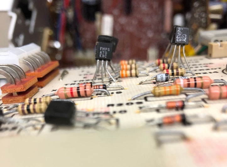
First troubleshooting task was the blue gun on the CRT. After watching Randy Fromm videos – his video circuit troubleshooting advice made sense. Each color (Red, Green, Blue) have identical circuitry which makes it easier to diagnose. One of the transistors on the interface board (one of the blue ones) read just a little different than the other two.
So I swapped the questionable blue transistor with the green one. Problem moved to green! Bad transistor identified.
On the ARII board – The -5v test wasn’t working. Checking the schematic – there is a -5v regulator chip. I put the meter on it, no -5v! Another bad chip identified. Reading the schematic, -5v is part of the audio circuit. During testing – the audio did weird things after 10-15 minutes of play. Maybe its resolved? Time will tell.
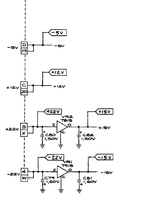
On to my +15v issue. From the schematic – There is a 7815 +15v Voltage regulator (VR2). It should be +22v on the input side and +15v on the output side. Quick check with the meter.. Bad voltage regulator! Another chip identified.
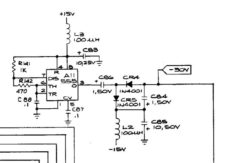
The good part of this is that the +15v is part of the retain high score circuit feeding the 555 timer chip. My -30v issue is also in the same area. If I replace the +15v regulator – It should fix the -30v issue too, right?
Well I replaced the voltage regulator and there was no change on the -30v side. A quick check of the the diode and capacitor said they were fine.
The only thing left is the 555 chip. So I socketed and replaced it. Problem solved! -30v at the test point.
UPDATE:
After I did all of this – I ran into an article Bitslicer -30v power that explained how this part of the circuit actually works. I’ll have to re-read it a few times so I get it.. but very impressive explanation.
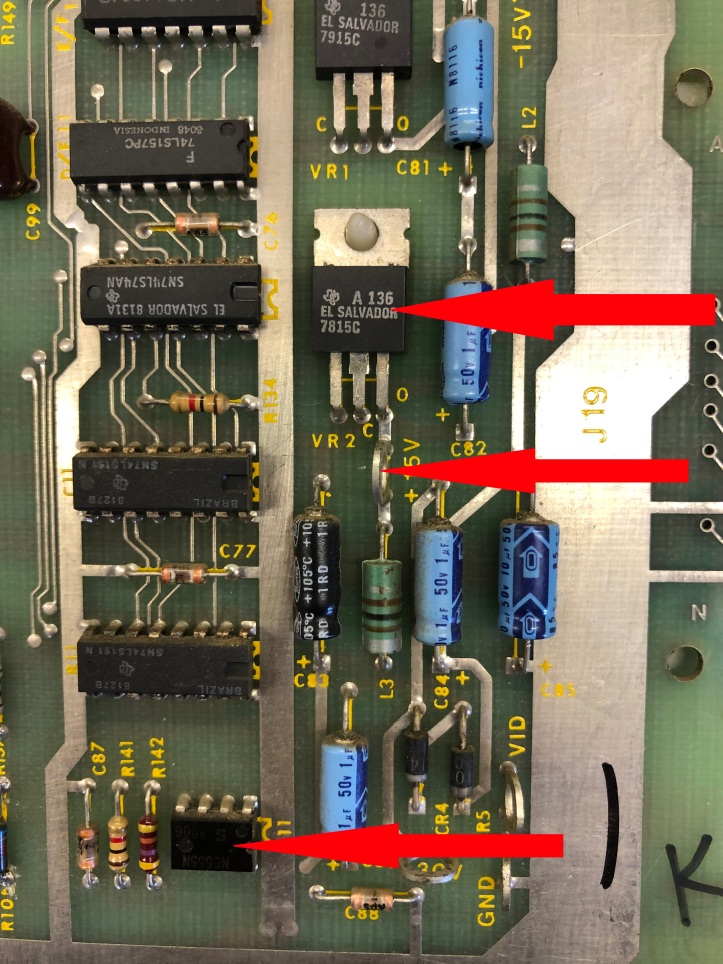
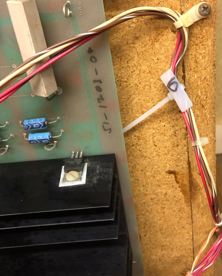
Here is the 7815 voltage regulator, +15v test point and the 555 chip – before replacing. All pretty close to each other and very serviceable.
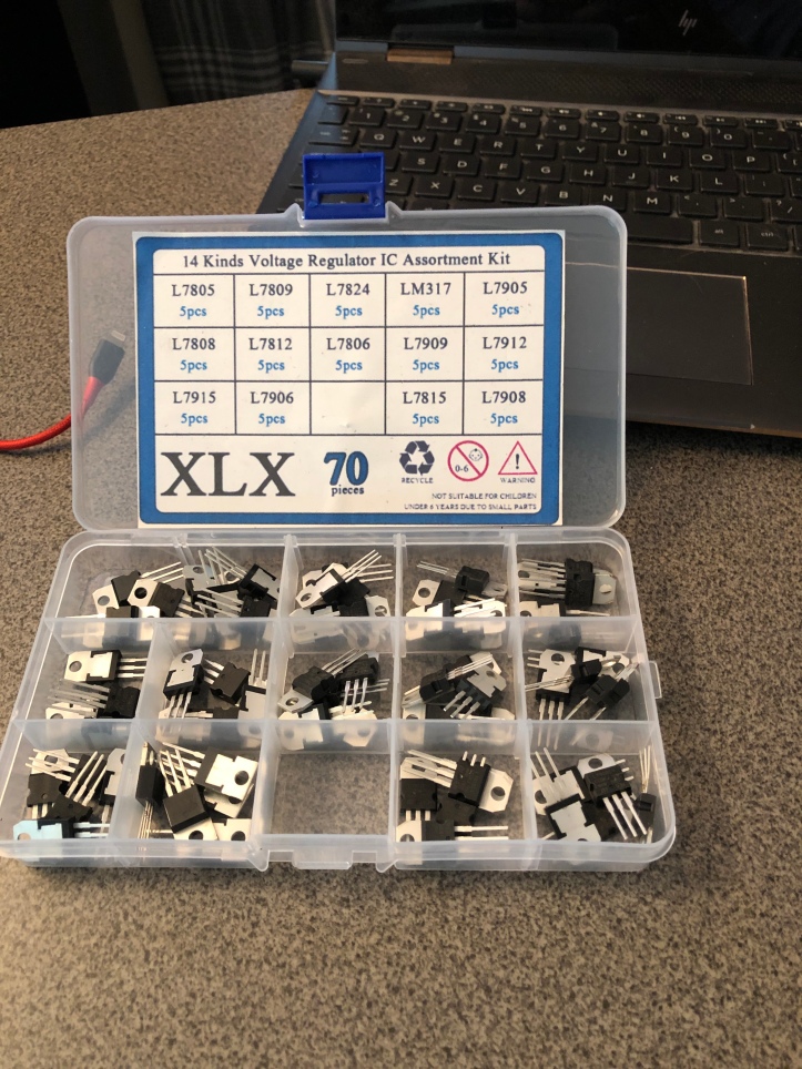
Purchasing parts: Its a real balancing act. If I could plan and make big purchases – I’d get everything from mouser or the arcade repair sites that keep a lot of the parts on the shelf. The issue really comes down to shipping. A single +15v regulator costs $0.49 at mouser.com – shipping is $7.99. Not an issue when you have a cart full of stuff. The kit above has a selection of 70 voltage regulators (many also on these PCBs) and was delivered by Amazon Prime for $17. Same story for transistors. $0.15 for a single. $8.99 delivered for an assortment of 250. I’m 100% certain they are not the same quality – but everything is a trade off. If you can be patient (I’m not) – make a big list and get a bunch of stuff at once.
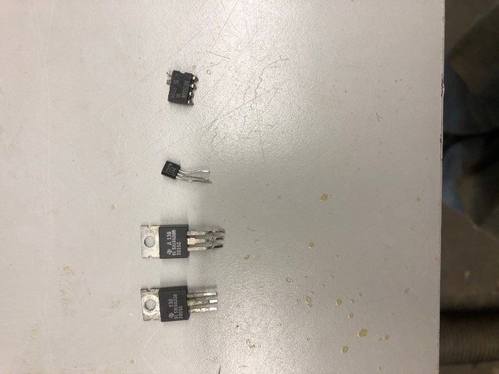
Here are my offending components at the moment.
Game status:
- All of the power test points are showing proper voltages.
- Still need to test high score retention and the audio.
- CRT – still needs converging and testing
- PCB – Not convinced the video is outputting correctly. Need to test with a known working monitor.
All of this checking, thinking, looking at schematics happened over the course of a week or so.. Once I got the feel for it – it starting going faster. It was pretty cool to look at the schematic – look at the chips around a test point and go.. hmm.. that should have one voltage on one side and a different one of the other – then find a bad chip – replace it and get the right voltage. The Atari PCB schematics are really good about supplying great detail.
I’m now looking to do the same sort of thing on the K4600 monitor. The schematics are not nearly as good. More thinking, looking and testing to do.

[…] Working on the electronics.. […]
[…] Working on the electronics.. […]
[…] Working on the electronics.. […]