
My approach to fixing PCB’s – When you are just starting out.
Digging into the restoration of my Centipede machine lead me toward fixing the PCB. Once I got going, it was quite interesting and I like that kind of trouble shooting. I picked up a pair of dead Centipede boards from a KLOV’r purely to learn how to fix them. Having a working Centipede as a reference is helpful of course.
Long story short – I managed to get one of the two boards working enough that the game fired up and displayed within about 20 minutes. Well now I’m hooked.
I’ll create a repair log for each individual board I fix (probably) – this post is going to cover my overall approach and what I’ve bumped into as I learn to fix PCBs. People that have been doing things for years forget the “duh..” moments that they had when they started.. my “duh” moments are fresh in my mind.
My dead PCB repair process:
My first thought is fix what you know – my Centipede is fully functional and the PCB is running 100% properly. I have a known reference point. If you want to dig into the electronics and fixing of PCBs, nothing better then having an operational PCB for comparison. With that comes the assumption that your full cabinet is running properly – the monitor, sound and power are all good, etc..
First timers PCB repair work bench:

People who fix many boards have some pretty nice test benches – Jamma adapters, bench power supplies, bench monitors, control boxes with coin, start, joysticks, etc. You can spend a lot of time just setting it up and debugging it – to fix a single board. My thought is – fix a few boards – make sure you like it. Then set up the ultimate bench. Once you have a workflow you will decide what you need.
Schematics for the PCB are required. You need to know the voltages and test points that are expected on the board. KLOV will likely have the ones you need. I was able to find the full size PDF’s and printed them at Staples.
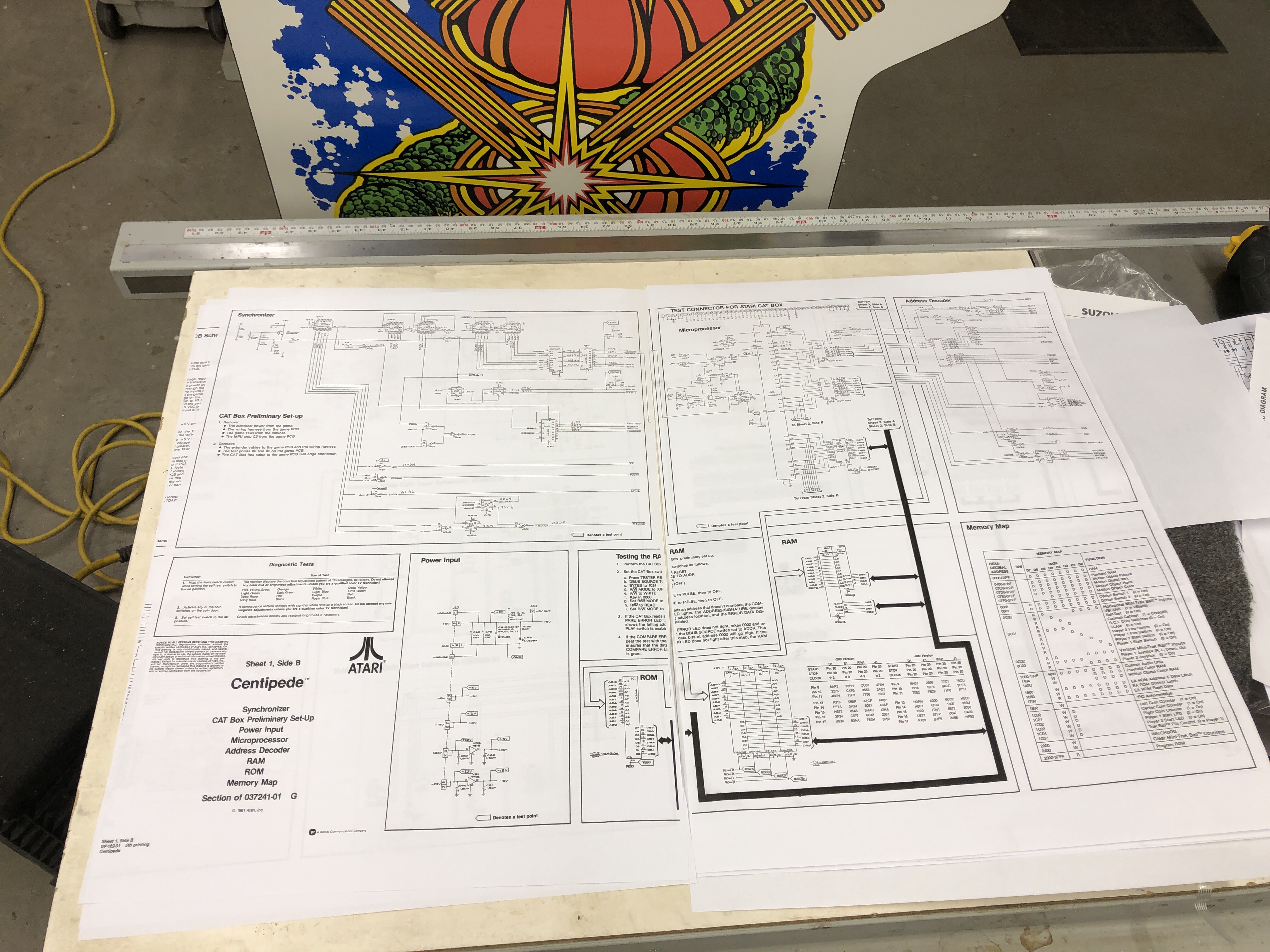
Certainly this isn’t a requirement. Have it nearby on a laptop and have at it. Large print drawings makes it easier for me and I can write on it. The schematic will tell you all of the voltages the board expects. On this one – it has a power input section to provide the specific details.
STEP 1: Visual inspection
Take an inventory of the board and look at all of the chips, look for obvious missing parts. My dead PCB was missing the Pokey chip (I was told this was the case). Other parts could be worn or broken off too. Being able to compare to a working board is helpful. Some boards have empty sockets by design..
The other thing I did was remove chips that were socketed, cleaned the pins, sprayed a little Deoxit and reinserted them.


Find a full is of items I use for repairs and restorations on my Lakeside Arcade – Amazon Store page
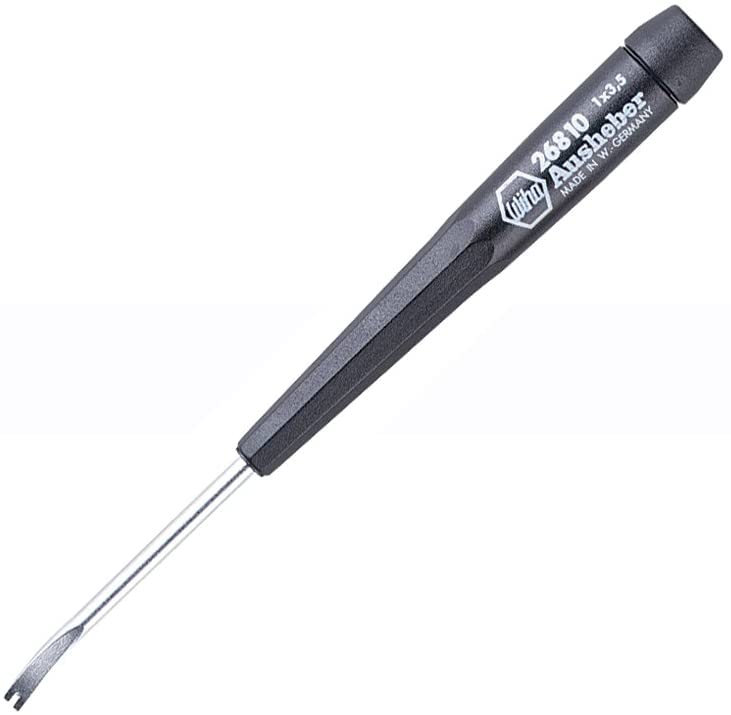
The fiberglass pen works great – it really cleans up the contact areas of the card edge connector and the legs of any chips. Shine up the edges and pins like using a pencil eraser. The chip lifter is what I would consider essential. I have 3 of them so I’m never hunting for it. Lifts chips and is a lot less likely to harm the PCB vs. a screwdriver or anything else. It has enough shape and strength to just get under the edge of a chip and pry it up just a little. Pry a little at a time from each side and be careful not to bend the legs – no need to rush on any chips here. You want to chip to come straight up as much as possible, not tip out and bend the legs. Once the chip is out, I use the pen to buff up the legs inside and out.
Finally I squirt a little Deoxit on the pins and the socket and reseat the chip. Plenty of videos exist on extraction and reseating. If you’ve never done it.. Don’t practice on expensive boards.. break old crappy ones until you get a good feel for it.
I cleaned and reseated all of the removable chips on my dead PCB.
STEP 2: Verify that the EPROM chips are good. The EPROMS are the software that is the game. This part requires some investment. I purchased the GQ-4X4 EPROM Programmer
Centipede has 6 EPROMs on the board. I’d already found one bad one. But without verifying each EPROM individually – you will never really know if you have a software issue. The EPROM programmer and reader is a bit glitchy, it locked up a couple times, but for the most part – if its acting weird – just exit the program – unplug the reader and start over. It worked quite well overall. Do get a 9V power supply for burning replacement EPROMs. USB *MAY* have enough power to do it, a power supply will absolutely do it.
There are a few sites out there to test the EPROMS – This one worked great for me.
Arcade Rom IDentification Tool
Read the EPROM, save it to your desktop and drag/drop it onto the webpage. It will either verify the EPROM or tell you it has no idea what it is (meaning bad program).
Perfect! I found 2 additional bad EPROMS. Now to burn new ones…
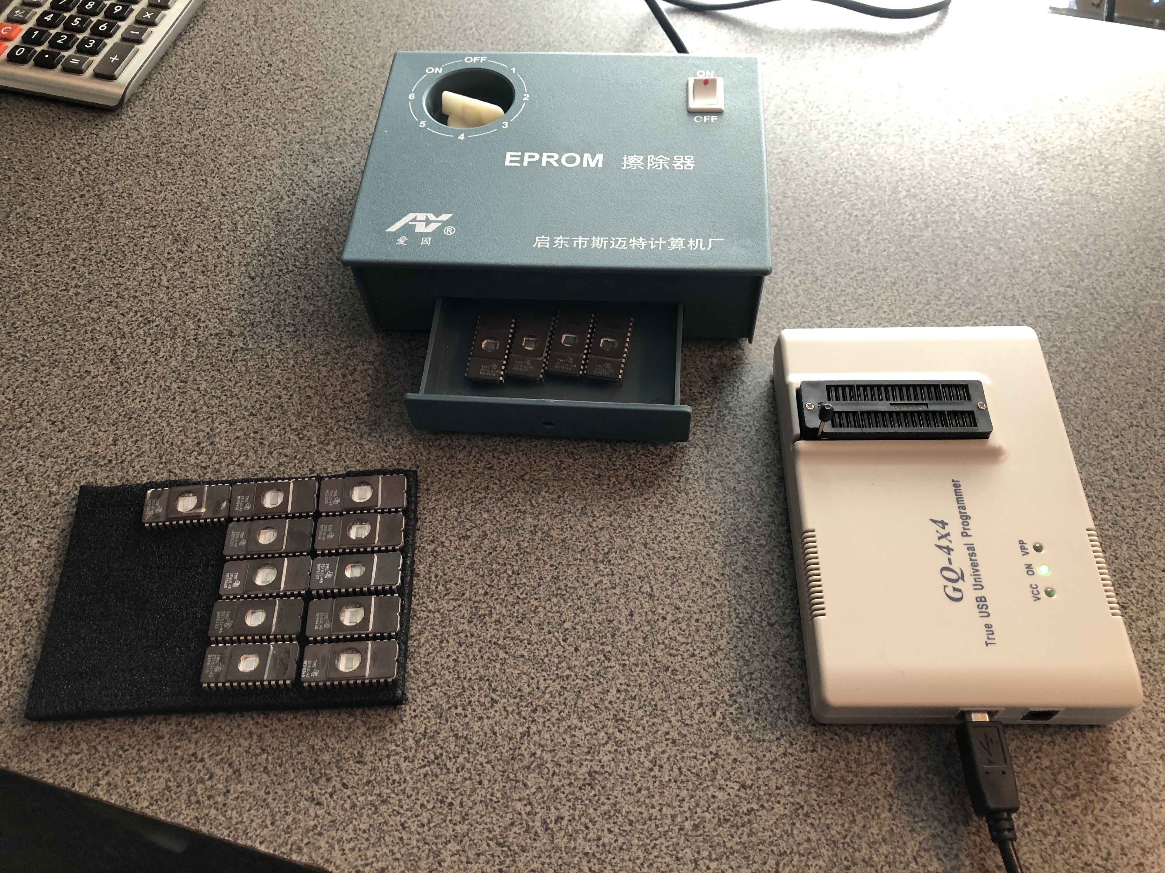
I picked up this inexpensive EPROM eraser and matching EPROMS off EBAY. The Centipede EPROMS erase with UV. This little $20 eraser is pretty crappy from a quality point of view. The knob is supposed to be a timer – its crap. I opened the box spliced it out of the circuit. There is a small UV bulb inside – the on/off switch now just turns it on/off.
Notice the position in the drawer of the EPROMS. My eBay EPROMS were not all erased. I cleaned the windows with acetone and filled the drawer. 45 minutes under the light and only some of them erased.. But I figured it out. You really need to line them up like this so that the windows sit DIRECTLY BELOW the UV light inside the drawer. Once I did this I got a good erase on all of them every time.
On the EPROM programmer screen in Windows – put a blank EPROM in, test it for being blank. I would test 2-3 times to be sure.. Like I said – it can be a little glitchy.
Once verified blank – get the correct EPROM bin files. I used my MAME zip files and extracted the ones I needed. Each MAME file will have the ROM number in its file name, etc.. Write it to the blank EPROM and verify it 2-3 times.
Once you verify and check all of the EPROMS – you know with certainty the PCB has the correct software. Cover the little UV windows with a label and the EPROM number.
STEP 3:
Before plugging the PCB into a power supply – check for shorts to ground from the power test points on the board. Using the ohms’s setting, connect to negative and check for low (or no ohms) on all of the power test points on the board. If a regulator IC is dead and shorted to ground – you want to know before connecting to your power supply and potentially ruining it.. As long as you are not showing an shorts…
Now plug the PCB into your good cabinet!
Validate you have all of the correct voltages on the PCB. The 5v+ should be very accurate (i.e. within .1v or so +/-) on the PCB. There will be other voltages all over the board.
My original Centipede had these:
PCB Test Points
Test Point Actual Voltage
+5v +5.063v
-5v 0.569v
+15v 0.001v
-15v -15.12v
+22v +24.72v (unregulated)
-22v -24.93v (unregulated)
-30v -14.00v
I documented the repairs in my restoration thread: PCB Repair
The main point is to check and repair any of the voltage regulators first. Each test point is going to lead back to a regulator or something on the board creating that voltage.
My dead PCB had all of the correct voltages (I was surprised).
After plugging it in and seeing nothing on the screen, I happened to touch one of the EPROM chips and it was very hot. I’m going to bring the laser thermometer to the shop and check the boards with it moving forward.. My bet is they all should be pretty close temperature wise – but none should be HOT! Bad EPROM chip identified.
STEP 4:
Verify the RAM self test is actually running on the PCB you are repairing. Many boards have a mechanism to beep a number of times to map to a bad chip. Its not always apparent that this is actually happening.
On Centipede you need to disable the watchdog circuit (if its triggering) to get the memory test to run.
I know on Space Invaders it doesn’t exist. You need to burn a custom ROM to run the tests for you..
Once all bad RAM/ROM are cleared – you have a better chance at finding other issues.
So Far….
- We have visually inspected the board – replace obvious broken or missing chips
- Look for bad solder joints, disconnected jumper wires, etc.
- Cleaned, Deoxit’d and reseated all of the socketed chips
- Cleaned, Deoxit’d the card edge connectors
- Plugged the board into a working machine
- Checked all of the chips for excessive heat (finger, laser thermometer)
- Checked all of the voltage test points per the schematic
- Replaced voltage regulators, etc.
- Get all of the voltages correct now.
- Verified all ROM chips programming and replaced any failed chips.
- Verify RAM self test
These steps alone fixed one of my two dead Centipede PCB’s. My other dead Centipede PCB will require additional diagnostics..
This is the tip of the iceberg – watching PCB repair videos and just reading up on the process will tell you if its something you really want to dig into..
