

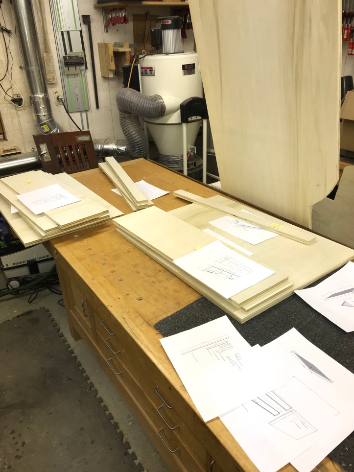
My final revisions to the Sketchup plans were focused on trying to eliminate some oddball measurements where I could and creating a design that I could build a cabinet that could be disassembled if needed using threaded inserts, etc.
I made a rookie mistake and didn’t take that final step of creating a cutlist style layout in sketchup. Had I done this – I would have easily fit both side panels on a single sheet of plywood.. I trimmed the height first and ended up needing to cut into a second sheet. DUH!
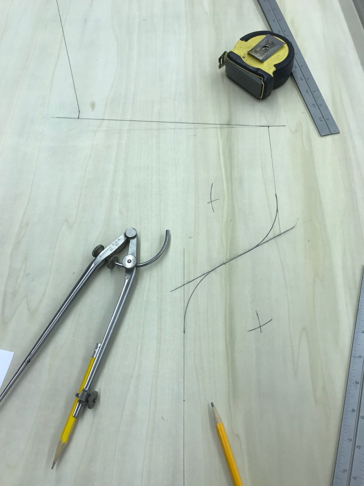
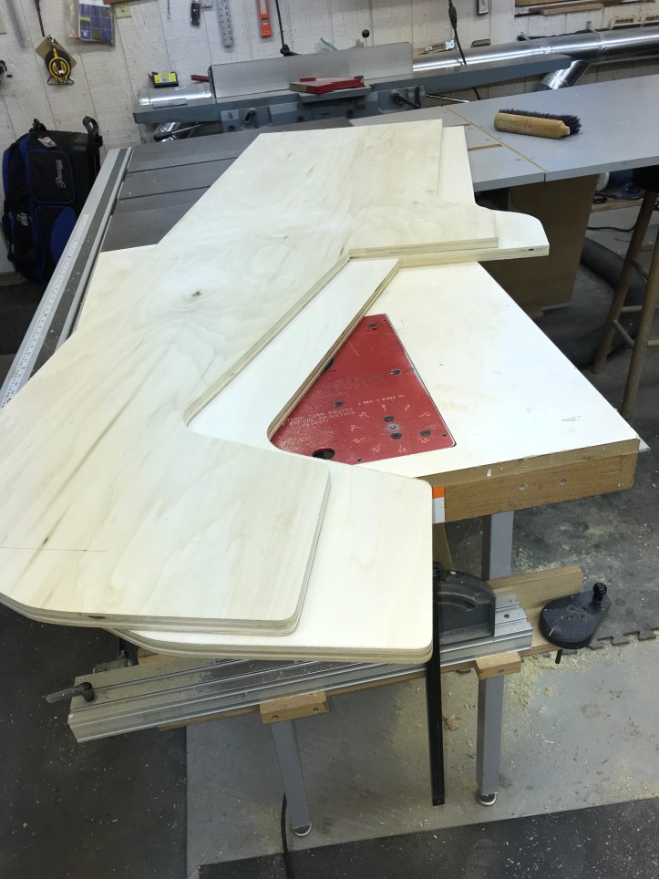
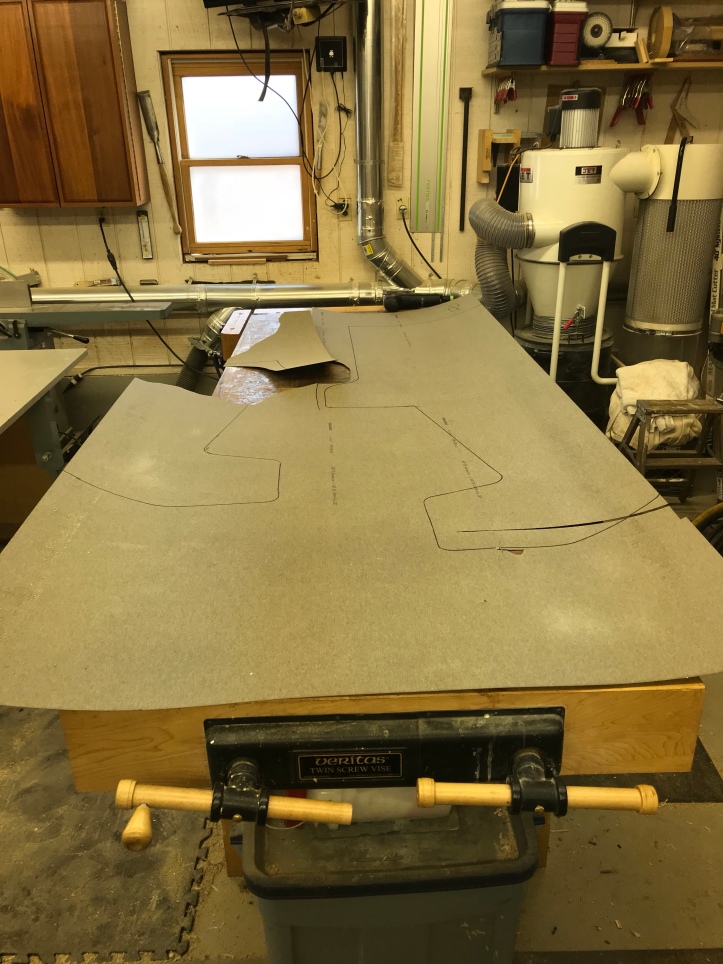
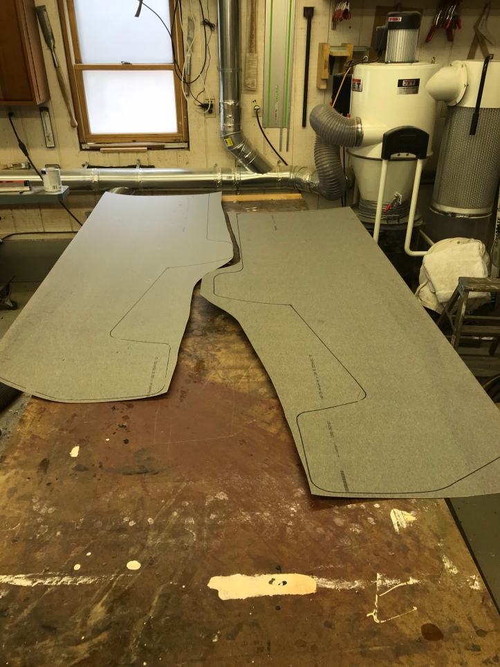
Here is a side panel all set up – Sketchup measurements made it all simple to do and even though I had specific angles for the control panel and screen angle – I was able to plot points and just connect dots to make it all work. I did double check them however..
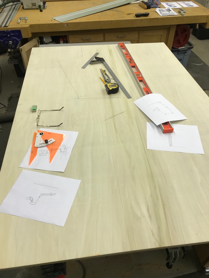
My plans provided radius etc…
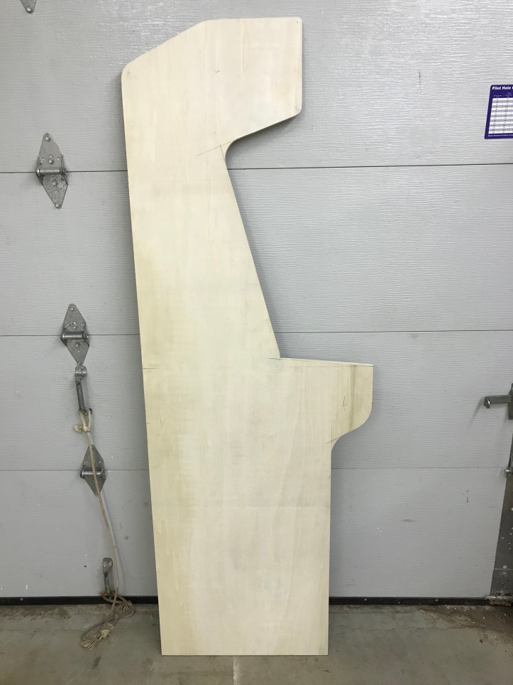
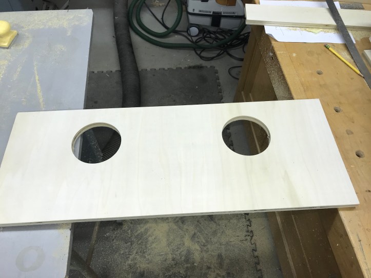
First panel completed. I used the plunge saw for the majority of the straight cuts and the jigsaw to get close to the curves. Then I cleaned them all up to fair lines with a drum sander, rasp and block plane to get it as clean as possible.
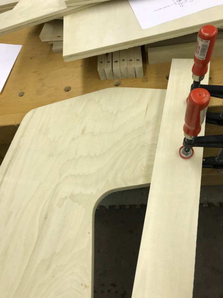
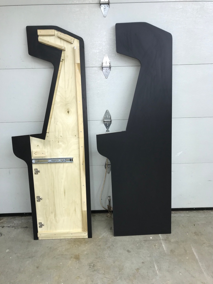
Making the second panel is ultra-simple. Trace the original in pencil, cut outside the line with a jigsaw and double stick tape them together. Using a pattern bit (spiral down cut is best for this) – just duplicate it with a router. Less than 10 minutes on the second panel.
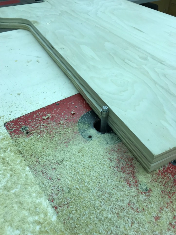
Quick work on second panel.
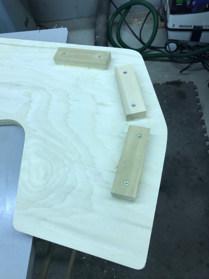
Next is lining up blocking for the marquee – using a guide blocks is much more accurate than a pencil line and simplifies the layouts.
Cabinet top blocking in place
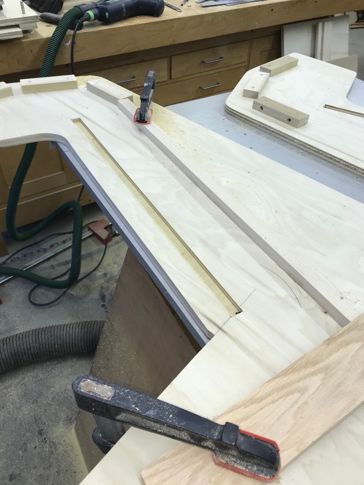
I want a clean bezel to side panel joint – using the plunge router and guide fence let me add this detail.

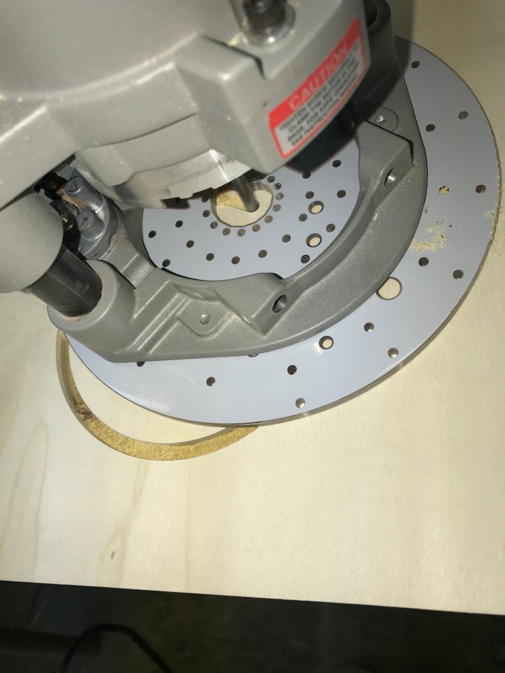
I see many questions on the forums on cutting large circles. The best way is to get the Jasper circle jigs for your router and cut them that way.. It is a clean, simple cut and you can cut many size circles. Big hole saws are clumsy and expensive by comparison. The have a small hole and large hole version.. Worth every penny.
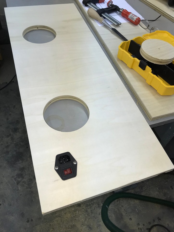
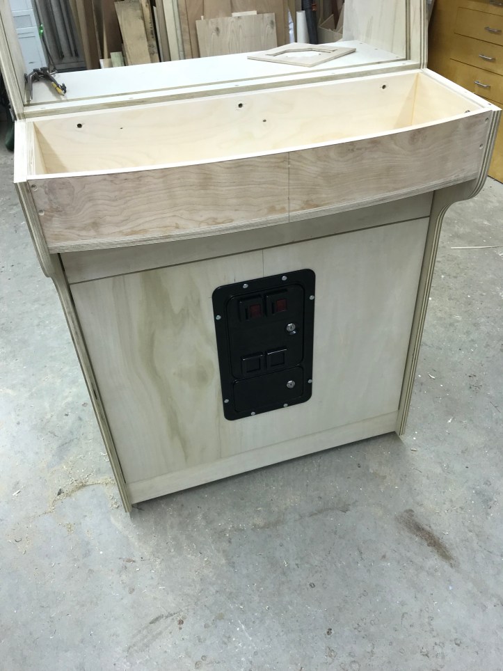
Power jack added
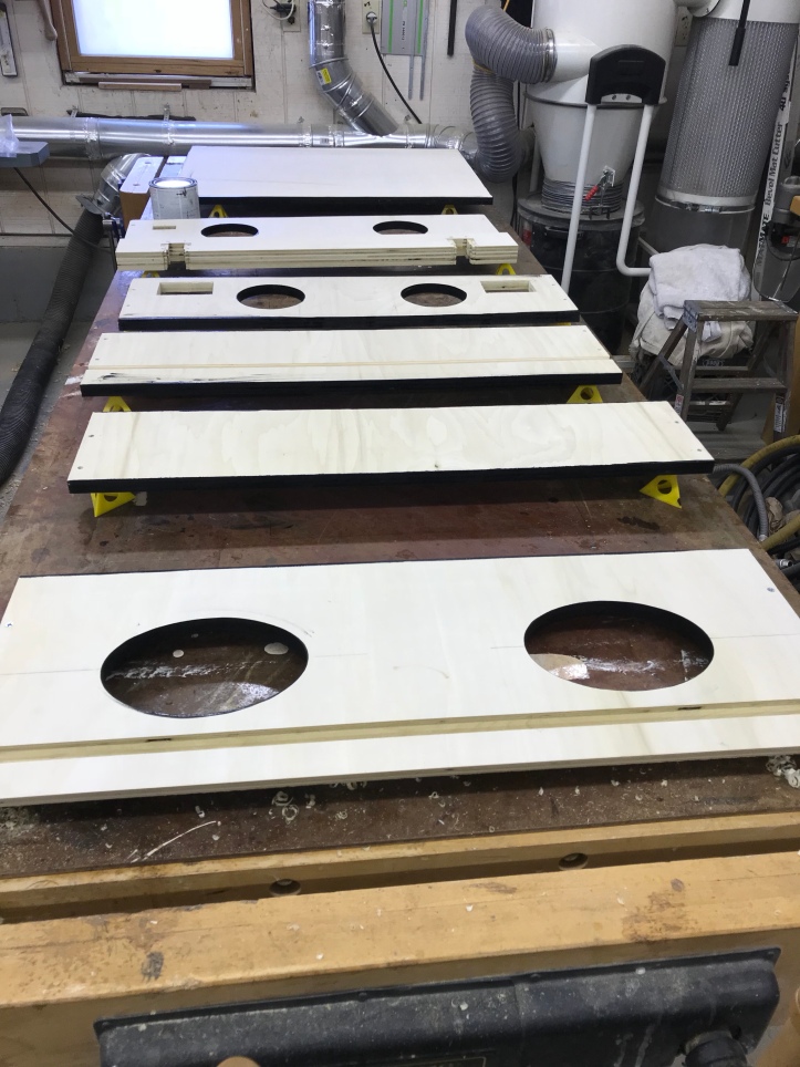
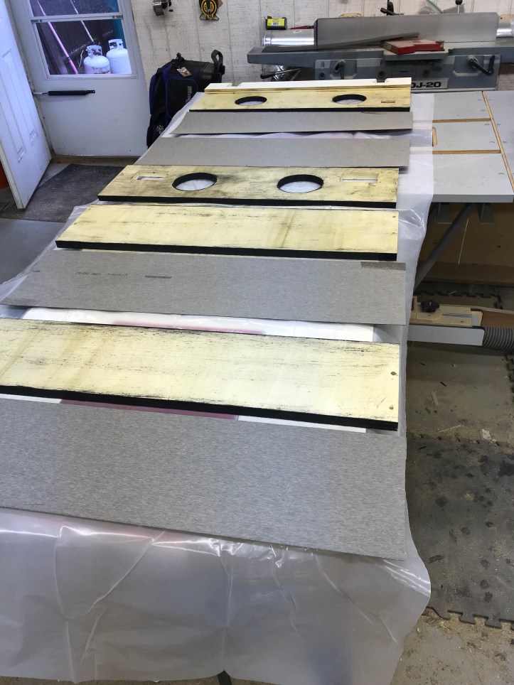
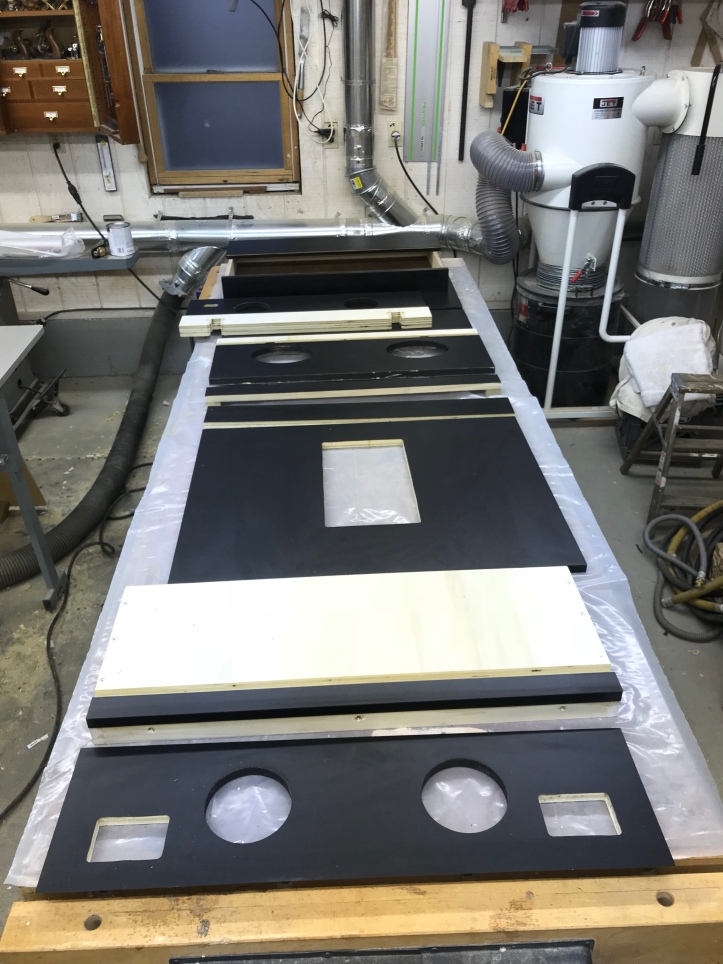
Part of my philosophy is to create a ‘kit’. Get all of the panel blanks built up and labeled.. then customize them as needed..
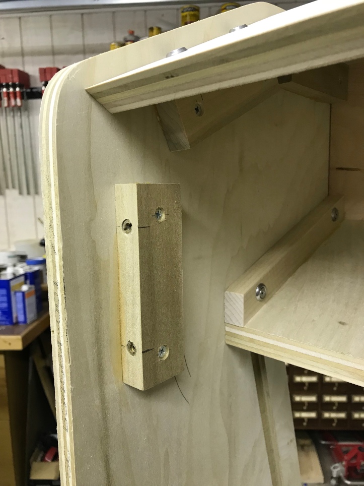
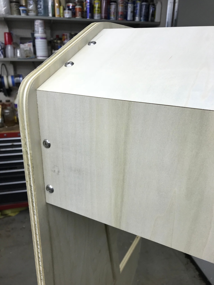
Here are the top panels getting fit into place. The are going into threaded inserts that are in blocks glued to the side panels..
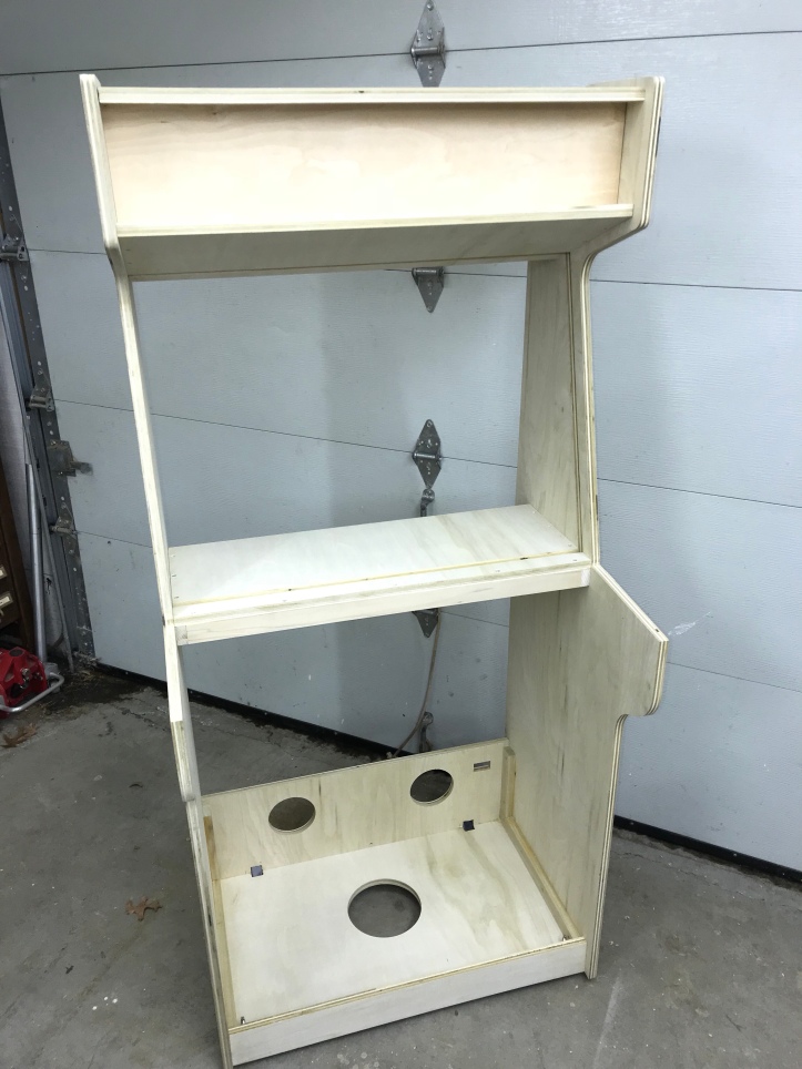
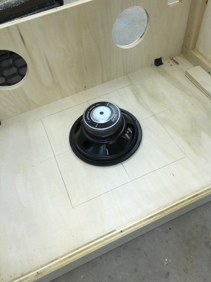
Bottom panels with a vent holes in the rear and a 7″ hole for a subwoofer. My cab will have jukebox mode and the amp should have enough smarts to break out a little bit of bass (I hope!)
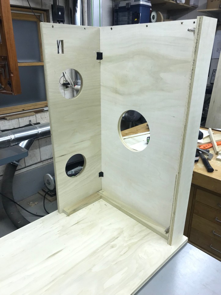
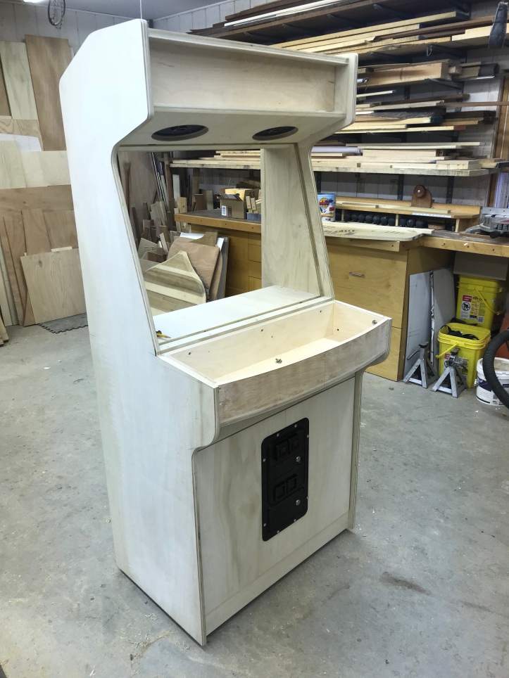
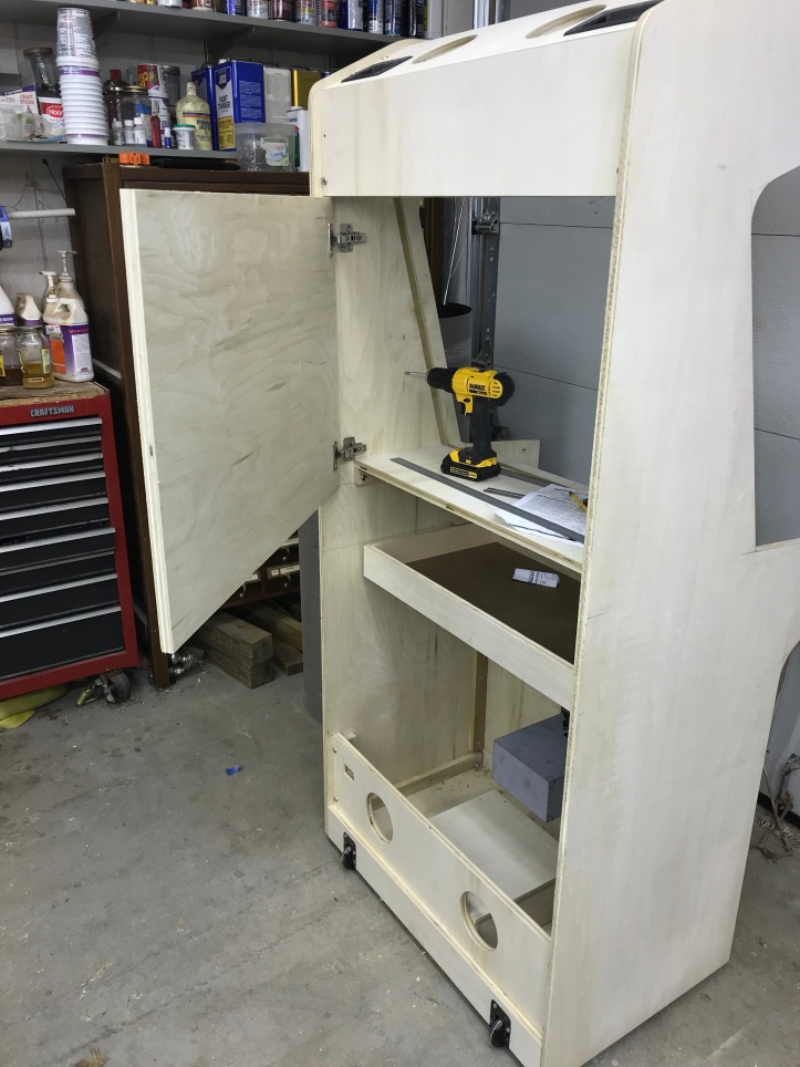
First assembly with enough parts to make it cabinet shaped.
It is a bit wobbly at this point – I think a few more components and the CP design will stiffen it up nicely once it is all build up.
Rear panel blocking with threaded inserts.
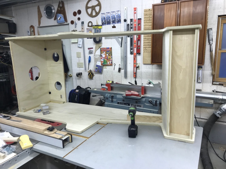
I added the upper back panel in place. Its not necessary to have a nice tight fitting miter joint.. but it certainly looks nice.
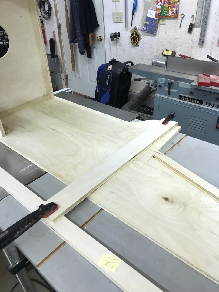
The marquee shelf went together quickly. I’m using a 15 deg tilt for the monitor.
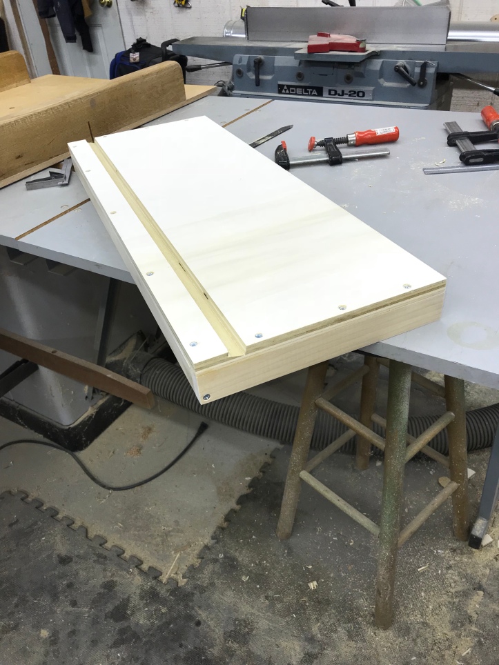
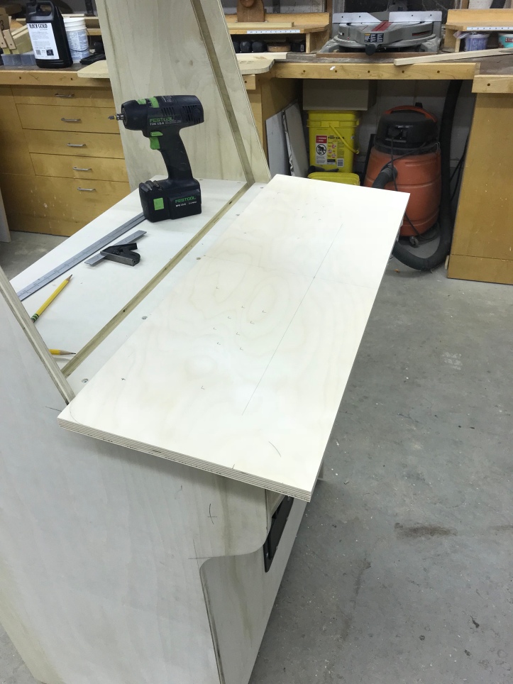
I’ve been using my table saw as a bench. The bench is covered with other parts. The easy way to line up the shelf is to clamp a straight edge in place..
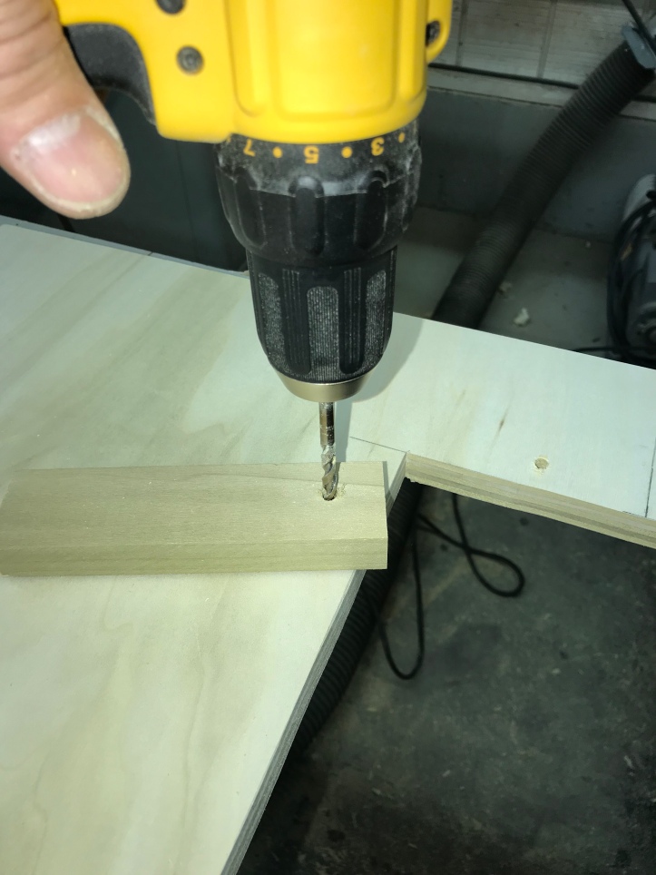
Here are the threaded inserts.. Best way to make the holes is to use a 3/8″ Forstner bit to drill a clean hole. Then screw them in..
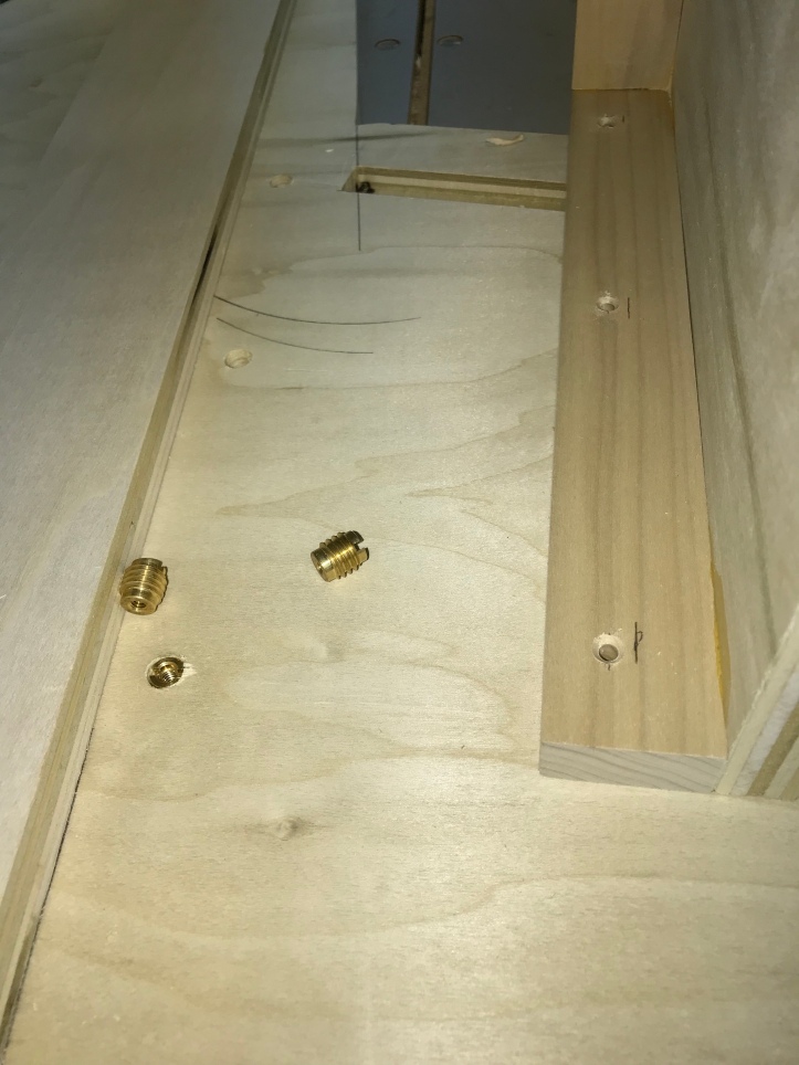
10-24 Machine screws with finish washers hold the shelf in place. I drilled the holes in the shelf at 1/4″ to allow for some adjustment of the shelf. Its nearly impossible to line the holes up perfectly.
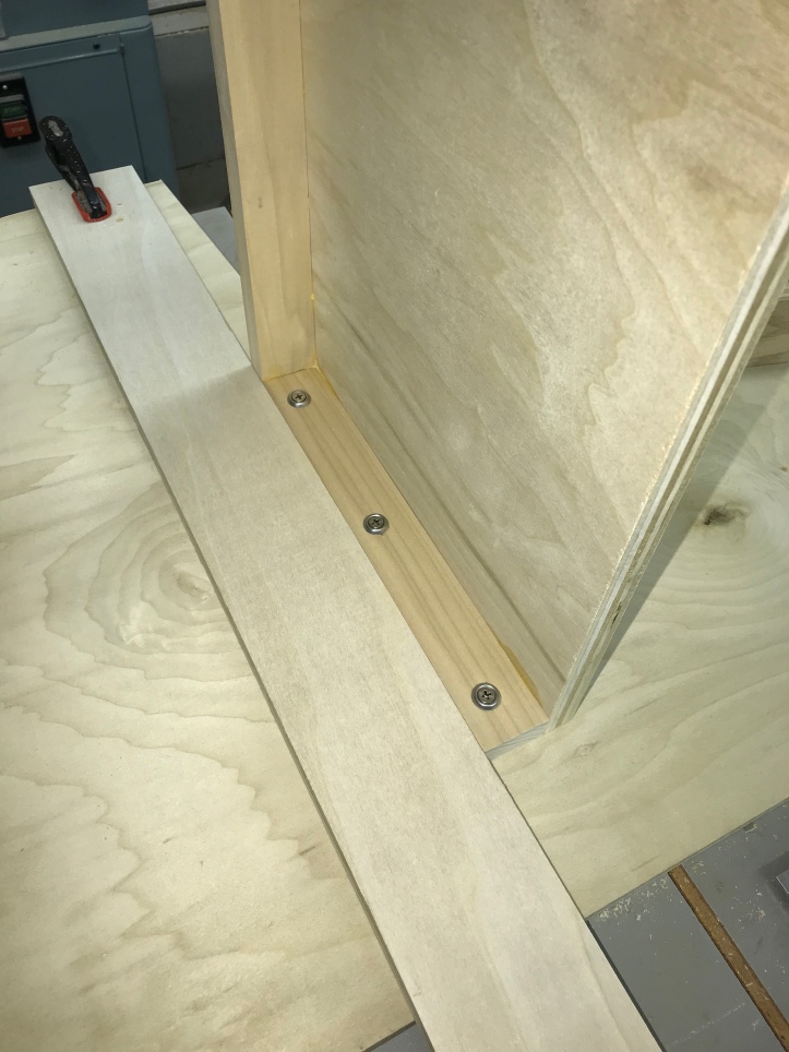
This stiffened it up a little bit..
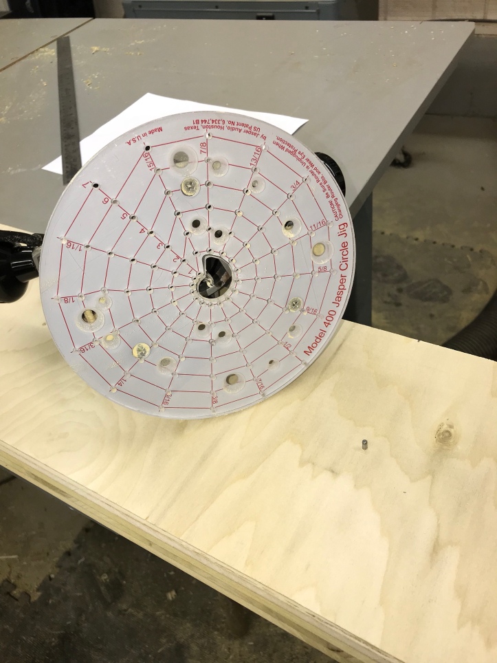
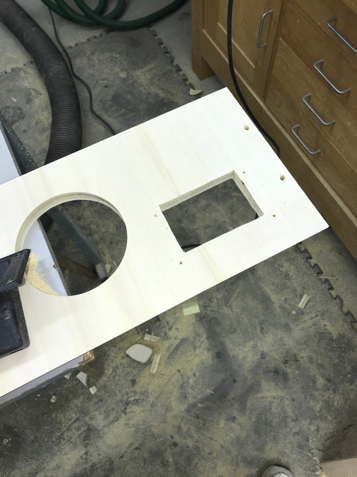
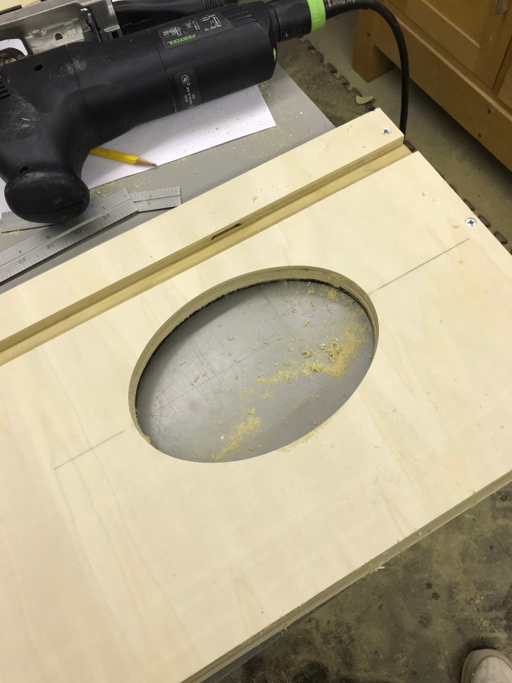
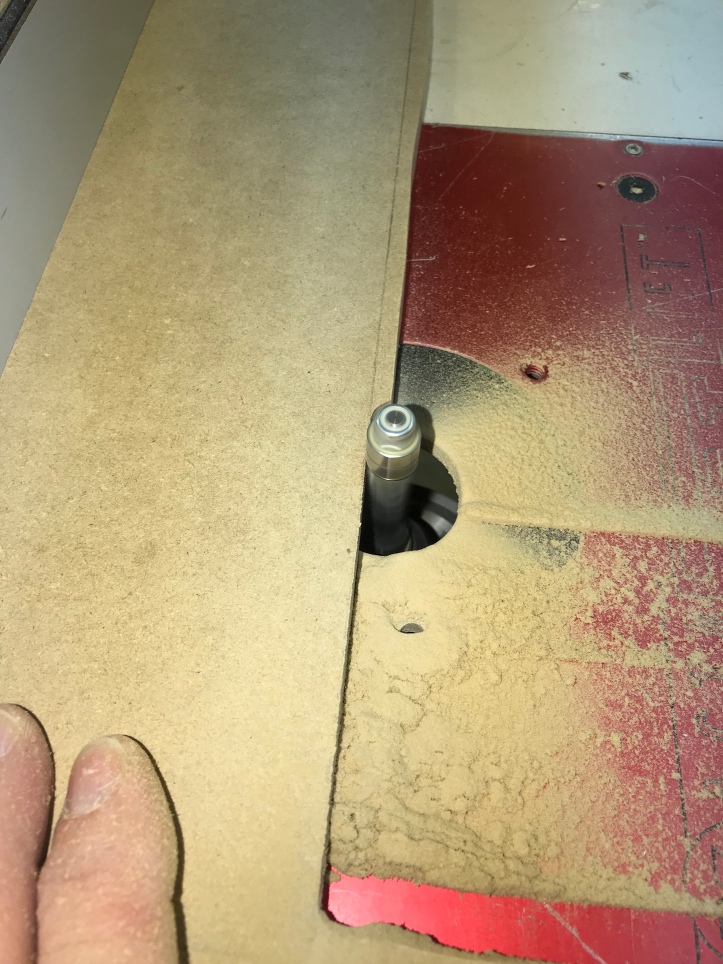
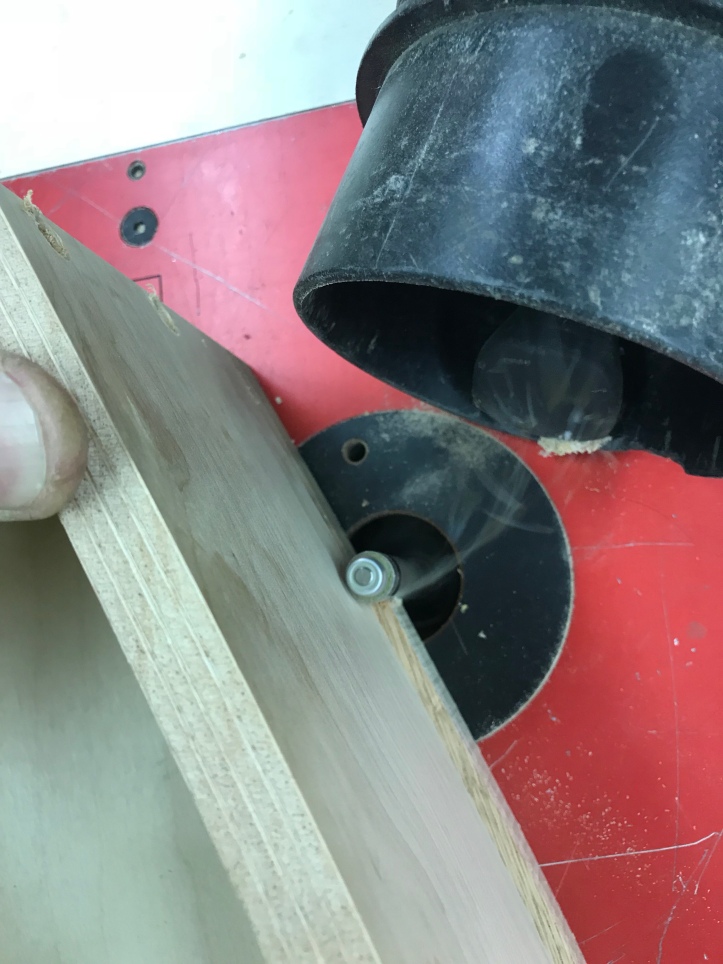
Tonight I added more holes to the cabinet. Below is a closeup of the hole jib for the router. It will cut any size hole in 1/16″ increments up from 1″. Drill a 1/8″ hole and insert the pivot pin…
To cut the hole – align the pin on the jig to the correct diameter – plunge and cut the hole.
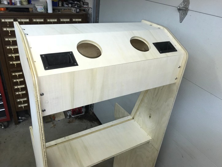
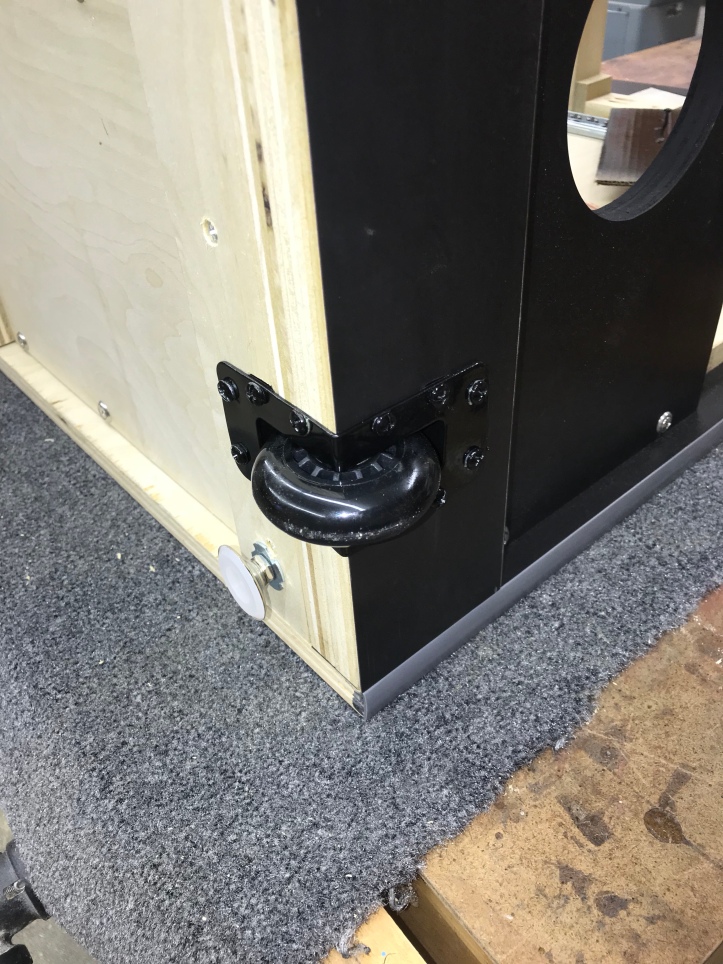
I saw a cabinet that had hand holds for tilting and rolling the case. They cost under $10 and I figured it was a simple addition.
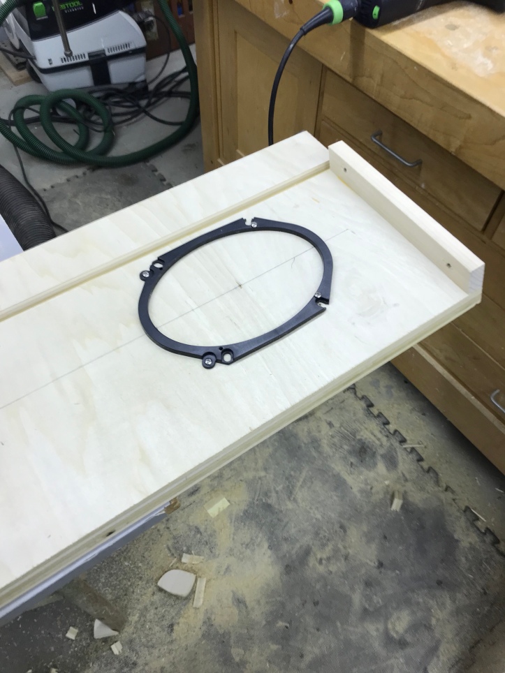
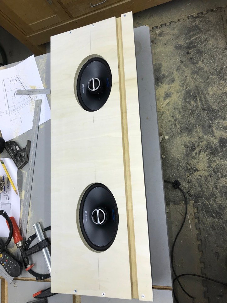
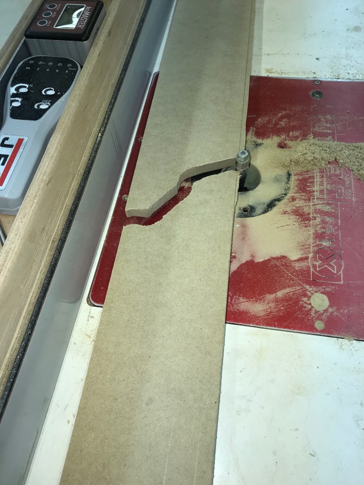
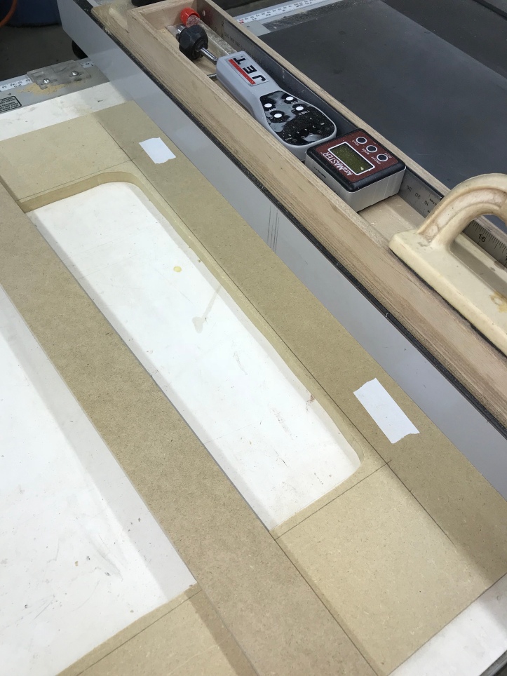
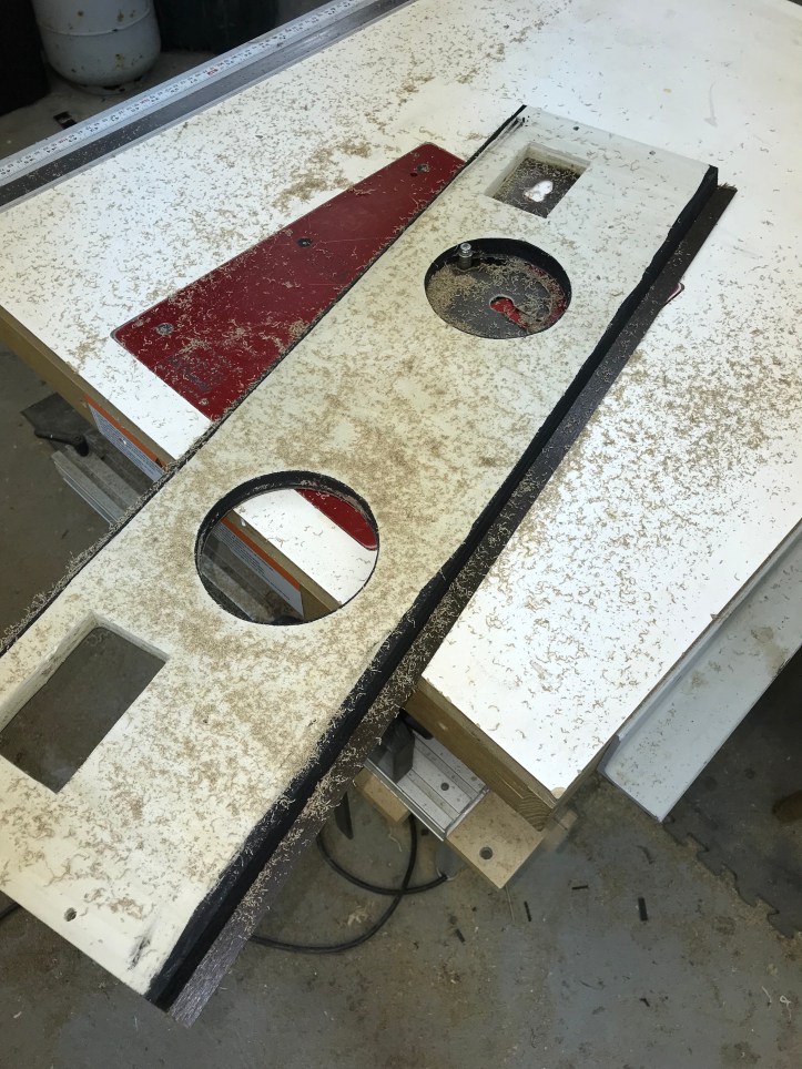
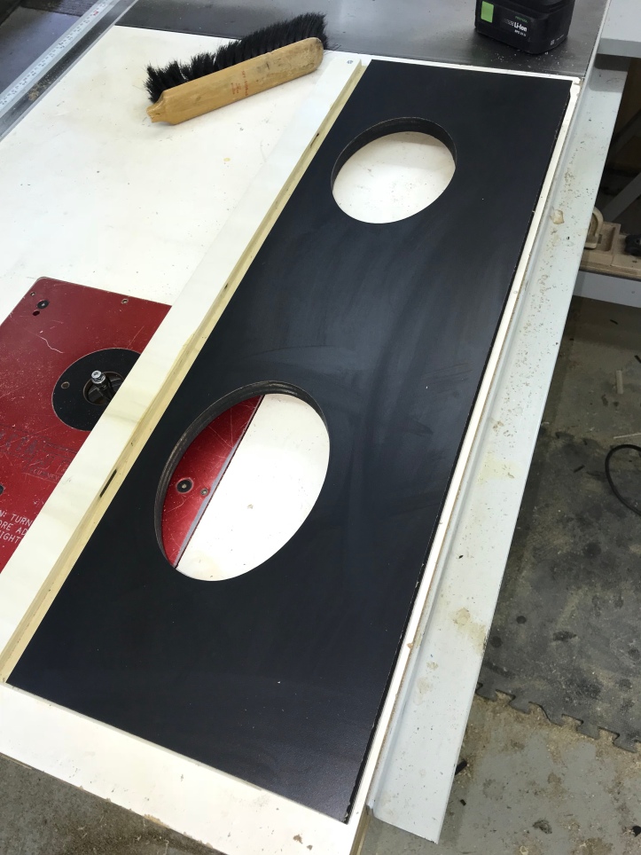
The speakers I chose came with a gift! They had the perfect sized trim rings that I could use as a template to cut out the speaker holes. I aligned them per my plans
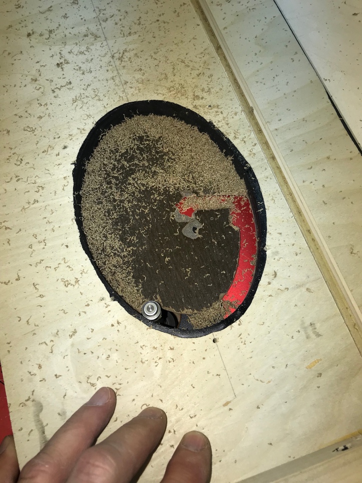
Before cutting them out on the router table – I removed the center to make less work for the router bit.
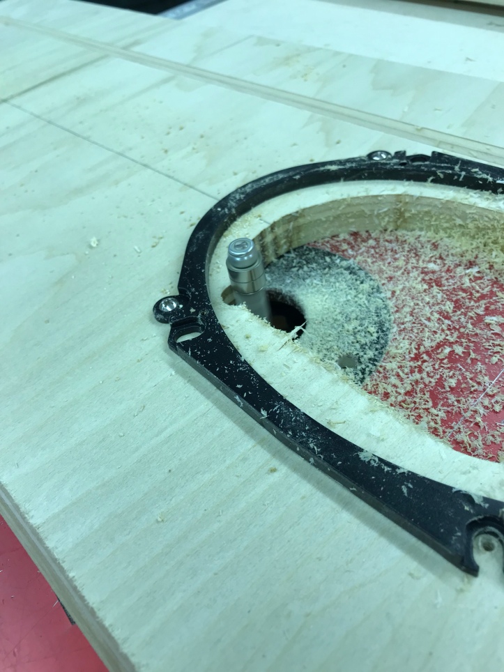
Perfect oval ..
I still need to decide if I will use grills or speaker fabric over the whole panel. These are very middle of the road speakers ($54) – I’m certain they will play Mame games just fine. If I have an ok background music jukebox mode, that will be an added bonus. Or maybe some more modern games with bigger sound at some point.
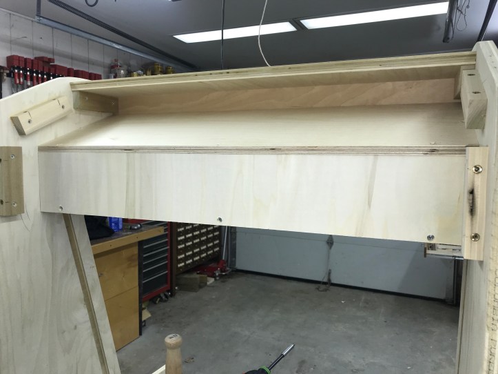
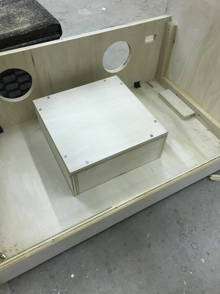
My plan all along was to box & insulate the speakers. Here I added rails and a back panel to enclose the top coaxial speakers.
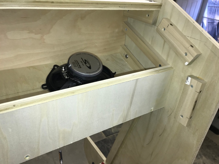
A box within a box.
Same plan for the subwoofer (also quite inexpensive)
Simple 12 x 12 x 4 box over it. They will get wired and insulated during final assembly.
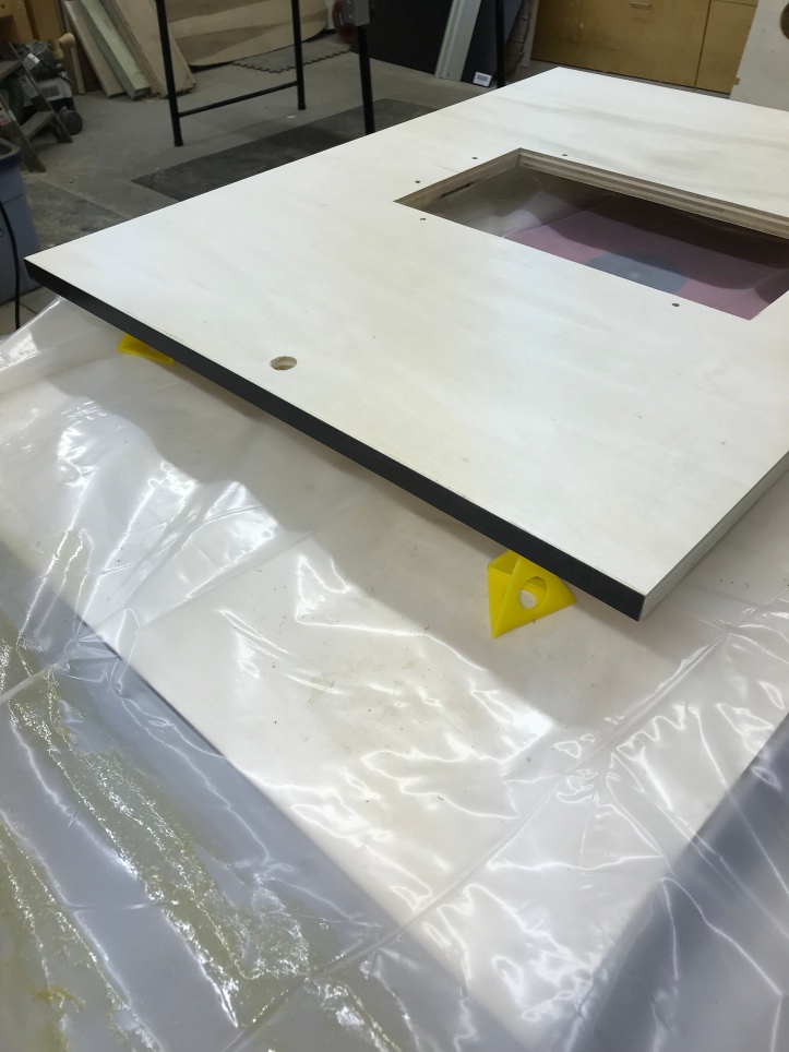
My next task was to create a bezel for the monitor (32″ LCD).. I was able to gently pop off the bezel for the monitor itself. This will allow it to mate up flush to the 1/2″ MDF I’m using in the cabinet.
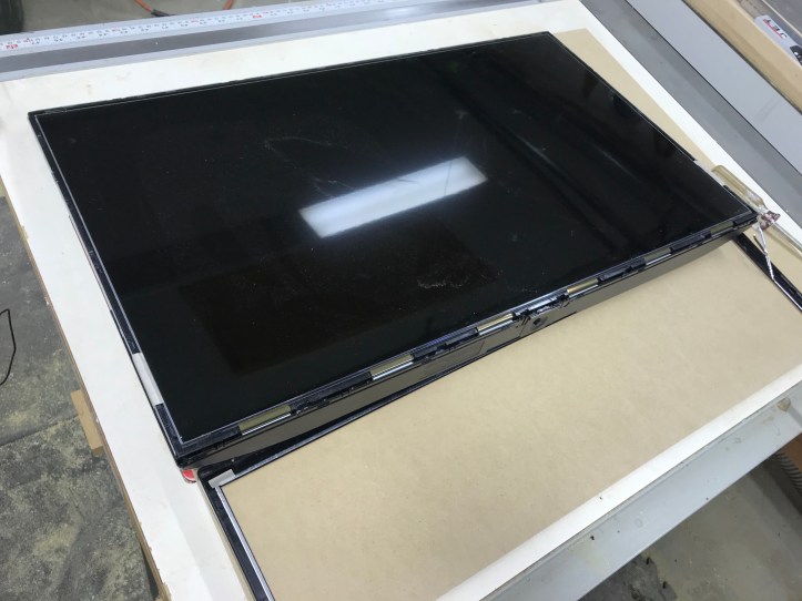
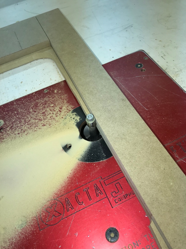
The plan was simple – draw the line on the MDF blank that I needed – precut with a jig saw – the finish cutting on the router table using a fence to get it straight.
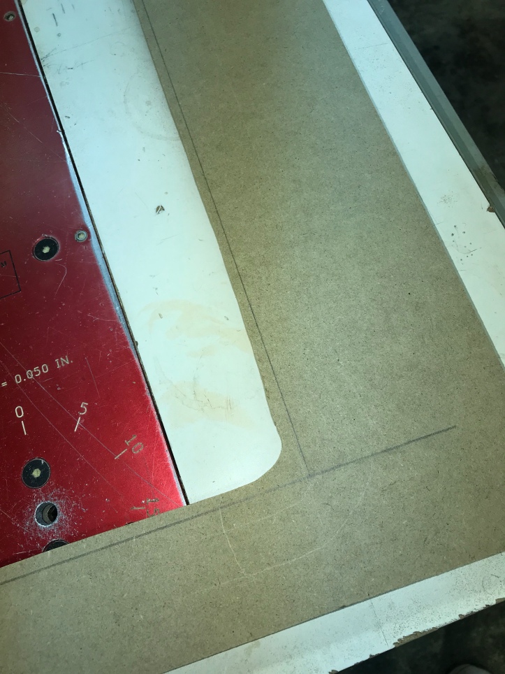
Here you see the fence on the left – cutting a straight line.. and…
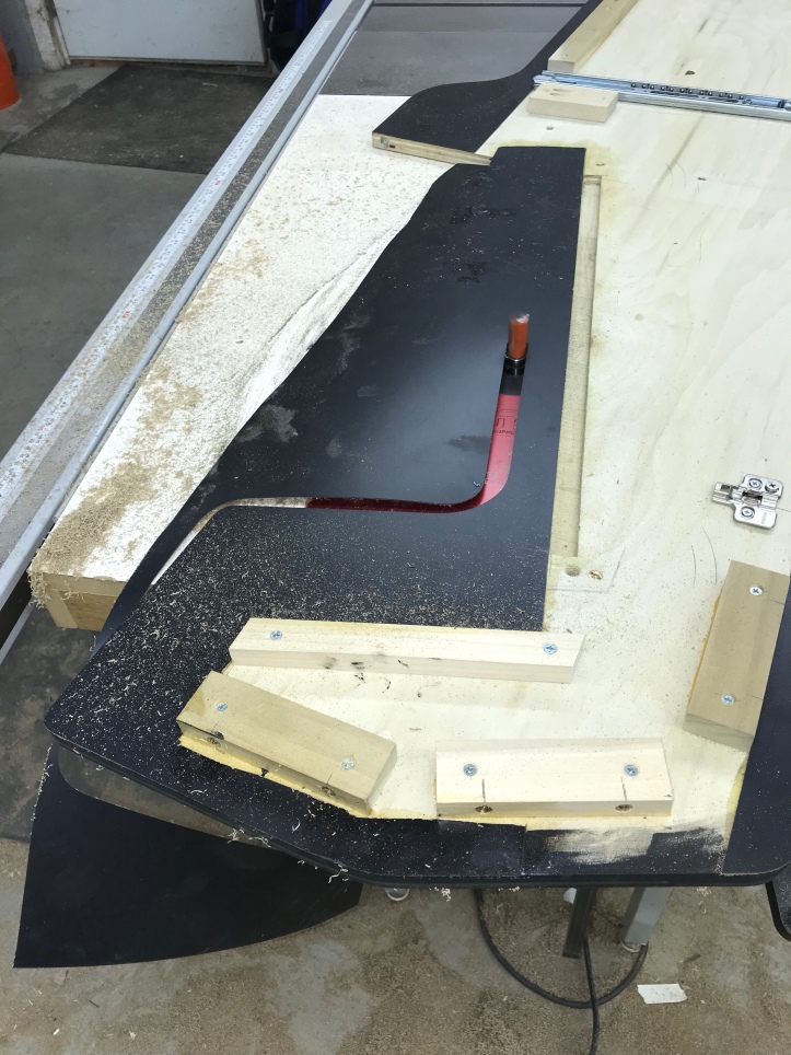
The router bit grabbed because I was going against the cutter direction and pulled right through the bezel… ok .. Now I’ll do it the right way.. after a trip to the Depot to buy another 2x4x1/2″ MDF.
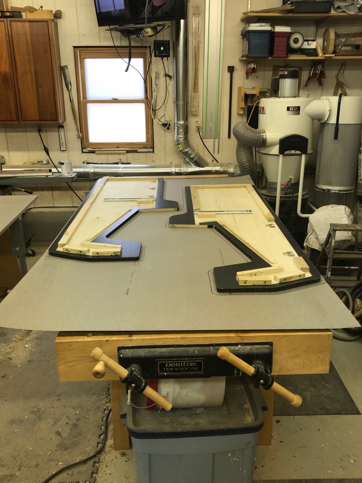
This time I double stick taped guide blocks to the (new) cutout.
Then used the pattern bit to follow the guide to get my opening..
Since I was able to get the bezel off of the LCD – I wanted my bezel to have a little bit of angle on the opening.. I had a 14deg dovetail bit.
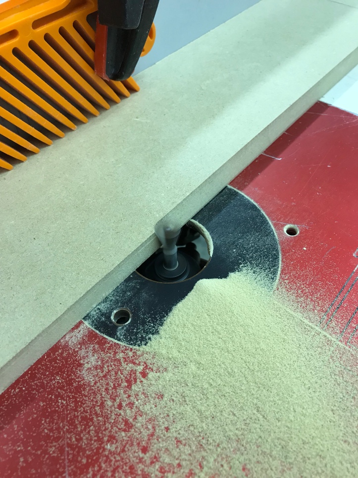
I’m doing the exact thing that caused the first MDF failure – using the fence and trying not to accidentally pull the work into the bit.. However – I’m taking off much less material with the dovetail bit. I’m making sure the piece can’t lift with the feather board.. and.. I’m routing in the proper direction with the bit. I started in a corner, started the router and lowered the bit down to get the profile I wanted.
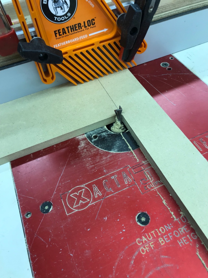
I was very careful to keep it tight against the fence and create the profile.
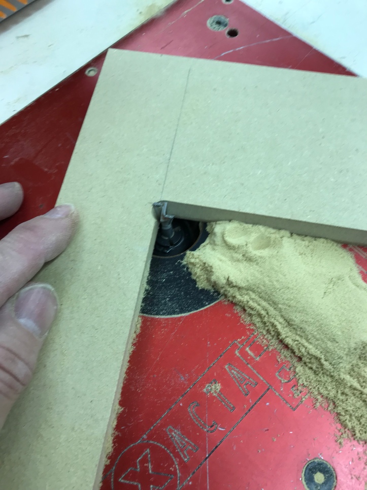
Then you have to stop in the corner, turn the router off, move the fence, turn the piece to the new side against the fence and repeat for all 4 sides.
The color is off for some reason – I used some blocking and mounted the monitor directly to the bezel and connected the PC to it.. I’ll be painting it black and covering with a smoked tempered glass..

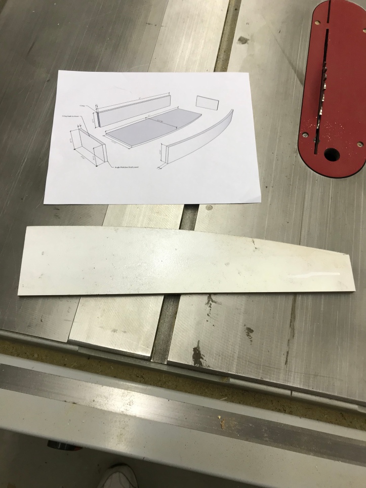
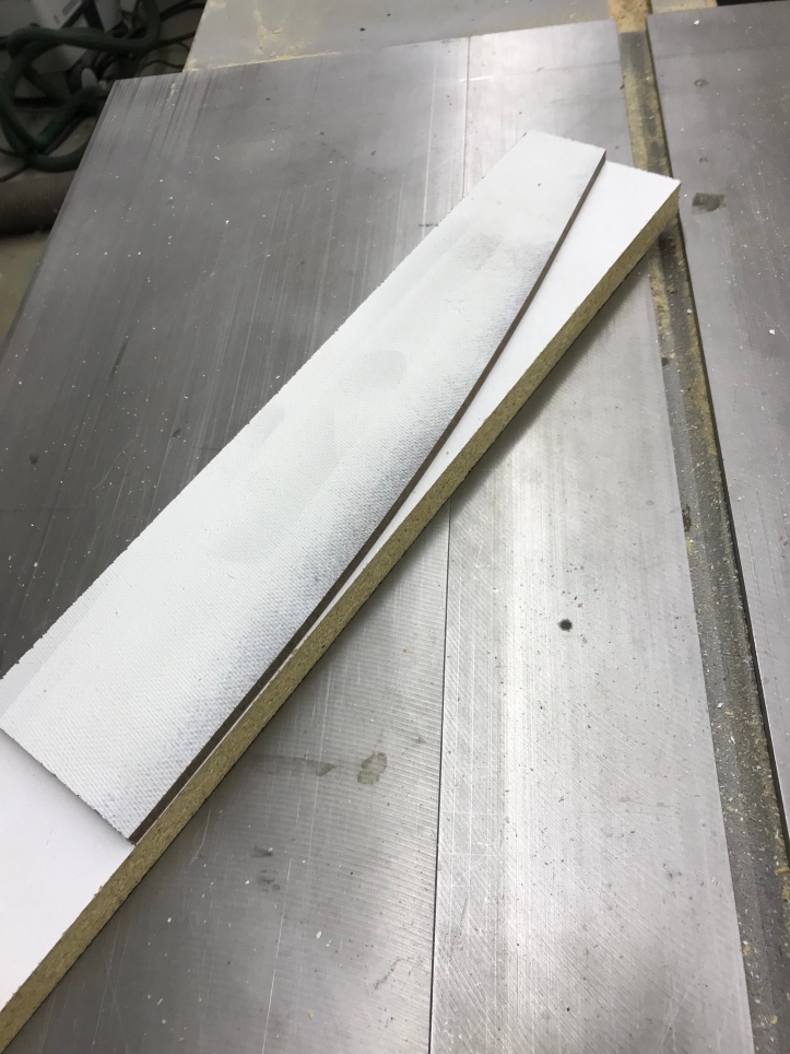
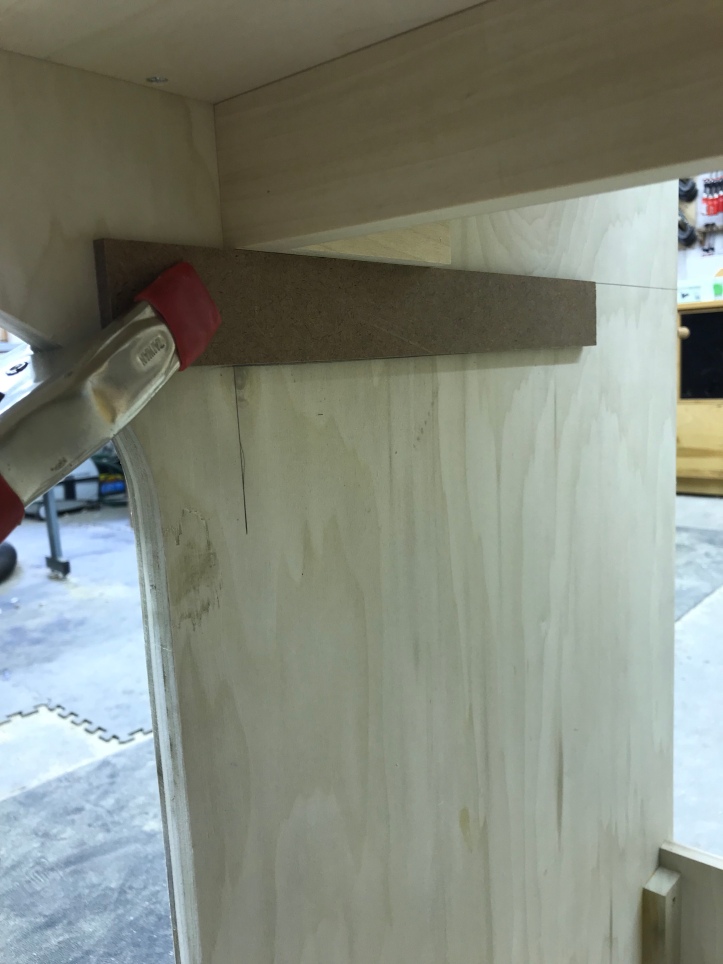
I’ve started working on the control panel box. It is a standard design except I wanted to add one nice (but unnecessary detail) of a curved front. The curve will match the leading edge of the CP itself. To be sure to make it symmetrical – I made a template out of 1/4″ hardboard scrap. It is one side of the curve of the inside of the front curved component. That piece will be made of laminated 1/8″ plywood.
First step is to make a form to bend the plywood on.. I have some scrap 3/4″ particle board. Double stick tape the pattern to the board aligned at the center..
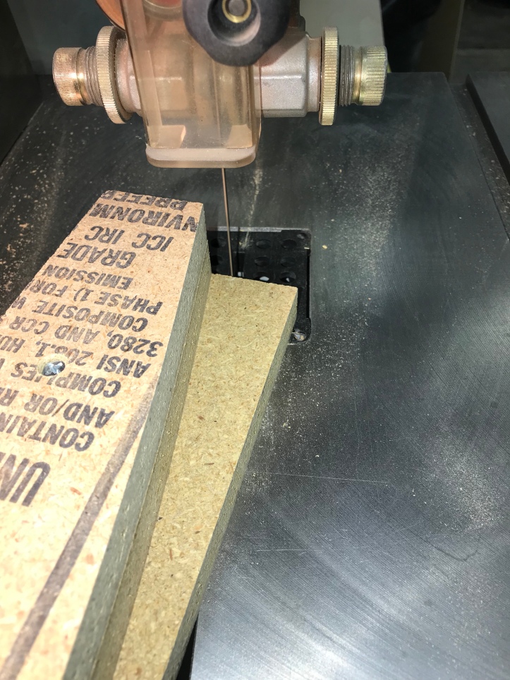
Then I trimmed close to the pattern with the band saw and finished the first side with the pattern bit at the router table.
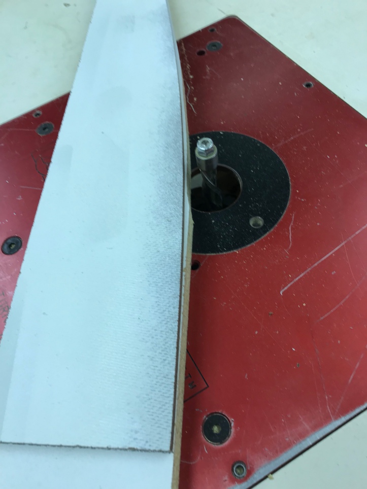
Next, flip the pattern and cut the opposite site – perfectly symmetrical pattern.
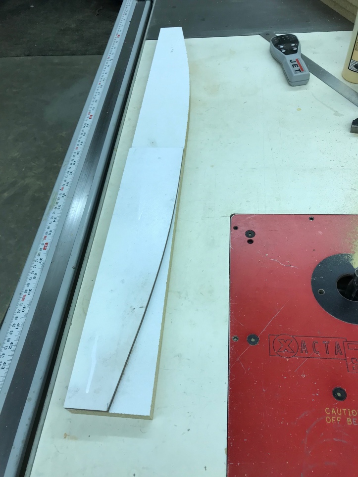
After the first one – the remainder are simple. Screw the next blank to the first pattern, trim close with the bandsaw (or jig saw). Then complete with the pattern bit on the router table.
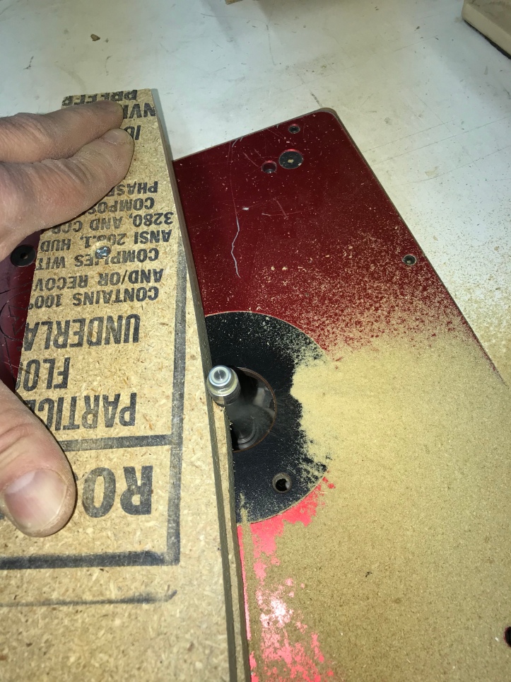
Repeat..
A stack of 6 gives me the form I need to mold the front panel.
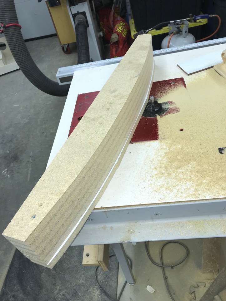
I double stick taped the form to an old laminated shelf. There is a center line on the form and on the four 1/8″ planks to help me line them all up. The plastic can be any type really.. best if duct tape sticks to it. I got as much of the setup staged as I could before gluing up the planks.
The whole purpose of this step is to make my own piece of curved plywood.
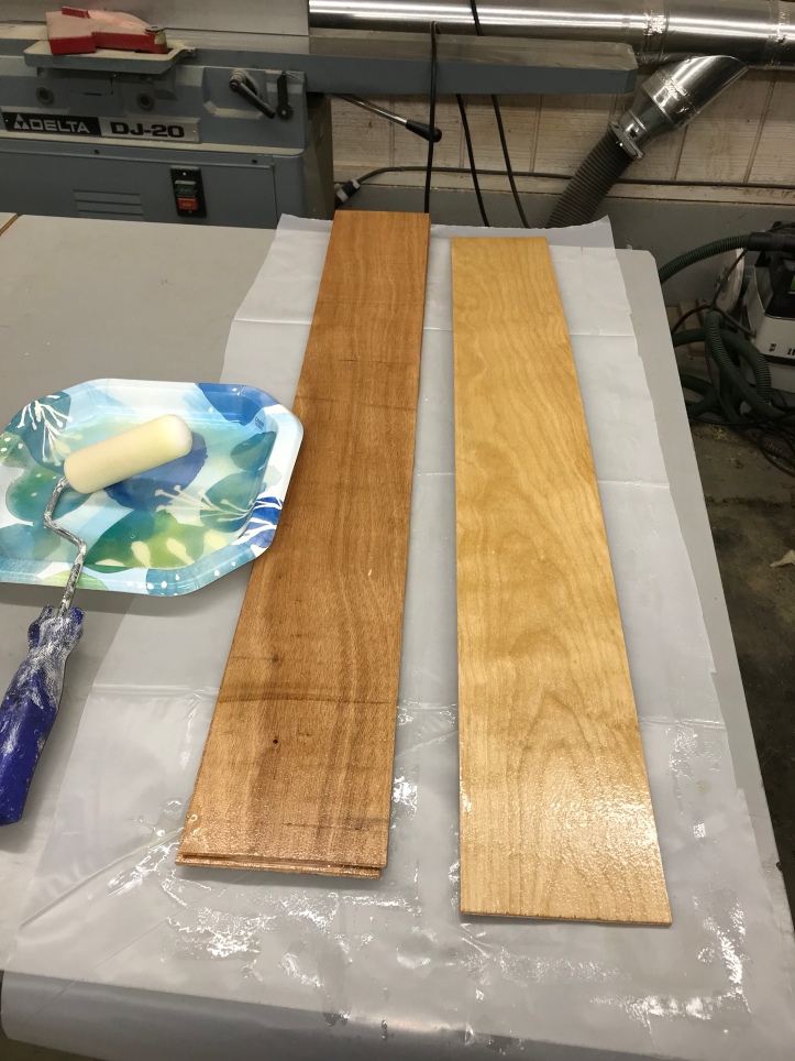
Here are the planks – To laminate curved wood – you need to use a glue that dries hard. Regular wood glue is very soft and the boards will slip over time. A thin coating with a foam roller on the mating surfaces is all it takes.
I missed a few pics in between because my gloves were covered in epoxy. The 4 planks were centered and tacked in place at the centerline with a couple finish nails. That keeps everything from sliding around. Then I covered the whole thing with some nylon fabric and some plastic screen.. Epoxy will not stick to the fabric and that way I do not glue the screen to the plywood. The screen give the air an exit path to the vacuum pump.
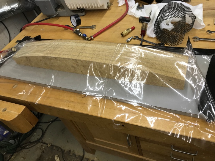
The remainder of the plastic vacuum ‘bag’ is taped down. You want the plastic to be as loose as possible so there is no bridging of gaps.. every little corner wants to be sucked in as best as you can get it..
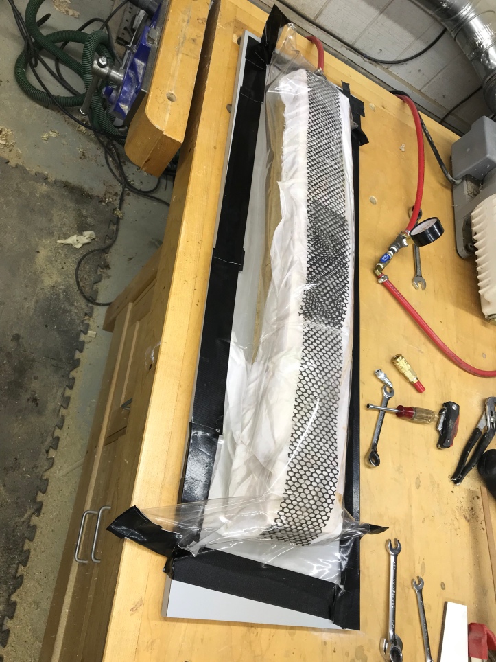
Here is the curved front piece being clamped onto the form with vacuum. Why do it this way? The gauge shows 25hg, which is approx 12 psi. These planks are 5″x32″ (or 160 sq inches).. 12 psi x 160 = 1,920 pounds of total clamping pressure in the exact shape of my curved control panel front. Can this be done with regular clamps? Absolutely.. Vacuum just does a much better job. Plus – I had all of the equipment from other projects.
A quick video showing the pump getting turned on:
Control Panel vacuum clamping video
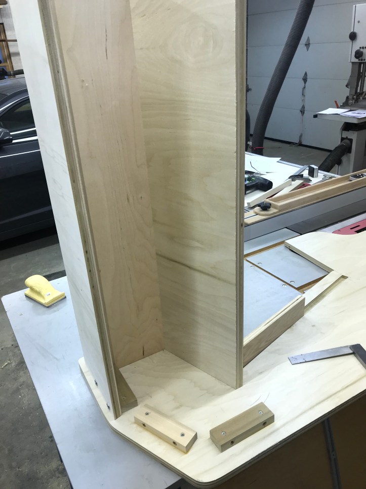
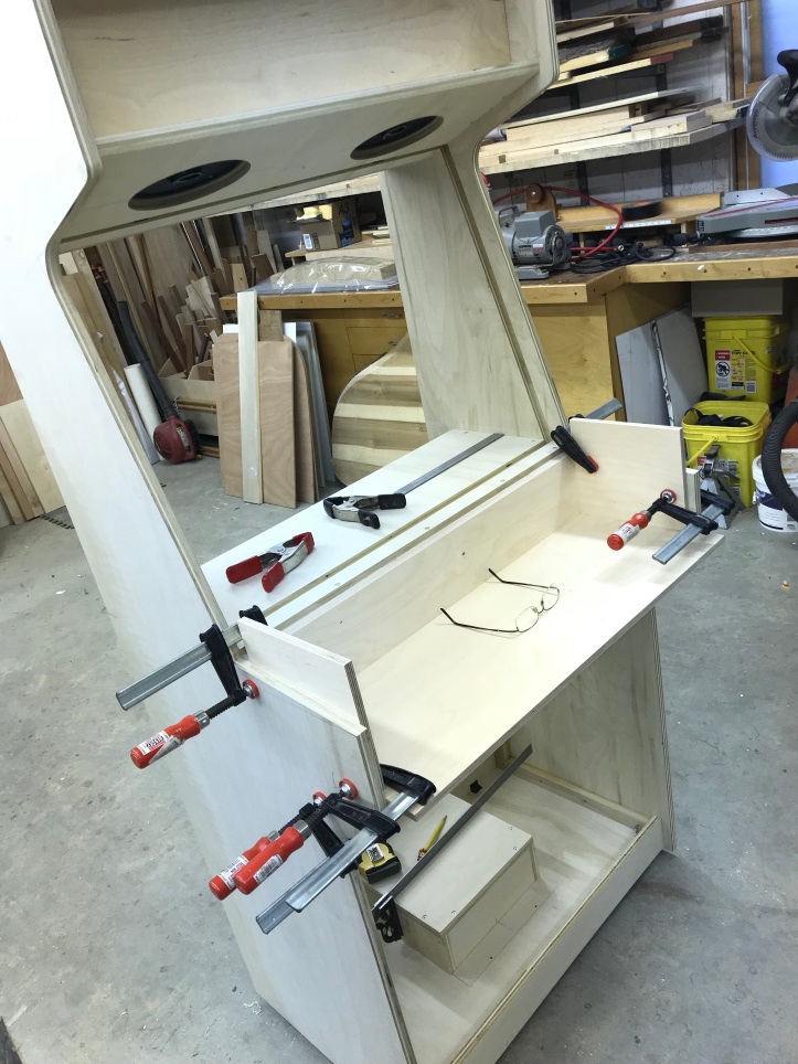
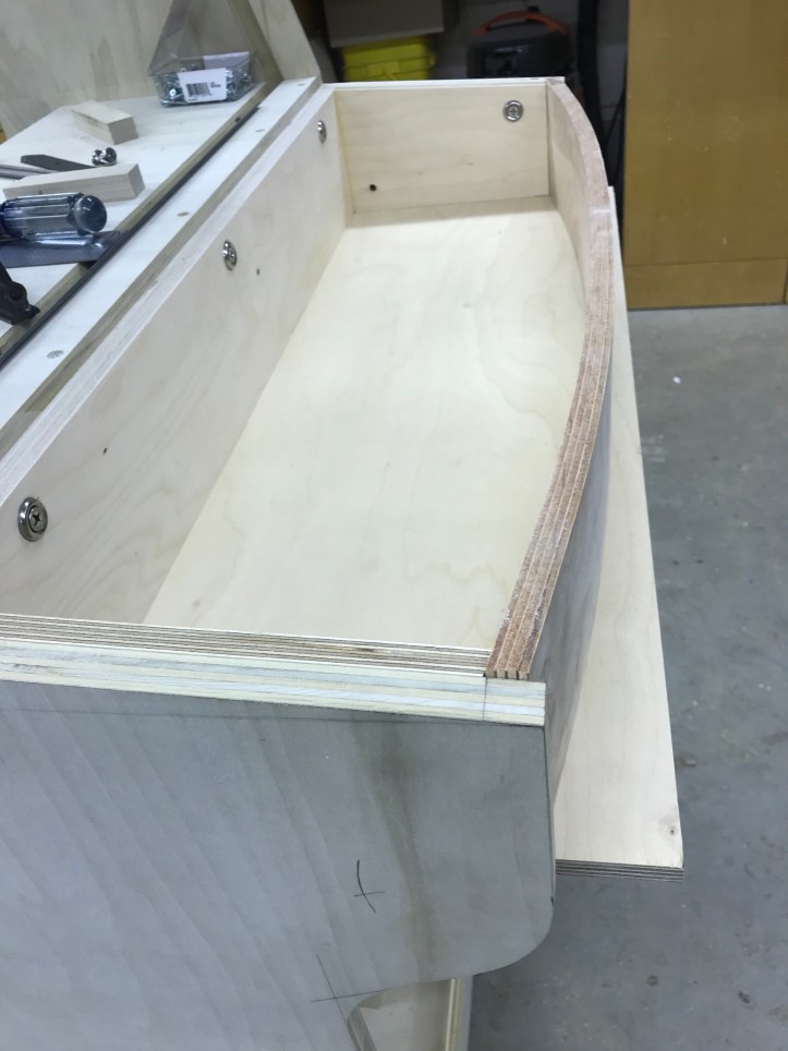
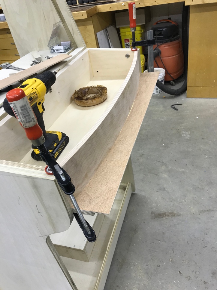
I started the CP box which will be removable (as most are). Here is the back, bottom and sides in place. I can add the mounting screws and threaded inserts easily now where I know its positioned correctly. Plus all of the measurements off the plan worked!
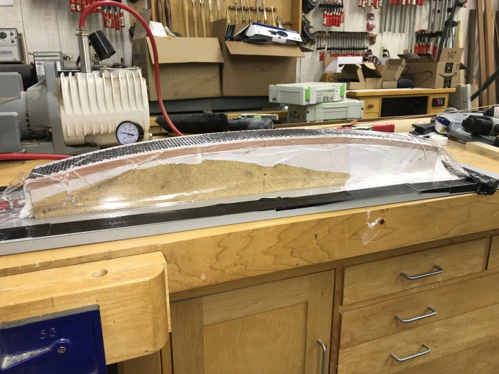
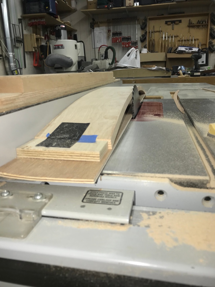
The curved front came out pretty nice. I ran the bottom edge across the jointer to clean it up and trimmed the ends to fit inside the CP box. Using the form I vacuumed it on to cut the ends made it real simple. I used the table saw miter gauge and trimmed each end so that it fit tight on the ends. Here it is a still tall.. cutting it so the control panel will lay flat along the entire curved face is tricky.
Here is how I did it.. I screwed a couple of stop blocks to the exact width of the CP box (31″ in my case) onto a piece of scrap plywood. The idea is to keep the curved piece from flattening out and changing the cut..
This shot is after the cut, the blade tilted and the flat side up against the fence..
One (what turned out to be) a small screwup here.. I had the blade tiled to 12 degrees which is the angle the box sides meet the back face of the curved part.. It SHOULD have been tilted to 5 degrees, the angle of the down slope of the control panel…
The outcome was that the curved panel met the underside of the control panel tight at the ends and had a 1/8″ gap in the center – NOT what I wanted! After being a bit angry at myself for the mistake – the solution turned out to be quite simple. I re-adjusted the blade to the 5 degree angle and bumped the fence in 1/4″ and re-cut the panel.
The result is a nice tight fit where the CP meets the curved face. Phew..
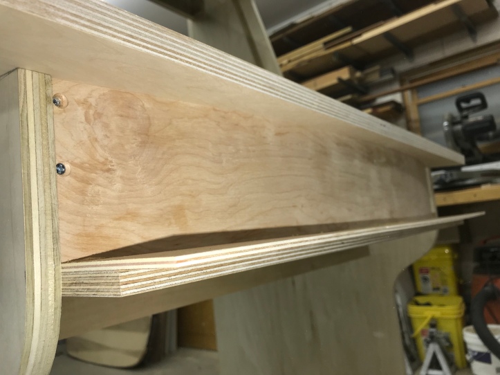
Here I’m gluing/clamping on a 1/4″ plywood spacer to the bottom of the curved piece. The upside of my mistake is that I could have messed this up more than once, re-cut the curve and added more to the bottom. So in the end, not a big deal.
Next, trim off the excess on the front with the bandsaw – get it close w/o touching.. Also notice the tight lamination of the 4 x 1/8″ plywood.. Vacuum clamping at it’s best!
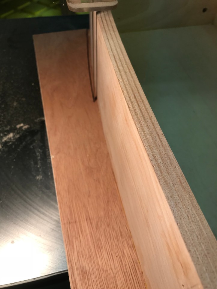
Back to the pattern bit at the router table and trim the face of the CP box flush.
Curved part completed. It will end up laminated and not all that visible.. But it takes a little bit of the boxy cabinet look away..
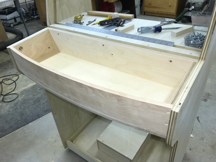
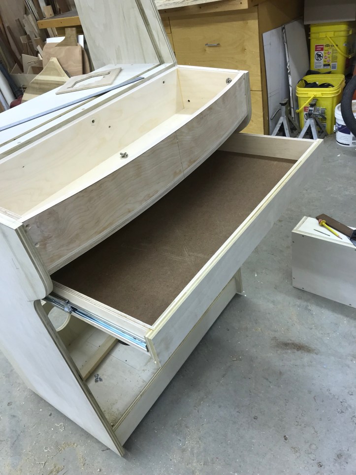
I wanted a drawer for the mouse and keyboard. Not sure if it will even get a handle – its really just storage for that and maybe some papers/diagrams I may need down the line.
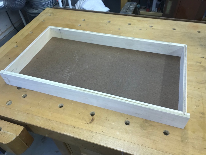
Nothing complicated about it.. Drawer box and bottom.
Using scrap as guides helps with alignment of the drawer slides. Use the guide to draw the center line on both sides of the cabinet w/o trying to measure and get the lines squared up.
Hides underneath the CP nicely.
Next up the coin door – I have two European hinges on it and plan to add a center one because the door/coin door are a bit on the heavy side. These hinges are very adjustable to control the gap around the perimeter. Great to work with this style hinges.
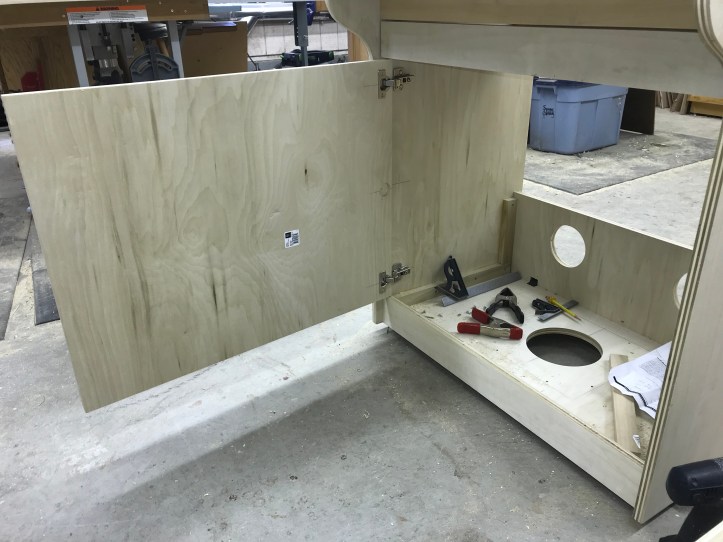
While the door was mounted – I made a scrap template that matches the size of the opening needed for the coin door. My design called for the coin door to be ~2 1/2″ from the top of the door – using the template – I taped it to the door and found it looked a little nicer at 3 1/2″ from the top edge.. So I went with that.
I cut the hole using a jig saw and dropped the coin door in place.. It uses 10-24 carriage bolts. It would be best if I could use the drill press to get a nice perpendicular hole.. But the door is to big – a block pre-drilled at the press is a nice guide to make sure the hole does not get off course.. Slightly crooked carriage bolt heads are a small detail – but annoying to look at!
Mounted in place..
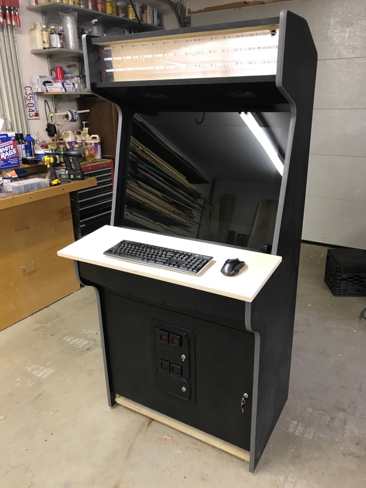
Here’s where I’m at now..
I’ll paint the carriage bolts black for final assembly..
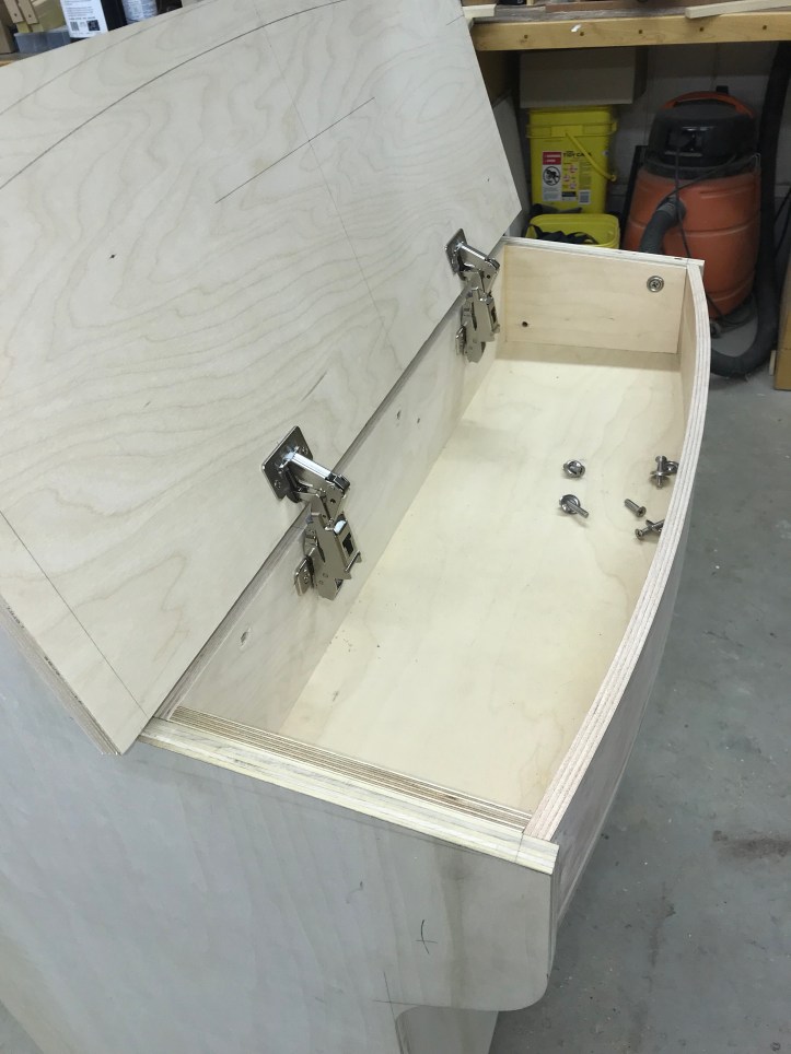
Another good use for the European hinges: Everyone is going to want to see inside the control panel and I’m certain I will have it off and on dozens of times during construction & wiring. It happened to work out that they close at greater than 90 deg of a traditional door and swing an extra 5 deg. They are quick release so they click apart/together easily.
Waiting on artwork before final cutting and drilling the panel.
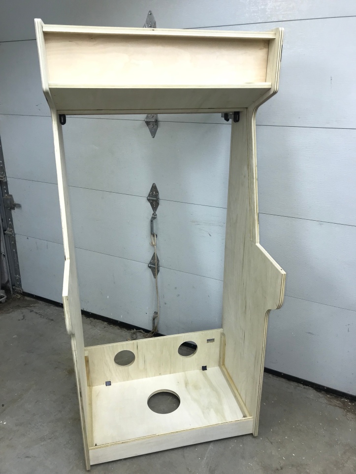
My original design was to have a full length door to access the rear. But once it was all together I realized a couple things. First – I have considerable access through the front with the coin door, drawer and control box being removable. Second, the cabinet seemed a bit wobbly and a fixed panel in the back would add rigidity. Second – I would have had to purchase another sheet of plywood for a full panel. But I did have scrap to create a fixed lower panel and a door for behind the monitor.
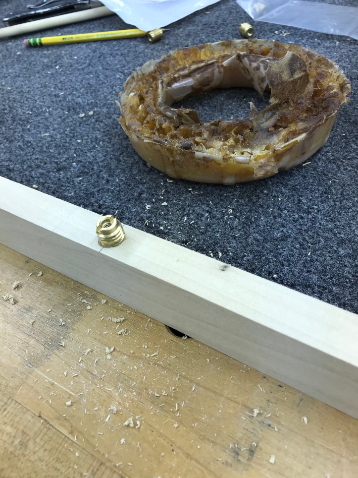
Trick for any screws – lubricate them with a toilet bowl wax ring. These threaded inserts were going into the stop blocks real hard.. Add wax and they spin in nice and easy. This ring is probably near 20 years old. For $3 – its worth having one around.
Door and fixed panel. I’ll go back and modify the plans to match.

95% of the woodworking is complete now. I have a few adjustments to make here and there. The plan is to disassemble, paint some areas and laminate the sides and front facing parts.
I’ve taken the cabinet apart to work on painting and laminating the parts. The interior will remain bare wood. There are many edges where painting them flat black has the potential to cover up any mistakes. I’m going to laminate the back panels, but there really is no need to do edge banding on them.. Those edges get paint. I’m painting the side panel edges black so that if the T-Track has any small gaps, they will be black like the side panels. I also painted the inside of the speaker and fan openings. The bottom of the control panel box got black paint.
The drawer and coin door get edge banding – since they are most likely to be seen opened. I started with the panel sides and will do the top and bottom once the sides are trimmed. A trim router is a necessity for this type of work.
My side panels can be fit together to conserve materials. Use a 1″ (or so) block and trace around the panels on the back of the laminate.

Now the tough part – I tried cutting the material using a jig saw using the gap between the benches. One side fell, tore and that was that. I tried to cut the other side and had another sawing mistake and essentially ruined the entire sheet of laminate. So much for conserving material. There is enough left that I can use it for one of the large panels, etc.. But I will come up with a better way to do this without destroying the next sheet..
Bare wood is best with 2 coats of contact cement due to absorption. I put one on, let it dry 30 minutes, then add a second coat to the wood and a single coat on the laminate pieces and allow it to dry 30 minutes. Contact cement should be slightly tacky to the touch, like a PostIT note, not wet like glue. Its amazingly strong when lined up to stick to itself this way.
Once dry – you get one shot at attaching the laminate. Best to line up larger sheets on long sticks/dowels – then pull them out one at a time and stick the sheet in place. Use a J-roller to apply pressure to finish laminating the panel.
Here is part of the trimming process. Router table and flush trim bit to clean up all of the overhang and openings. It makes quite the mess. The contact cement gums up the bearing on the router bit and clumps end up on the edge you are trying to cut. You end up making a rough first pass – cleaning everything away – cleaning the edge and bit with acetone and then making a finish pass.
Inside the speaker opening, inside edge painted black.
Speaker panel all trimmed and cleaned up. My build has lots of panels and edges.
Here most of the work is done. I have to do the sides and one more back panel. Then the cabinet can go back together.
Laminating all of these parts isn’t particularly difficult – it is time consuming.. I have 10-15 hours into it with more to go. Probably still a better look than just paint.
One of he last of the lamination steps – covering the inside edges of the sides. Glue, stick, trim with a patter bit on the router table.
It worked out that the only place there will be seams is this little 4″ section on the top/ back of the cab.. I can live with that.
Back to cutting the laminate – layout done..
Cutting with shears – done. No problem this time. In the end – I’m pretty sure I would have needed 3 sheets to do what I wanted to do anyway. I just had a little more waste than expected.
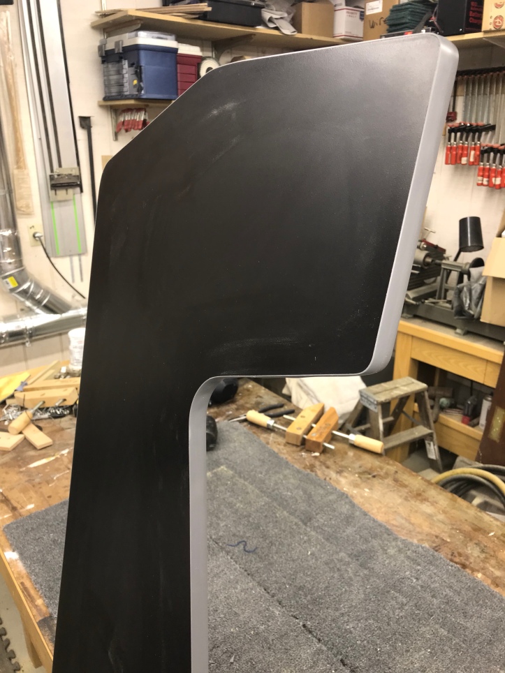
Inside and outside lamination complete – along with about an hour of shop cleanup. I had thought I’d decided on a T-molding color, then looked one last time and have 2 more samples coming. I’ll install them before setting up the cabinet.
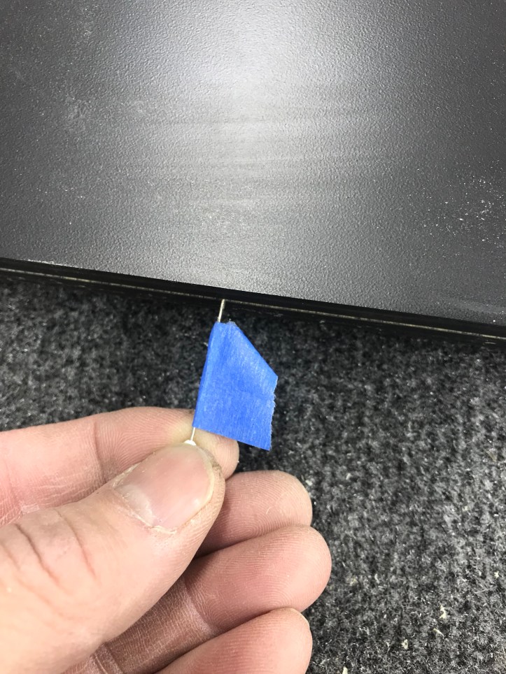
So I decided on grey T-Molding. (Boring?) I cut the 1/16″ slot with the standard slot cutter and a router. Before I installed the molding, I used a long pin with a piece of tape as depth gauge and followed the slot all the way around to make sure the router didn’t wander. The cut was so smooth it was hard to tell if the bearing was actually touching at all times. Pulling off the molding to recut the slot is what I wanted to avoid. Good news – I cut it right the first time.
I used a carving mallet to tap the T-Molding in. Here are the snips needed to get around the inside and outside corners so the stuff doesn’t buckle
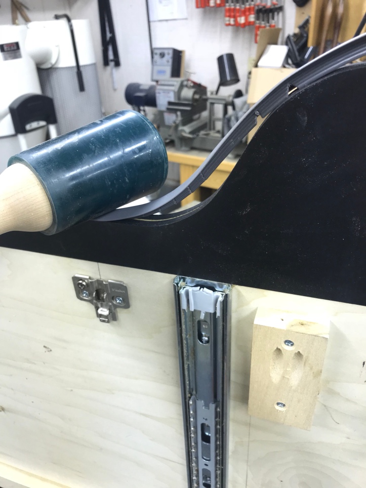
I found even the mallet seemed to be marking the plastic a bit – old sock here to help soften the blow.
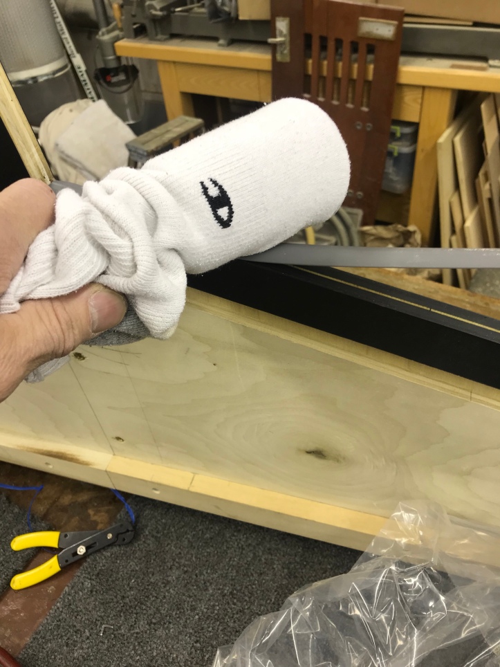
Completed installation.
Cabinet assembly is up next.
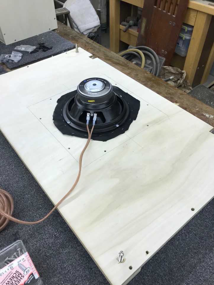
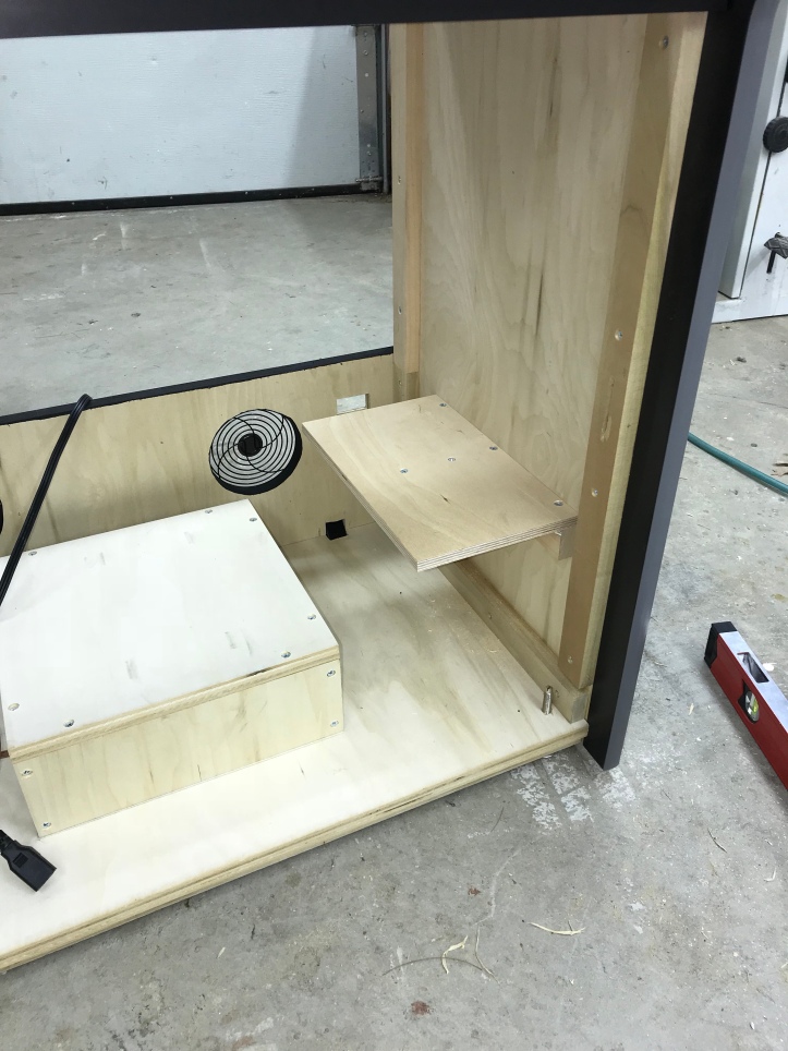
I got started on the bottom panel first.. My cabinet will be for Mame games (maybe others?) but it also has the potential to be a jukebox too.. So I put in an inexpensive subwoofer just in case something in the future can take advantage of it – speaker fabric, faced downward, insulation and will be enclosed.
Black screws are hard to find, but simple to make. Just a detail.. These are for the wheels for when I tilt/roll the cabinet.
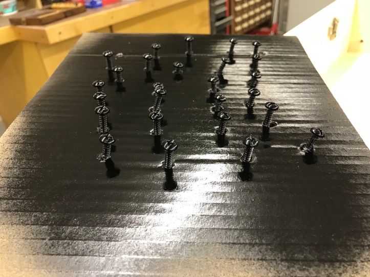
Shiny black screws that no one will ever see – much nicer than silver colored screws that no one will ever see.
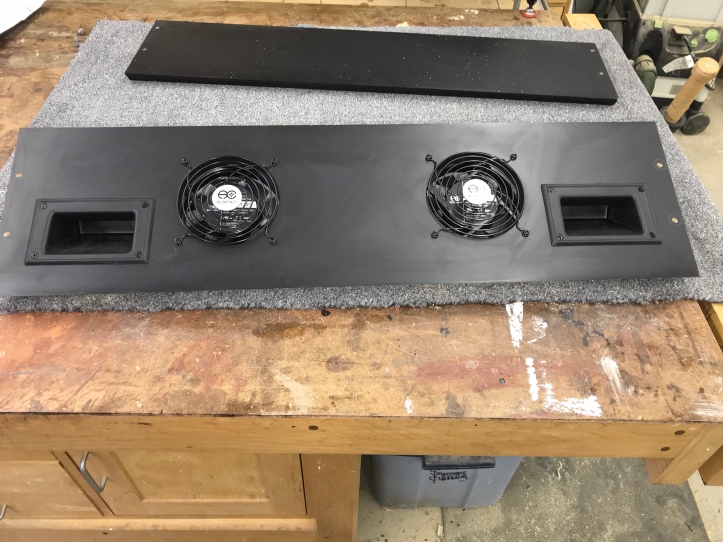
My top panel has cooling fans and hand holds. Not sure the fans will even be necessary or if it will get hot inside the cabinet.. They are very quiet so it certainly can’t hurt.
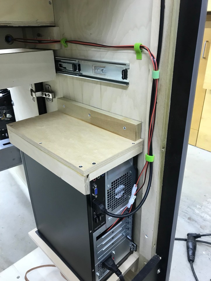
I didn’t take pics of the cabinet going back together – all of the parts were fit prior to adding the laminate. Here is a small shelf to mount the PC.. Haven’t quite decided if I’m going to drill holes and screw the PC on .. or just make straps.
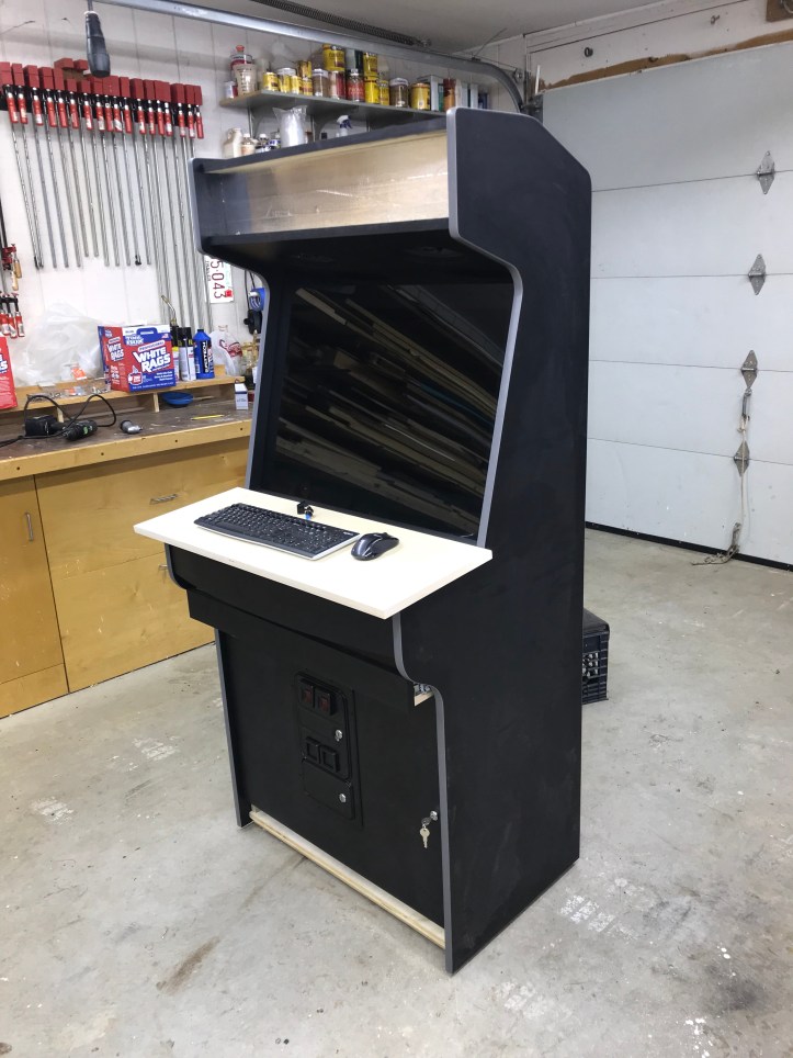
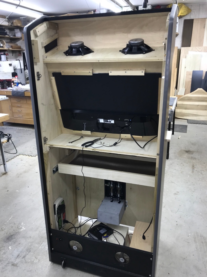
Here is is set up – I went with 1/4″ grey tempered glass. Not CHEAP! But it really looks nice.. The control panel blank just clicks in place with the European hinges.
The top speakers will also be insulated and in a box. My monitor mount is quite simple – wood clamps to hold it in place. Here I have the power sensing strip in place and the rear power connector set up.
On the lower blocks on the mount – I tapped in a couple of bolts as adjusters to level the monitor in the bezel. Left and right adjustment is a matter of just moving it left and right. Then I just tighten all of the mounts to lock it in..
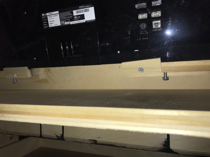
Here is the monitor with the bezel removed and the LCD flipped over off of the backer panel. The LCD was not sitting flush against my bezel and I needed to add a backer to the existing frame to move it out a bit.
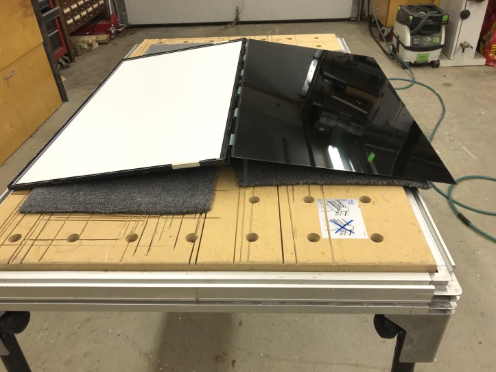
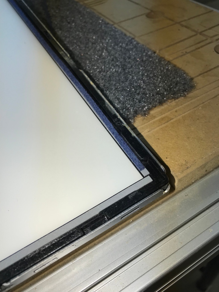
Here is a thin 1/8″ strip of adhesive backed felt (blue) that I added to the existing edge gasket. I used compressed air to get every spec of dust out of the monitor, then cleaned the LCD and the tempered glass and quickly got it all together in the cabinet so that there would not be any trapped dust.
Note: The first time around I just mounted the monitor to the bezel. Unfortunately the LCD slides all over the place. So I had to take the monitor back off and tape the edge of the LCD in place so that it could not move.. For this type of monitor and mounting method – its a must. I happened to have foil tape (used for duct work – but not Duck tape). The foil tape is perfect for this..
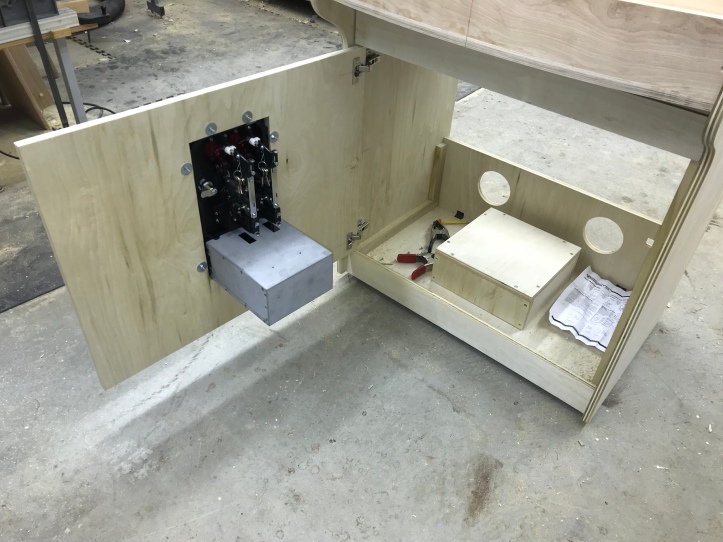
I went with a smart strip and the panel mount switch. Connectors, heat shrink insulation. I rather like this part of the process – getting all of the wiring in place.

This next part I will go into a lot of detail – not necessarily because it is particularly complicated – but because I could not find this information anywhere – I scoured the internet and found nothing on this specific type of power switch.. So Google, Bing and any other search engines – find this so it can help some others out!
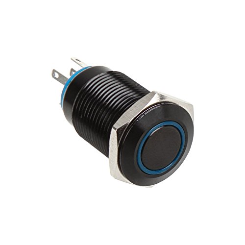
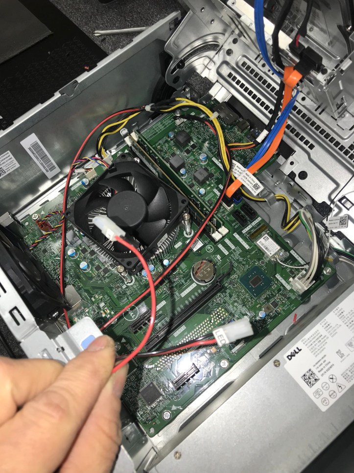
The PC I got is a Dell Inspiron 3668. My plan is to put a lighted LCD switch below the CP. One switch powers on the PC – the power strip senses the power coming on and turns on everything else in the cabinet.
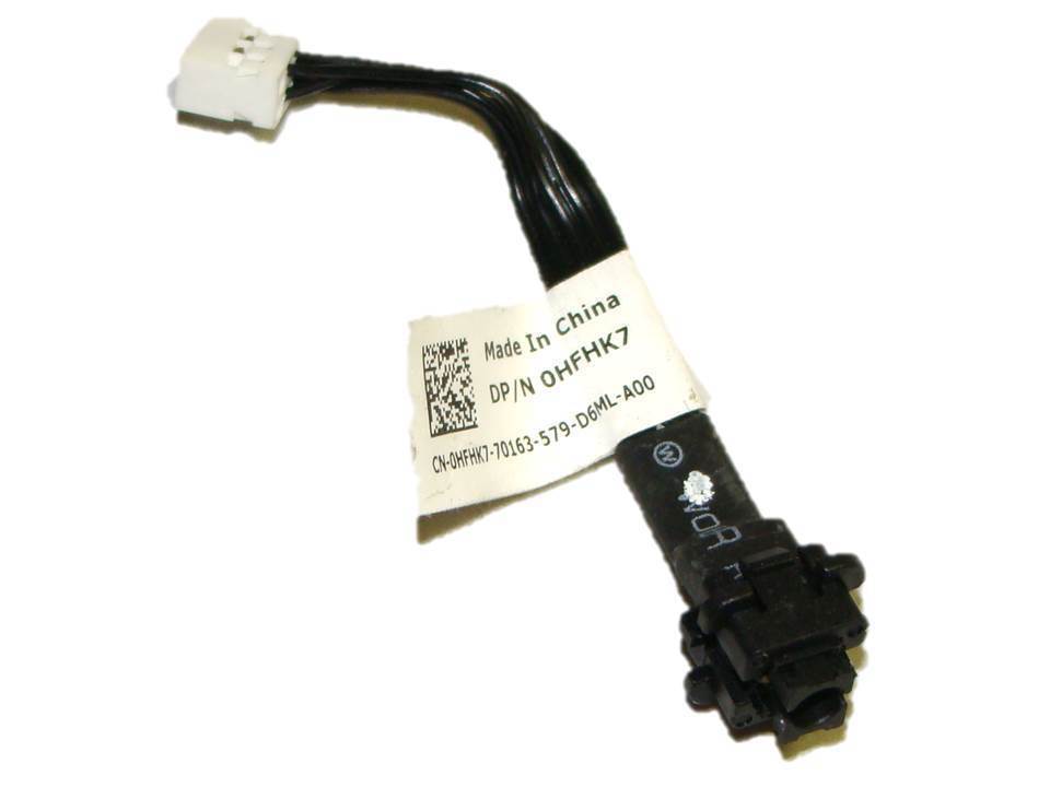
The internal switch on the PC is an 0HKFHK7 (Above). All of the Dell power switch connectors I found documentation on were 10 pins. This is an 8 pin power switch connector.
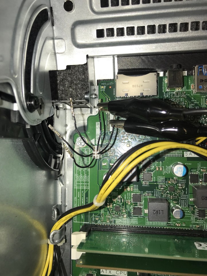
Below is the connector on the PC for the power switch that I could not find the pinouts for. But… I was able to figure out what the pins do to set up my remote switch.
1 – LED negative
2 – LED 5V+
3 – Momentary switch
4/5 – Unused
6/7 – Momentary Switch (must be tied together or the BIOS will report defective switch hardware)

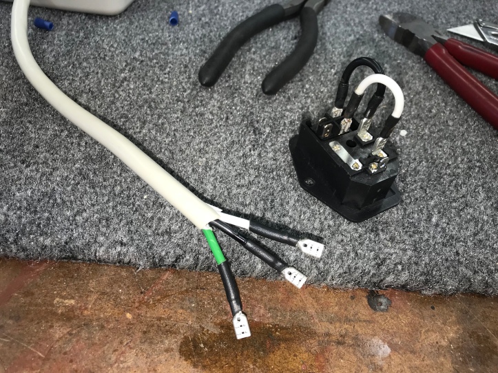
I cut the original switch off, saved the connector and added dupont pins. Cutting open the switch and a little testing got this part figured out.
I’ll add proper connectors, mount the PC and get the remote switch set up next.
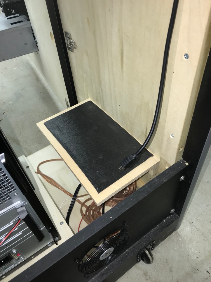
I got the connectors all set up after some fiddling around. The remote power switch (also called a vandal switch it seems) has an LED ring that can run 5v or 12v. The 12v is a little brighter of course. I wanted it set up to be lit all the time, however the PC switch LED was only lit when the PC was on..
That said – PC’s have standby power when the machine is off so that the power switch can trigger the rest of the machine to turn in.. Standby power is normally 5v. I got a little lucky in that my power supply has 12v standby power.. So I tapped into that for the LED ring.. I also crimped on a couple of connectors so I can get everything apart easily.
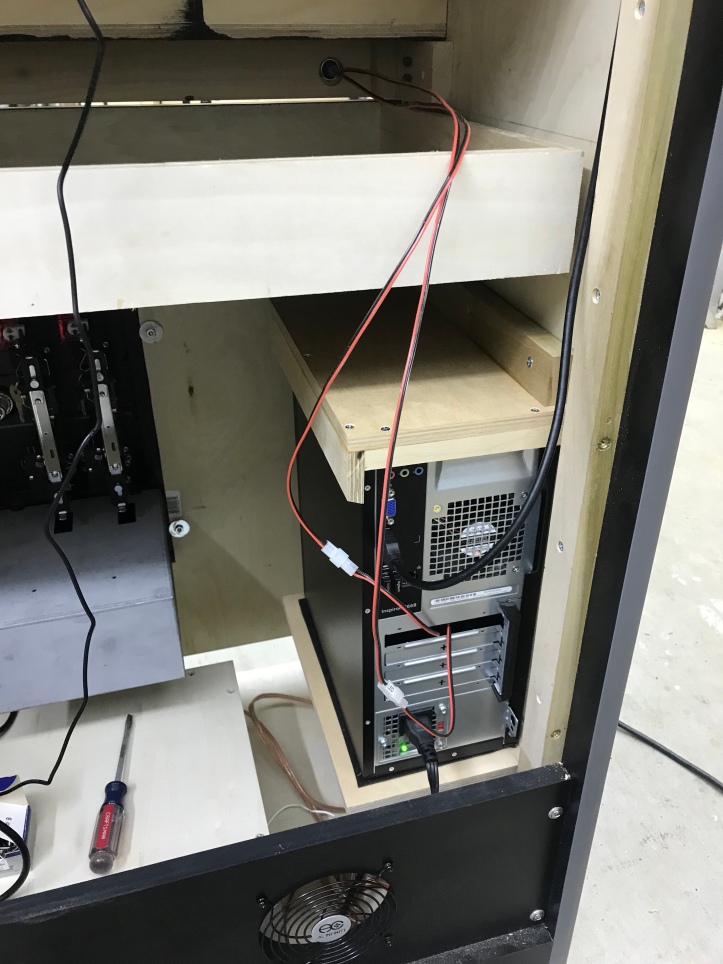
I had some cheap harbor Freight tool box liner which is a thin foam material. The PC shelf, side and top got it to insulate any vibrations so the cabinet didn’t develop a hum over time..
To secure the PC – I ended up making a cap out of scrap wood that snugly holds it in place. The strips go around the side and front and the cap has some of that foam in it. I put some on the blocking that attaches the cap to the side as a gasket.. just in case some PC vibrations decided to use the side panel as a giant sounding board.
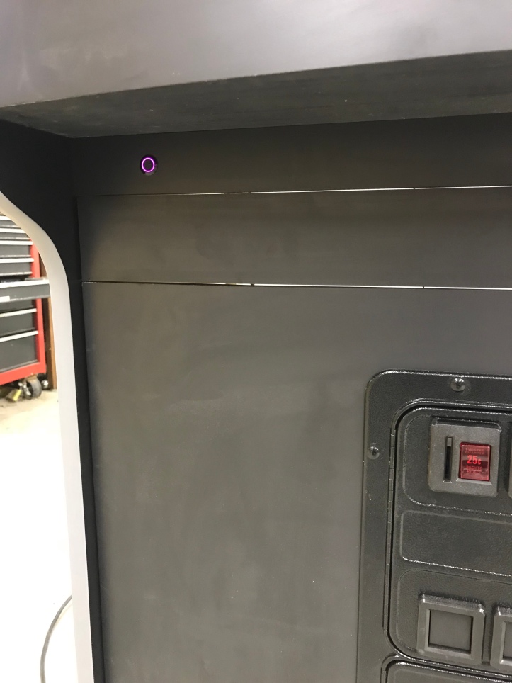
All that for a little LED ring..
I’m planning on getting the speakers and marquee LEDs in place this weekend..
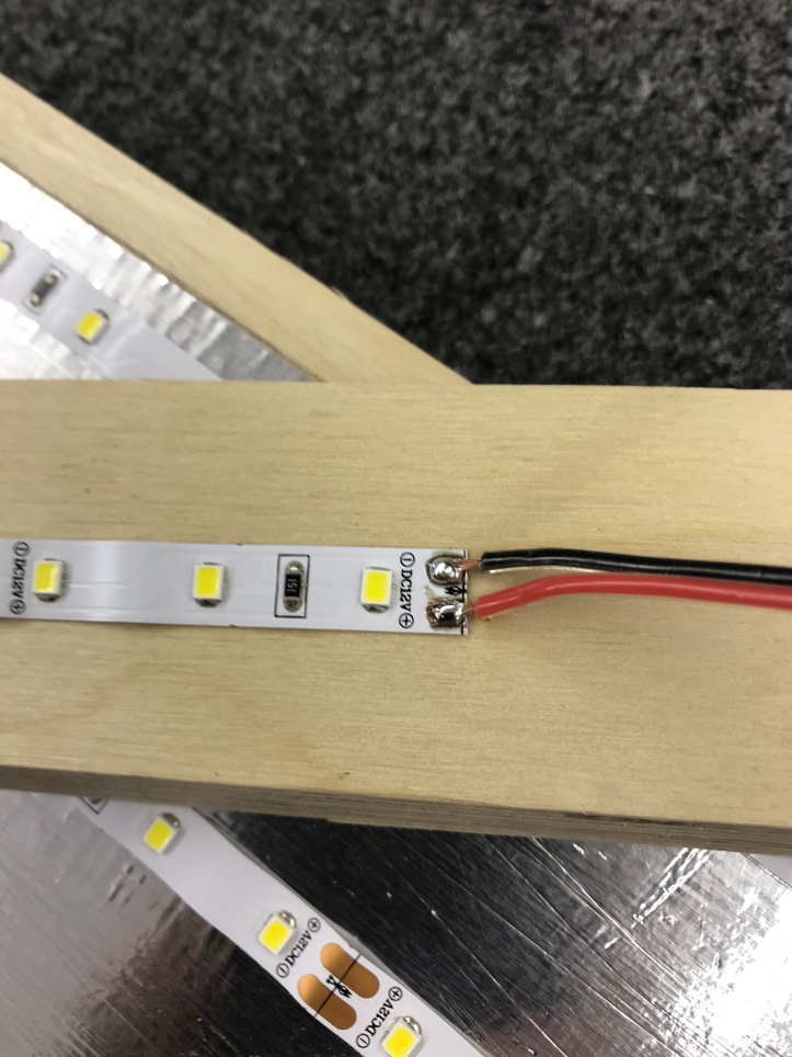
Great day of wiring and getting things in place. I started with the marquee LED strips. These turned out to be pretty simple – I had never worked them before and it looked like they could be a pain to solder.
I cut off a the smallest section of the strip, put a little solder ball on each pad a then soldered a lead wire into it. It was as easy as the YouTube video made it look.
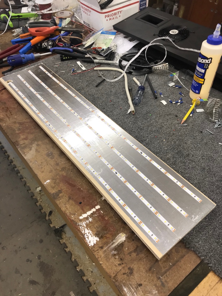
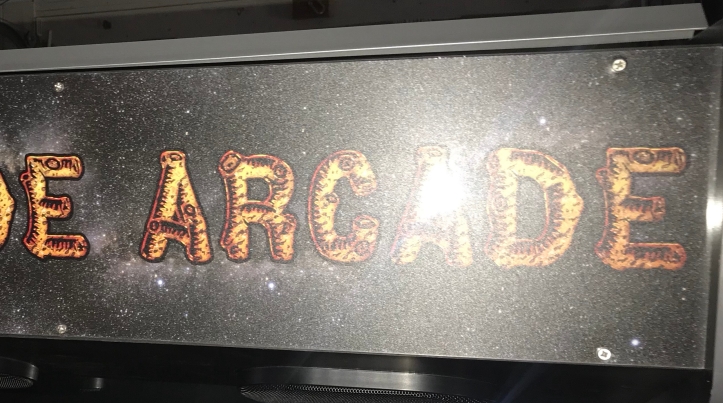
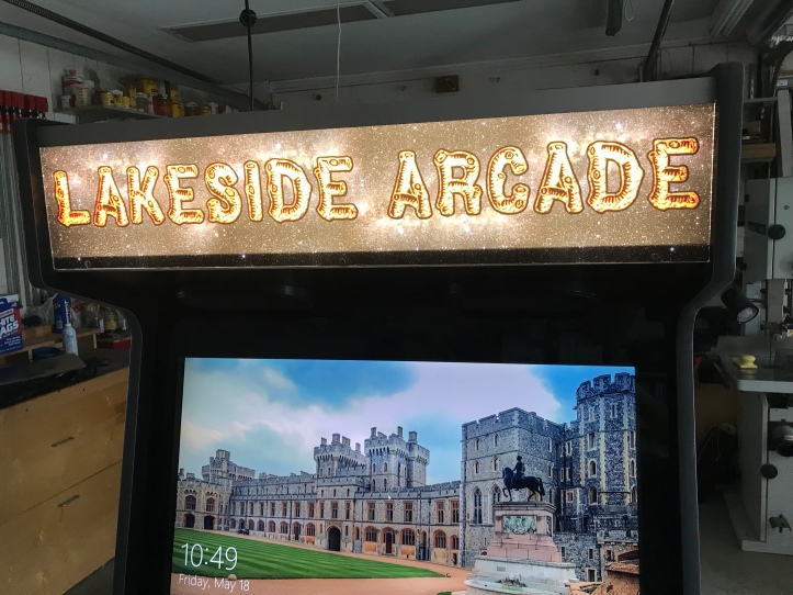
My marquee with strips in place ready for connecting wires.
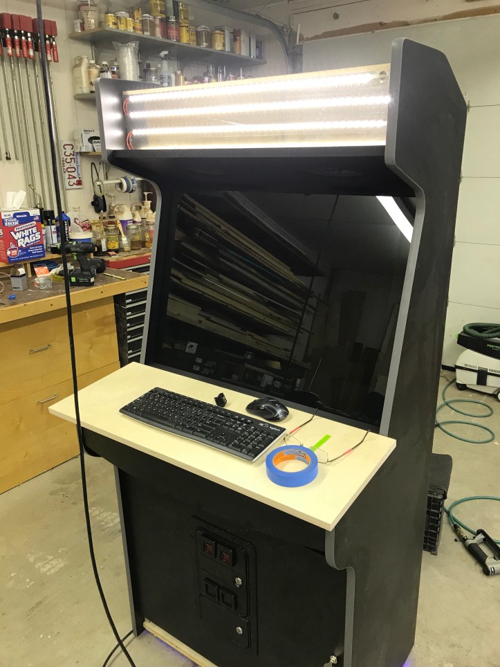
All lit up and ready to go. I may need some diffuser material to flatten out the pattern depending on how it looks behind the marquee.
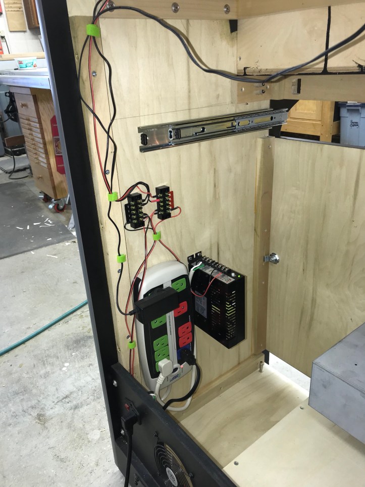
Here is how I decided to power the cabinet – there are a few 12V items (LED strips, AMP, reject button bulbs) – much simpler to connect them to terminal blocks. The arcade power supply mounted next to the strip kept everything pretty compact.
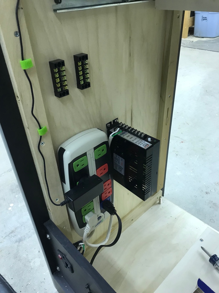
I borrowed this Velcro strip idea from someone in the forum (Flynn’s Arcade maybe?) its a great way to manage wires and create pathways. I ran out of it.. Need to get more to finish cleaning up the cabinet.
A few more wires getting into position on the 12v terminal blocks.
Upper speakers in place – I filled the compartment with insulation and closed it up. The small amplifier works quite well. The best place to put it was right behind the monitor and above the PC.
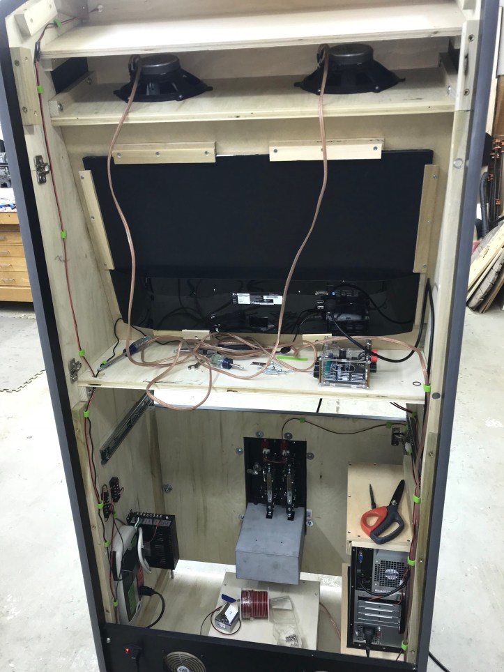
The top parts in place for the last time (hopefully). Cooling fans are under these grates, but they are a little louder than I expected. So they will stay unplugged until I determine if they are actually needed – or maybe I can find a temperature sensing controller that can spin them up at a variable speed as the cabinet heats up.. The hand holds are working out really nice.. Glad I saw these on someones page.
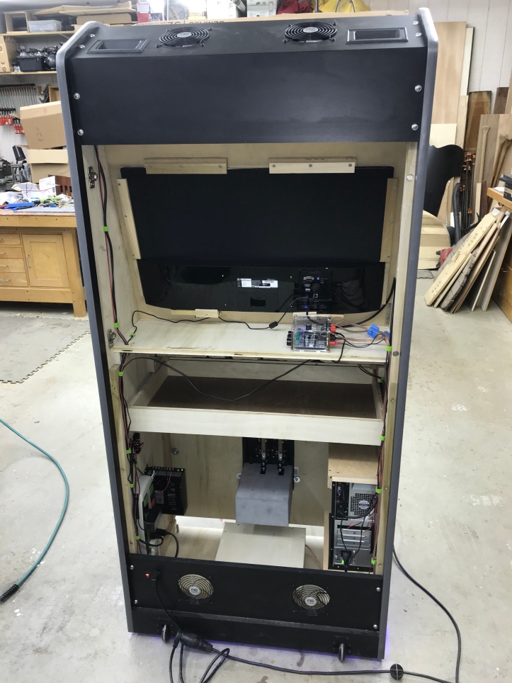
Here is where I am at the moment – Still need to attach the toe kick and clean up a few items. I’ll be in a bit of a holding pattern for a while until all of the artwork is finalized and gets printed up.
As for the sound – I connected the amp directly to my iPhone and ran some songs off my playlist to get the levels balanced out etc.. For an arcade cabinet – this box sounds really good. People said that the subwoofer would need a port so that it didn’t sound muted.. I put my hand over the hole where the speaker wire came out and there was a steady breeze – pretty cool. I did cut a hole in the front to let it breath just a bit more and the bass is reasonable. I’ll mess with it more once the whole thing is enclosed. Audio off of the iPhone is way better than expected.
Audio from the PC is not not right yet. There is background hiss and other noise that makes no sense.. Its certainly coming from the PC since everything is identical except the source.
While I wait on the control panel artwork – I’ll start getting the software set up to auto boot, remote access, etc.. clean the shop – what a mess once you get wiring..
Artwork completed and printed. I had Game On Grafix print the marquee and the CP overlay. Their Ultimate package prints directly onto plexiglass with a white diffusion layer. I recommend getting the extra layer of plexi to go over the marquee. It is printed on top of the glass – not behind it.. So you still need a sandwich of plexi to get it all right.
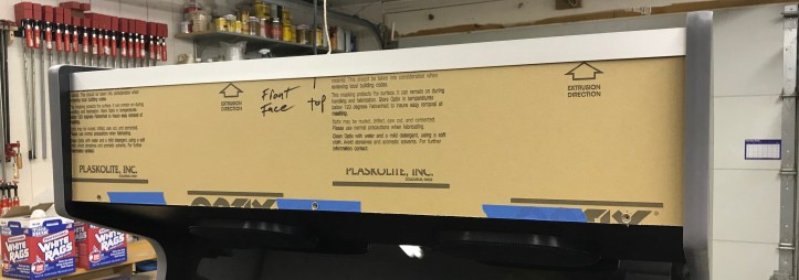
Leave the paper on until you have everything fit or course. I’m mounting my marquee a bit non-traditionally. The speaker panel is at an angle and there wasn’t a good way to get a retainer bent and all of the plastic variants of retainers were too short. My solution is 1″ x 1/16″ aluminium angle stock that I picked up at the hardware store. Top piece is simple since it was at 90 deg. If you look close – I’m screwing the marquee directly to the cabinet using #6 sheet metal screws.
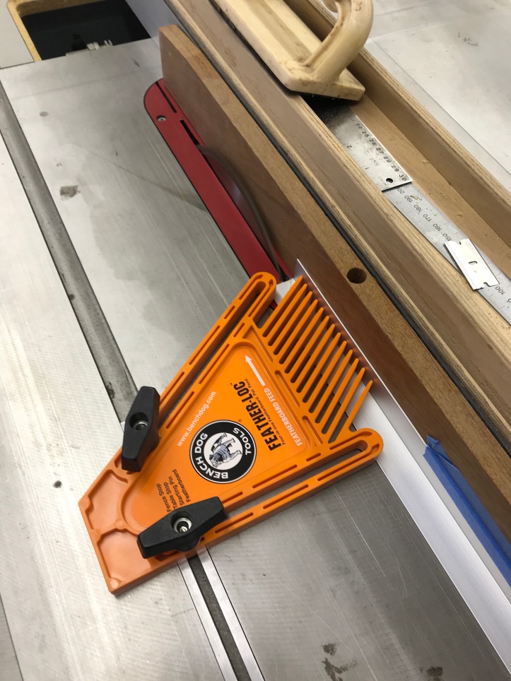
Here is the clever part.. For the lower retainer – I cut one side to 1/8″ to match the thickness of the plexi layers. Tape the aluminum to a guide so you can slide the whole thing through slowly and let the blade do all the work. The feather board will keep everything in place so that there are no mishaps with saw blades and metal!
Here is the lower retainer: The thin edge covers the marquee, fits flush against the speaker panel and covers the screws. The bottom retainer will be double stick taped in place. The upper retainer gets a couple screws on the top of the cabinet.
Someone mentioned that I had WAY too much backlighting and my marquee would be washed out.. That’s 100% correct. I’ll be reducing the LEDs down to 2 strands and toning this down a lot!
Problem solved for $5.85

Dimmer works perfect. If you are in the process of a build and are using LED strips for backlighting, I’d just get one and make it part of the design.
Super simple and you will spend much less time trying to mask LEDs or having to guess how many strings of lights you should use.
Now to get the control panel made..
Lakeside Arcade: Making the Control Panel

I challenge you to Space Invaders!
Now I know where my paper plates are disappearing to. 😉
[…] Cabinet Construction Begins: Lakeside Arcade […]
This is an amazing project! Found a picture of your cabinet at Pinterest and followed that to Arcadecontroll and here to your wordpress site! I am in the planning of building something simular and find you cabinet design beatifull and inspiring. Is there any possibility that you could share your sketchup files as a starting point for me? I would be most gratefull. Greatings from Norway!
Hi Jens, thank you 🙂 I’m happy to share my plans with you. I need to make a couple of small changes to the sketchup drawings to match some changes that I made.
It will take me a couple of days.
Do you want the actual sketchup drawings? or just a PDF set of plans?
Thank you! I would like the sketchup files if possible.
https://bperkins.wordpress.com/downloads/
Here is a link to the sketchup file. Let me know if it works out.
Fantastic, works great! Thanks a lot!
[…] I spent about 6 months designing a cabinet in Sketchup, acquiring components and perusing the Arcade Controls Forum formulating and overall design. In December of 2017 I started the actual cabinet construction. […]
This is awesome! Do you have the pdf of your build? Do you have a photoshop or adobe file for side art and or at least control panel design?
Do you have have PDF of the build?! and or photoshop file or template to create side art or control panel art?! I’m getting ready to try and pull this off!
I fall in love with this Angel Bob. Great work, it is exactly my dream cab. It is so beautiful. Beyond every design of cabins in the world. It is simple and perfect. Bob, I try to make this beauty with MDF. You think is it done with MDF? And is there an option to get your plans within PDF. By the way we use cm instead of inch but This situation cant stop me 🙂 I am ready for everything for this gorgeous Angel.
Hi – thank you – their is a link to PDF plans here.. MDF should not be an issue. Good luck!
https://bperkins.wordpress.com/downloads/
[…] on the BYOAC Forum that you could end up with more than one machine.. My Mame cabinet – Lakeside Arcade – was fun to build and gets considerable use. But its at a summer home and isn’t all […]
Hi Bob. It’s been almost nine tough months. It’s all start with your plans. Finally I made my arcade and share photos on my instagram account. I want you to take a look pls. A big thank you my friend. A dream come true thanks to you. Take care…
WOW! That is fantastic! I’m very flattered and glad it worked out for you! If its OK – I’d like to repost some of the pictures. Really nice work!
I am so glad you like it. Of course you can share all photos of my arcade. Even I can send new photos to you. Pls add my instagram account, so I can easily send new ones.
how much do you charge for a plan cabinet build for a 32-inch monitor with 2 players 8 button cutouts and cutouts for 6×9 and 8-inch sub?
Hi Bob, like one of your other posters, I found this through the arcade controls site, and it was by far the best example and help for building my own. My son’s “birthday present” that has been 9 months in the making and getting close to finished (different design, but many “cool” features and decisions).
Anyhow, I had a couple electrical questions:
– I’ve come to find out that there are “smart” power strips that allow one plugged-in device who powers on, to engage the other outlets. However, “smart” now seems to refer to WIFI controlled strips. Do you have any links to recommended or known strips that do how you set yours up (so that the PC coming on, would start the rest)?
Also, did you use a standalone power supply for your powered devices that required 12v and that type of terminations (led strips, fans, etc), and was the use of terminal blocks because you didn’t have enough connections on the power supply?
Finally, you said about using “one” led light – are you recommending a single bulb led instead of strip lights? Do you have an example?
Thanks again
Hi Max – Glad I could help.
I used this as the power for the Ultimate I/O and 12v.
I used terminal blocks because connecting everything to just 2 screws is difficult and looks horrible. The strips are easier in the long run.
I used this smart strip: https://www.amazon.com/gp/product/B0006PUDQK/ref=ppx_yo_dt_b_search_asin_title?ie=UTF8&psc=1
They make a smaller one – I ended up having more outlets than I needed. But it’s worked great from day 1.
Not sure what you are talking about on the ‘one’ LED light….
Happy to help
Thanks so much Bob.
I assume when you say having to connect everything to 2 screws would be difficult – is because there are only two terminals on the power supply for the 12v connections?
In regards to my last question, quoting your last comments:
” If you are in the process of a build and are using LED strips for backlighting, I’d just get one and make it part of the design.
Super simple and you will spend much less time trying to mask LEDs or having to guess how many strings of lights you should use.”
I didn’t know if you meant “just get one” as in one led strip, or one LED light?
Hi Bob,
I have a problem, you might have some insight.
I got both the same Blee BL-9916 power supply and the same Smart Strip you do. I have actually reviewed your wiring in your pictures and verified that I have the smart strip connected to the power supply the same as you do. Finally, I have verified through a couple of sources that my on/off male power socket mounted to the cabinet is wired properly.
Using my digital multimeter, I have verified that the +5v and -5v connectors are registering properly. However, the +12v is registering -3v. The adjustment knob only adjusts minimally.
I have heard that this could be that neutral/power wires are reversed, but I don’t see that (and would the other +-5v not be off as well)?
Any thoughts why?
This is the male socket that I am using (https://www.amazon.com/gp/product/B06XNMT3WL/ref=ppx_yo_dt_b_search_asin_title?ie=UTF8&psc=1)
Hi – Hard to tell without pics of your actual wiring job. You may want to plug the power cord directly into a wall outlet and make sure the power supply is good. (i.e. Don’t use the smart strip or rear outlet for now).. Line, neutral, ground.. and set the power supply up first.. In case you don’t know – the small blade on the power cord is line (hot – normally black)) and the larger blade is neutral (normally white) Green=ground..
That said – I’ve never heard of your issue.. make sure it is set to 110 and not 220 (little hidden switch on the bottom)
Correct – there are only 2 screws on the power supply for things and I needed more. The terminal strip made is easier.
I had backlight LEDs, ground effect LED’s and some other stuff.
For the marquee – the LED strips I had were super bright. I started with 3 rows of LED’s and took 2 out and still ended up getting a LED dimmer for it to get the correct backlight level.. the dimmer was dirt cheap. Had I known I would have got it first.
HTH
Thanks Bob!
[…] Cabinet Construction Begins: Lakeside Arcade […]
Hi Bob,
I’ve stumbled into a roadblock whilst trying to replicated the beveled dado cuts on the speaker panel and bezel support pieces. Which tools/methods did you use to overcome this?
Thanks!
Apart from this the build is shaping out beautifully!
Hi There – Glad to see my plans are still being used 🙂
It’s been a while, but the dados I’m sure I would have done using the table saw. You can use a dado blade or a single blade an make multiple passes.
Not sure if that helps?
Hi,
Ahh, I see. This is helpful. Because I don’t own a dado blade, I’m struggling with getting a consistent depth, due to me having to not only make multiple passes but also adjust the blade height at each pass. It looks like it is time for me to invest in a dado stack.
Regarding the plans, they are amazing. The sketch up file and sketch up scenes are extremely helpful.
Thanks you!!