My plan is to go through the machine and each component…
It’s fun (to me anyway) to learn how to make sure everything is working properly. Understanding how it all works when its functioning correctly makes it easier to figure out whats happening when something goes wrong.
First up is the what is known as the “Power Brick”
Here is a bad picture of it:

And after a bath in the kitchen to clean out all the crud.

The large capacitor below (called Big Blue) is a new one. Pretty much every video says spend the $14 and replace what is there so you don’t have any issues. Mine was the original from 1981. So It got replaced. I supposed technically it is the first part of an arcade machine that I have ever recapped… But does it count if its not even soldered?… It has a couple of screws that hold the leads connections in place.

In the lower right corner – there is a rectifier. It consists of 4 diodes connected back to back. I did learn you need to disconnect the wires before testing with your meter. Otherwise you will get false readings. Testing diodes with a meter is very well documented – but essentially – you get about .5V in with the leads on one way and 0V if you reverse the leads. Work your way around the rectifier and the pattern repeats on all 4 sides. Otherwise replace it.
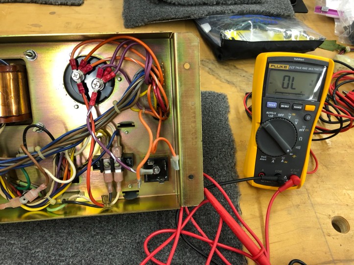
The last part of testing the power brick is actually plugging it in and checking voltages at the Molex connectors.
This site had very useful information: bitslicer
I used this graphic to create my test chart:
There are a number of YouTube videos on testing these – but I didn’t find a actual test plan written down. The one item you need to address to *actually* bench test the power brick is the 6 pin Molex connector. Its the connector between the power cord and the rest of the power supply and cabinet.
This connector is where the interlock switches terminate – these are the switches on the coin door and back panel that shut off the machine when you open them. I picked up a Molex connector to match and made a jumper block to simulate closed switches.
Jump pins 1-4 and 2-5 on the 6 pin Molex to power up the brick.
The 3 pin Molex on the power brick should have 120v AC on pins 1-3 – this powers the marquee light..
On the 15 pin connector:
DC Voltage Test with the meter
Pin 5 is negative
Pin 1 – 5 -> 10.6 vDC
Pin 2 – 5 -> 10.6 vDC
Pin 3 – 5 -> 10.6 vDC
AC Voltages
Pin 6 – 7 -> 36 vAC
Pin 8 – 9 -> 6.1 vAC
The remaining pins are specific to Centipede
Pin 10 – 11 -> 30 vAC
Pin 11 – 12 -> 30 vAC
Pin 10 – 12 -> 60 vAC
Pin 13 – 14 -> 30 vAC
Pin 14 – 15 -> 30 vAC
Pin 13 – 15 -> 60 vAC
One other item I learned is that the power brick is unregulated power – meaning the voltages can vary considerably.. But they all should be reasonably close to these numbers. Thankfully mine seems to be fine.
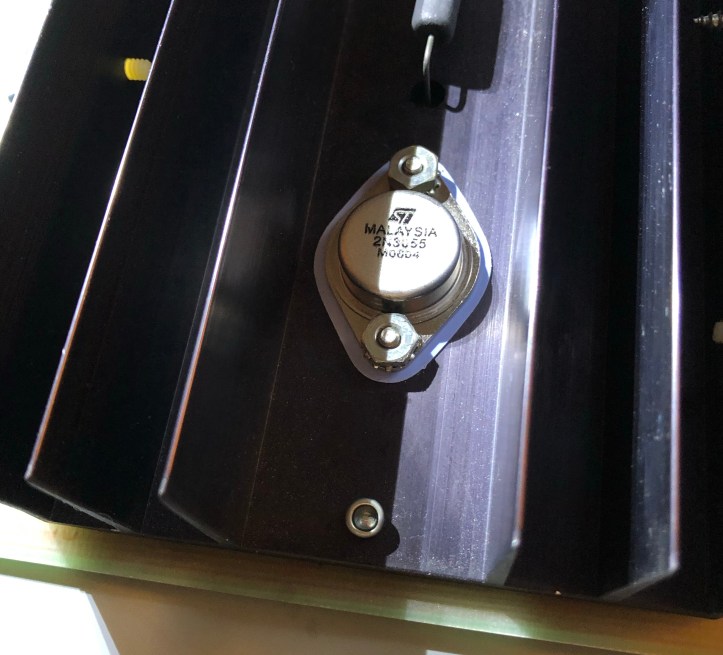
Most of the power ends up in the ARII board. Mine *seemed* to be working fine and the consensus is that the only component that you really should replace is this power transistor. The 2N3055. So I did…
There is some bench testing that can be done with this too. But I will likely need the harness from the cabinet to do any of that – or maybe I do the testing with the board in the cabinet. It doesn’t really make sense to build a bench harness unless I go buy more Atari machines…

More to come on the ARII board..

[…] Power Brick and ARII Board […]