
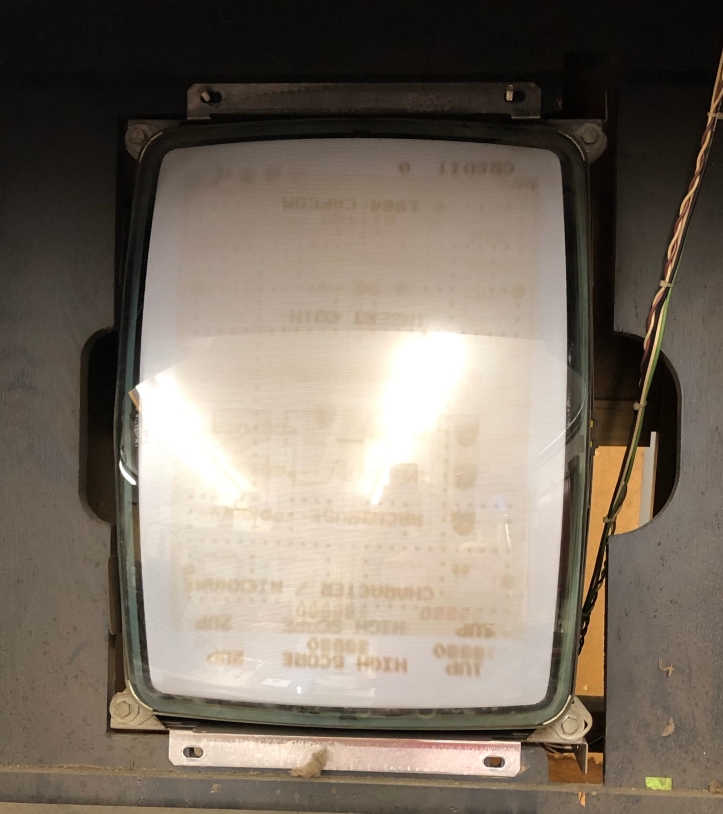
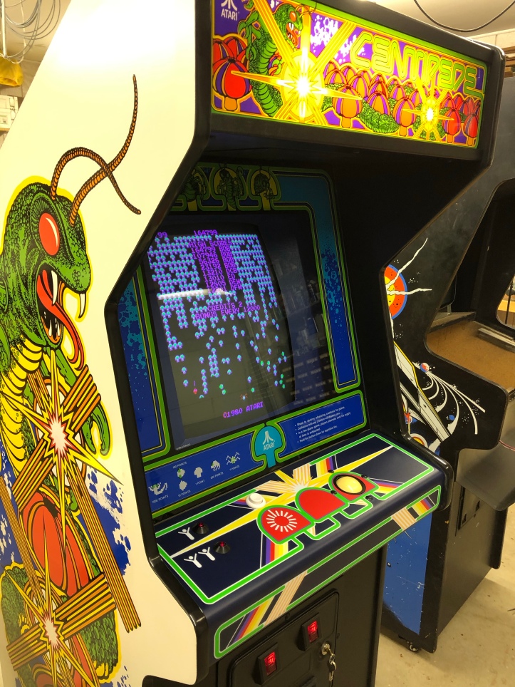
My machine has a working, but not very good looking CRT.
At some point someone did a tube swap.. There is upside down pacman burn in – and two sizes of it. Centipede had a swoop in the playfield from the top left down and parts were off the sides..
Research and friendly advice says – recap the monitor (replace all of the electrolytic capacitors) and swap the tube. People who restore arcade machines and monitors do this all the time – the wealth of information available is insane.
So – I’m not even going to attempt to come up with a *tutorial* so to speak. I am going to describe my CRT work from the perspective of a guy who has a reasonably good grasp of electronics, circuits and no fear of jumping into things. But this is my first one.
Not the nicest – but its what I have for now. I’ll have the chassis recapped and back together before I find a donor TV. Once I find a new CRT – I’ll replace it.
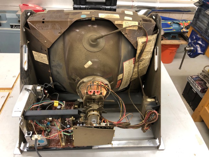
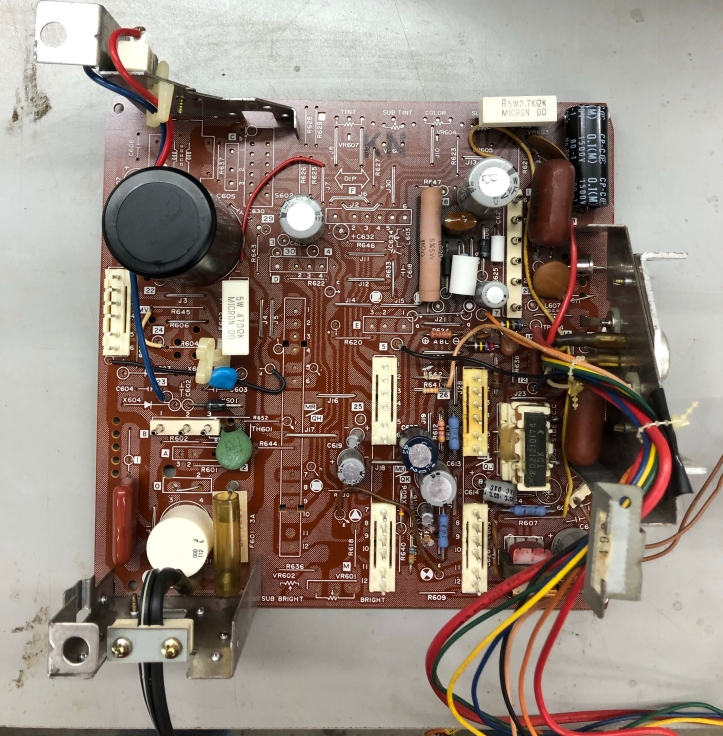
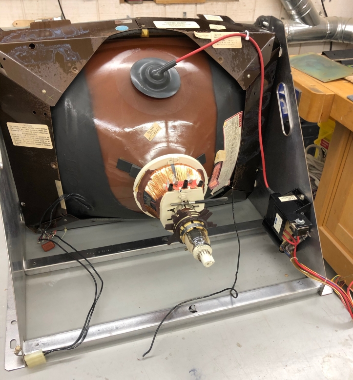
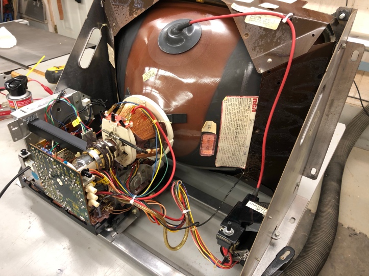
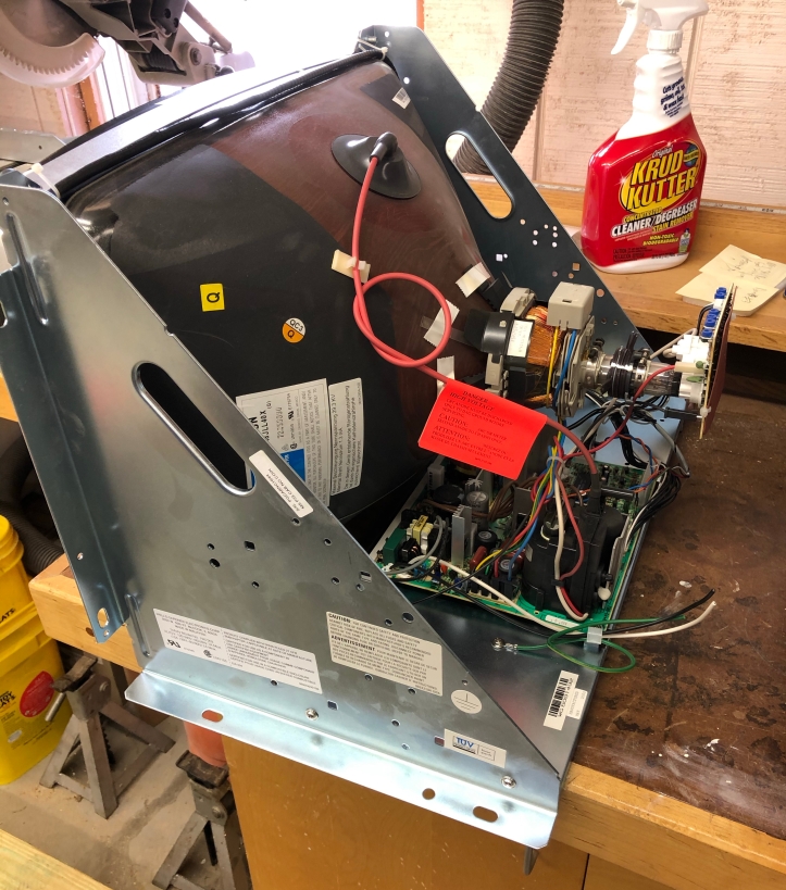
Here is the standard inside of the chassis – many years of dust and crud. I took pictures of everything with many closeups. These are pretty well documented – I downloaded the manual for this CRT – A Wells-Gardner K4600. There were a number of YouTube videos on this specific model. I can say – most of the people working on them didn’t care for the design..
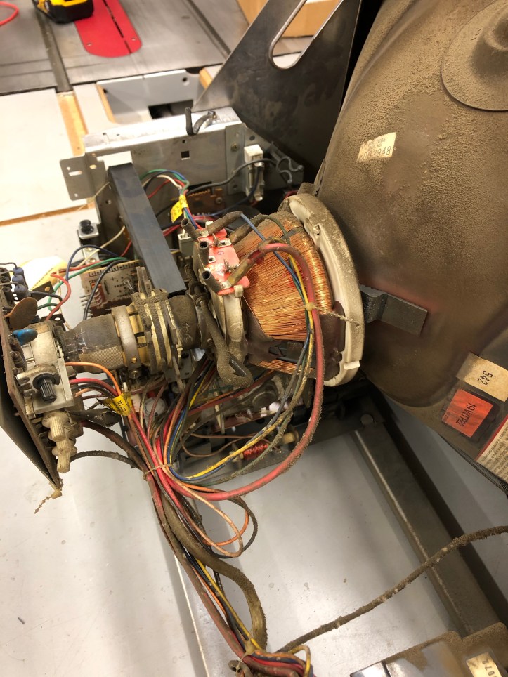
I’ll say I was quite nervous about the shock hazards inside the CRT. Every video out there shows you how to pop the anode (suction cup) off the CRT and drain any voltage using a screwdriver with a wire on. Once I understood that it is essentially discharging a big capacitor – it made more sense. Find some videos and pop that anode connector right off! Nothing to fear 😉
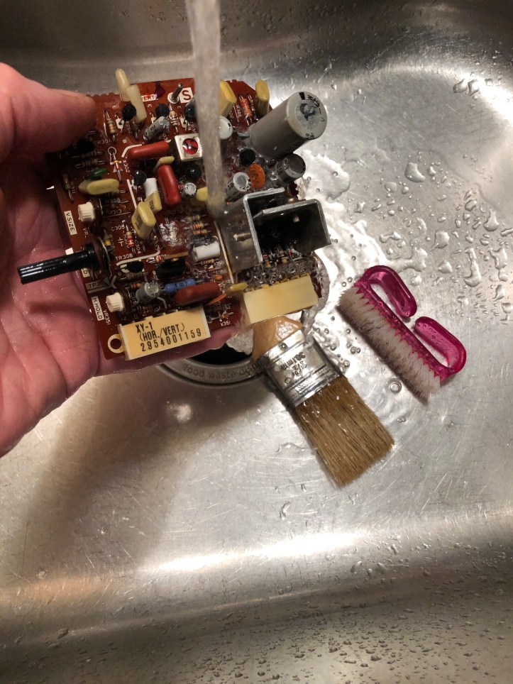
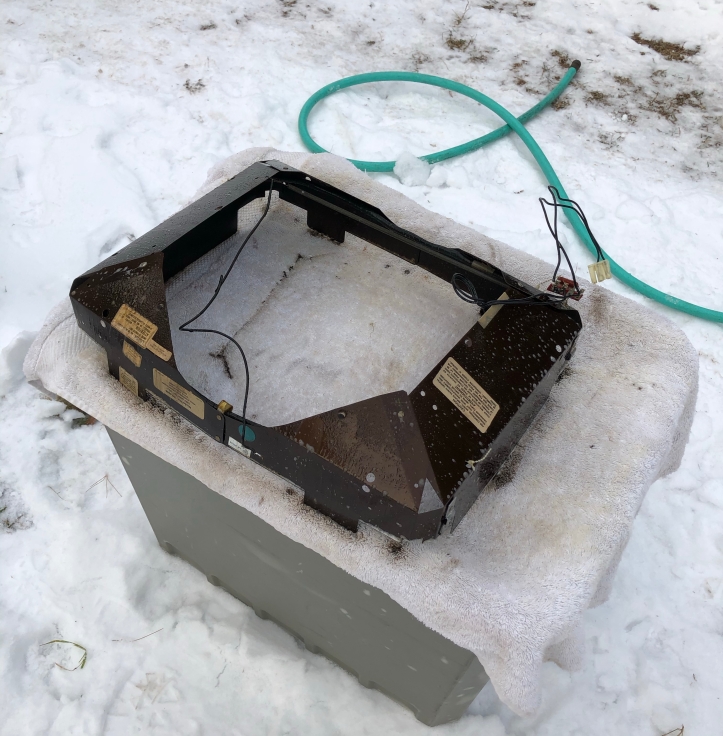
The next set of videos I watched were a bit astonishing.. Grab your CRT and give it a bath – literally! But after watching about 5-6 of them.. It wasn’t a scam. Most of them used Simple Green – which I just do not like the smell of. One guy used this stuff – Krud Kutter – available at Home Depot. He raved about it. I have to say – it really worked great cleaning up the boards. It will likely replace some of our other under-the-sink cleaners.
Here it all is – soak it down real good – let is set and wash away.. freaky..
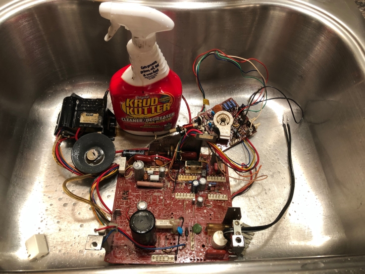
I used warm running water and a soft bristle paint brush to clean in and around components. Once you get past the not-common sense of washing the inside of a TV.. Use common sense and brush and clean – but be somewhat delicate with it all..
The hand brush I did use on the backside of the boards. It cleaned up 40 year old flux and other crud on the solder side of the board. Be careful as well if there are jumpers and resistors on the back.
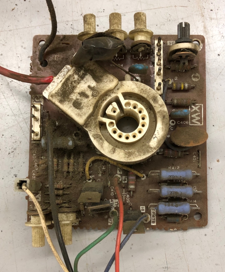
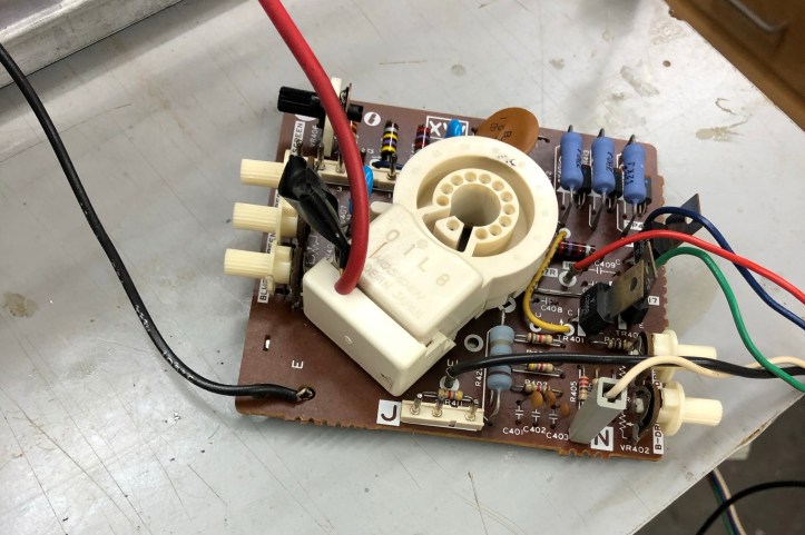
On the neck board – there is a black ground and the red wire soldered on under a white removable cap. It goes back to the flyback transformer. The black wire went to the ground wire on the tube. The simplest way to remove the neck board was to desolder them. Guys on the videos did it and it wasn’t a big deal.
Neck board before.
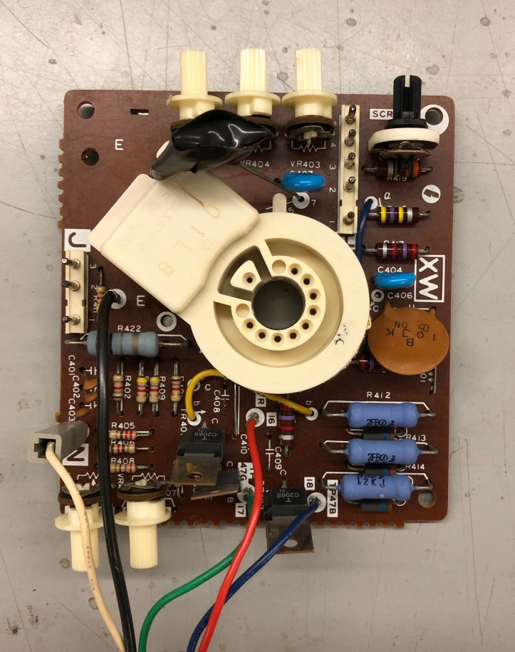
Neck board after..
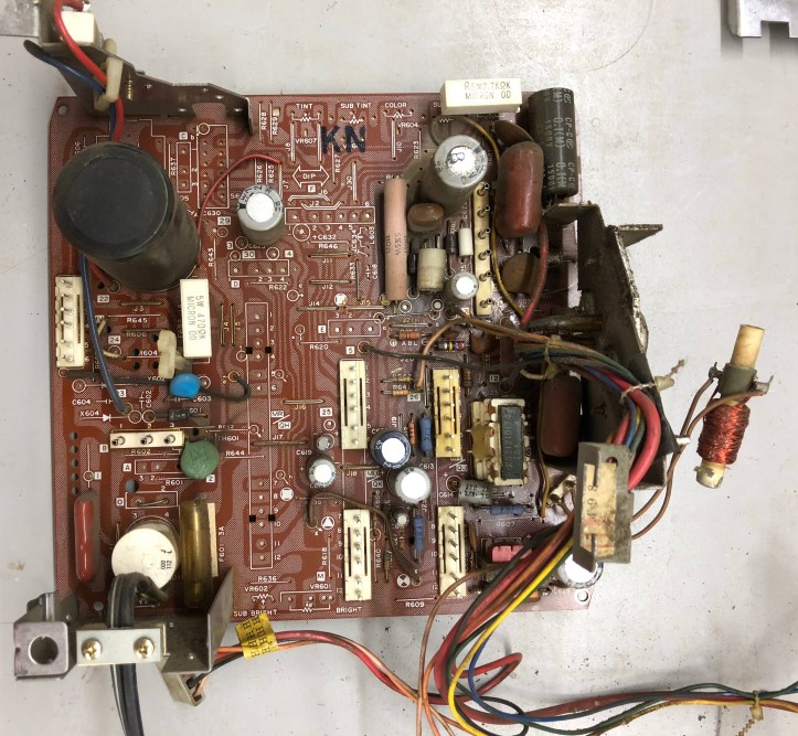
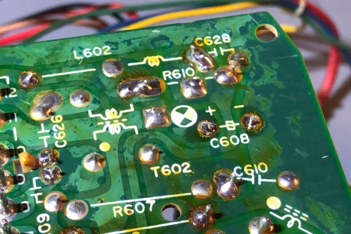
On the main board – there is one little delicate part to be aware of. The little red coil hanging out on the right. It can be removed from a holder that is part of the chassis. Some of the videos they desolder it. Just don’t break it!
Main board before:
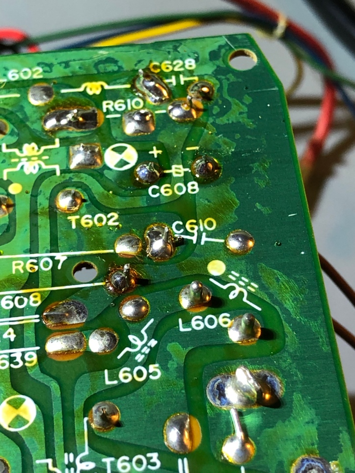
Main board after:
One thing in the “wash your TV videos” that I didn’t care for was they basically sat them out in the sun to dry.. (except for one guy).. USE COMPRESSED AIR! A compressor will blow out every little bit of water out of every little nook and cranny.. Do not blow apart your boards – again – be careful. Just use some air to get the water out.
Now – I love tools – I really love tools. There is nothing better than having the right tool for the job. Replacing all of the capacitors (and reflowing pins.. I will touch on that later) requires removing old solder. There are a bunch of ways to do it
- Heat the old part and push it through the board
- Use a solder wick and soak up the old stuff
- Use a bulb style solder removal tool
- Use a pump style removal tool.
or
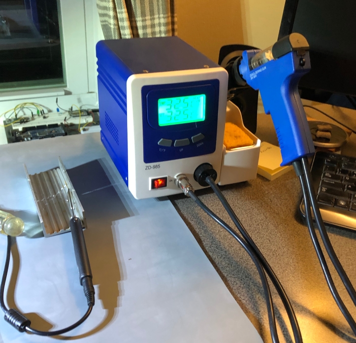
Get something that is fun and easy to use. I had a 5 day tangent just reading up and watching videos on these machines. As with anything else – you can spend as much as you want. But finding a sweet spot for the non-pro is where I was at. In the end – this was ~$140 and it really works very well. The vast majority of the caps just fell out of the board after sucking up the solder.. The others required a slight tug. ZD-985 Desoldering station.
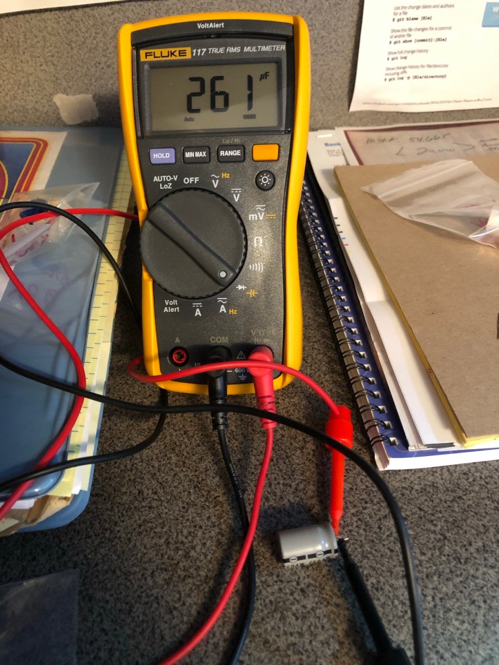
I have a descent multimeter – I think it was ~$50 at Home Depot when I got it. But while I was at it I decided to upgrade and demote my old one to my secondary tool set that stays at the camp. I now get why everyone likes the Fluke meters. You can feel the quality immediately when you pick it up..
While I was replacing the capacitors – I tested the old one coming out AND the new one going in. My reasoning was simple:
- Play with the new meter
- See if there were any *really bad* capacitors coming out
- Make sure I identified the correct one going in AND check its tolerance for comparison to the originals
Checking the caps coming out and going in also slowed me down and made sure I double and triple checked my work. Many of the caps coming out were off by 20%-30%. All of the new ones going in were within 10% and more often within 5%.
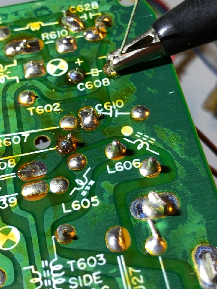
Here is the desoldering tool heating up a solder pad. Once it gets liquid (2-4 seconds) hit the trigger and it sucks it all up..
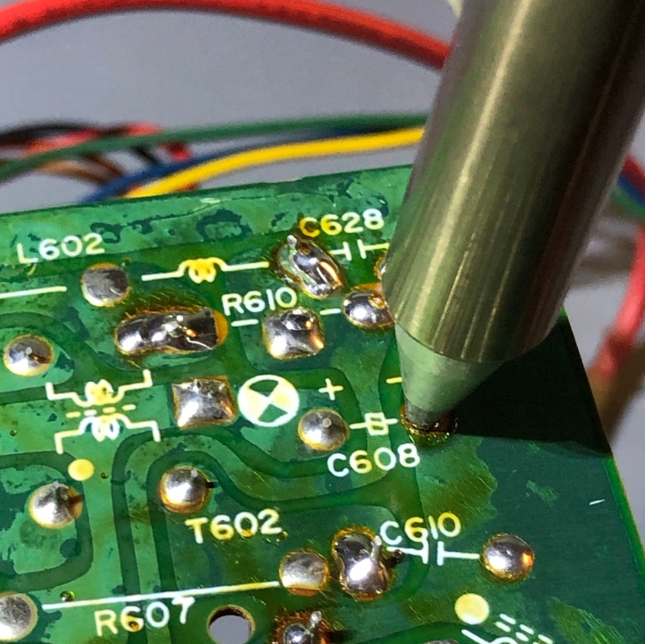
Both pads in C608 desoldered. Pops right out..
To get the new one in and keep it tight to the board – there are a bunch of ways to do it.
My first few I held one lead in place with an alligator clip, trimmed the other lead, soldered it and then clipped the remaining long lead and soldered it.
Eventually I just bent the leads outward just enough to hold the capacitor in place, then clipped and soldered. I’m going to hit this board again with water/cleaner to remove the flux.
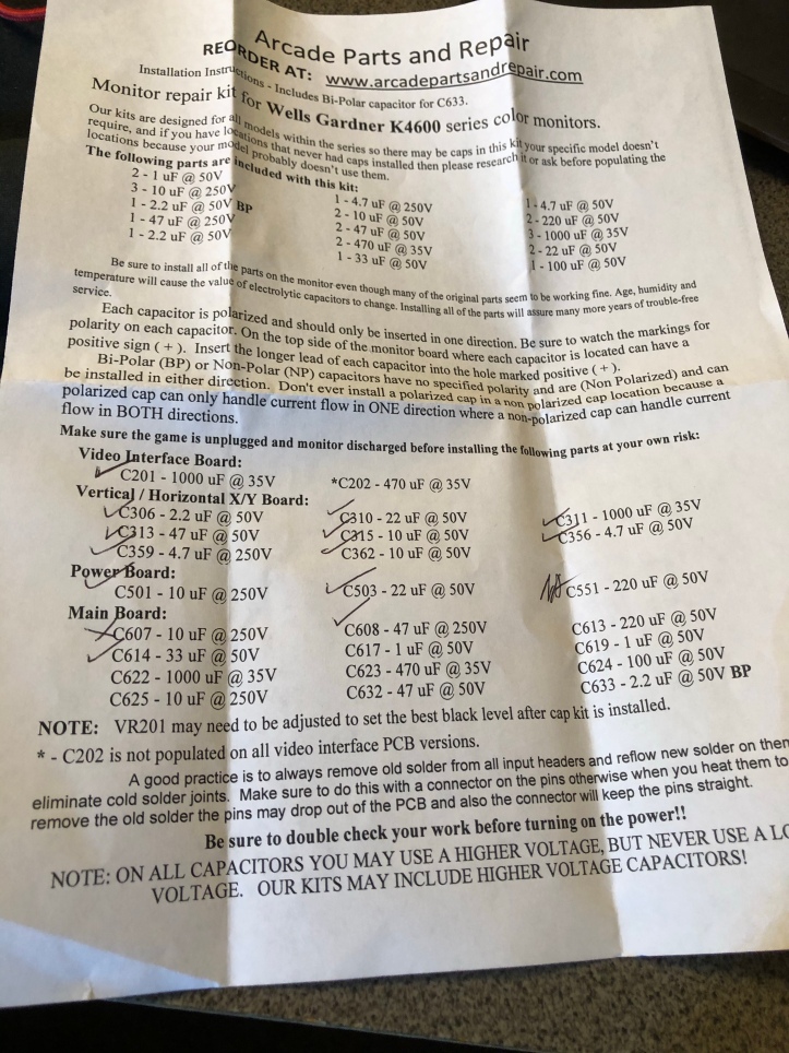
The recap kit these guys provided was complete. One thing you will bump into – not every board has every capacitor. I had about 5 left over. If your original board didn’t have it – then don’t add it! I used the sheet as a checklist and went through each one in order.
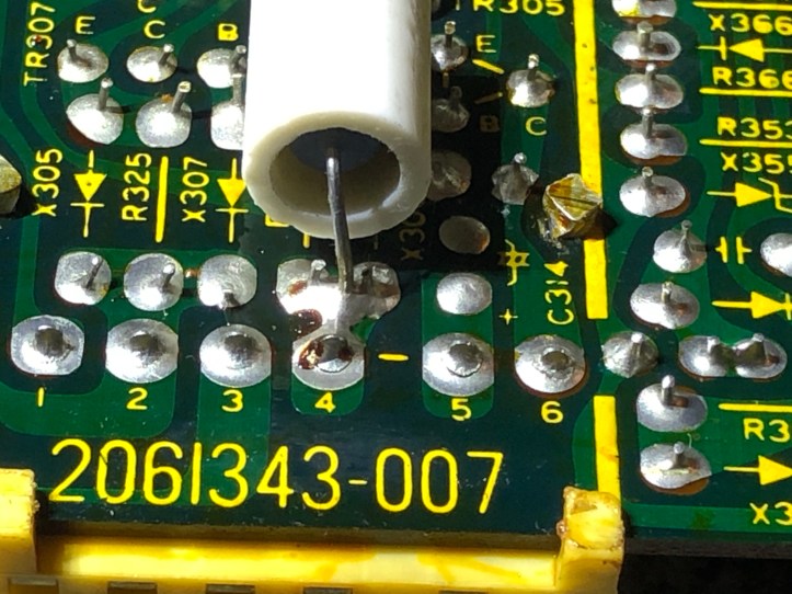
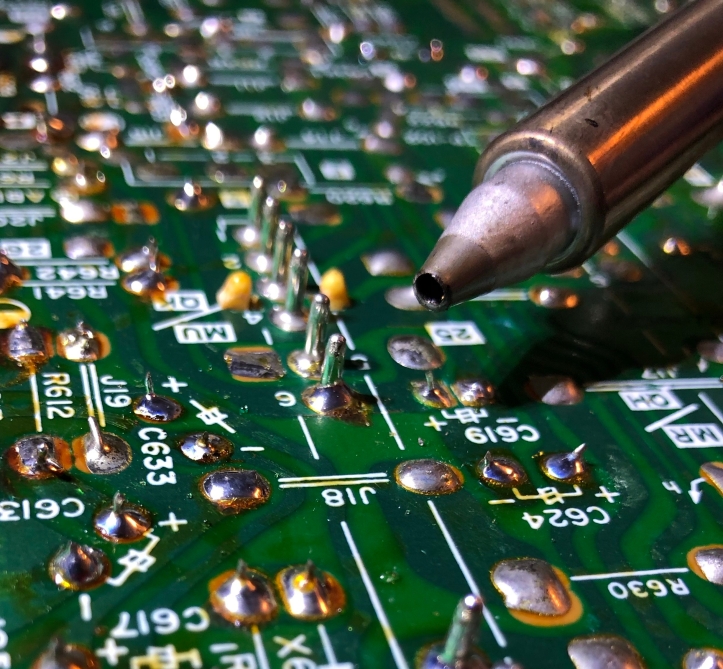
Pretty much every recapping video said – reflow all of the connector joints. Meaning any place there is an edge connector, the 40 year old solder is likely failing or will fail. At first glance I checked my boards and figured.. naaahh…. these joints are all good. Why fix what isn’t broken..
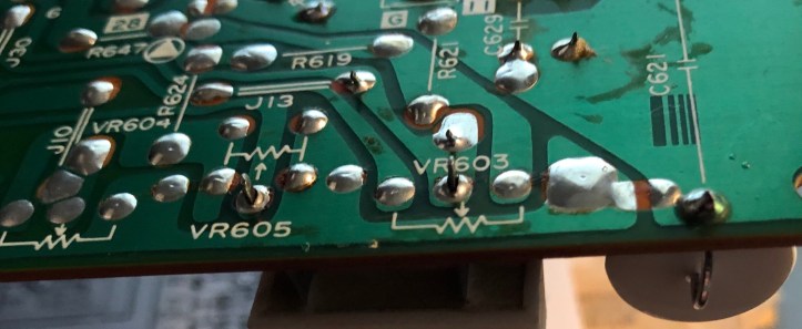
Upon further review I noticed a hair line at this connector. Took a pic and blew it up. The guys who do it all the time know what they are talking about. 4,5,6 show the failing joints very clearly. 1,2,3 certainly are suspect.
For reflowing the solder – some of the video guys just heated it up and added a little fresh. The guys who really seemed to be experts recommended REMOVING the solder and adding all fresh. This is the route I chose. The desoldering gun didn’t fit over these flat tabs, but it did remove a majority of the old solder.
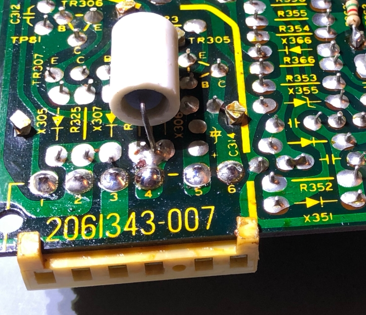
Reflowed..
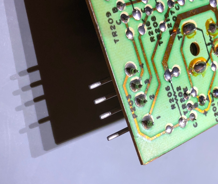
I was also warned about this style of connector. If you have a matching connector, use it to hold the pins so they do not fall out. I do not…
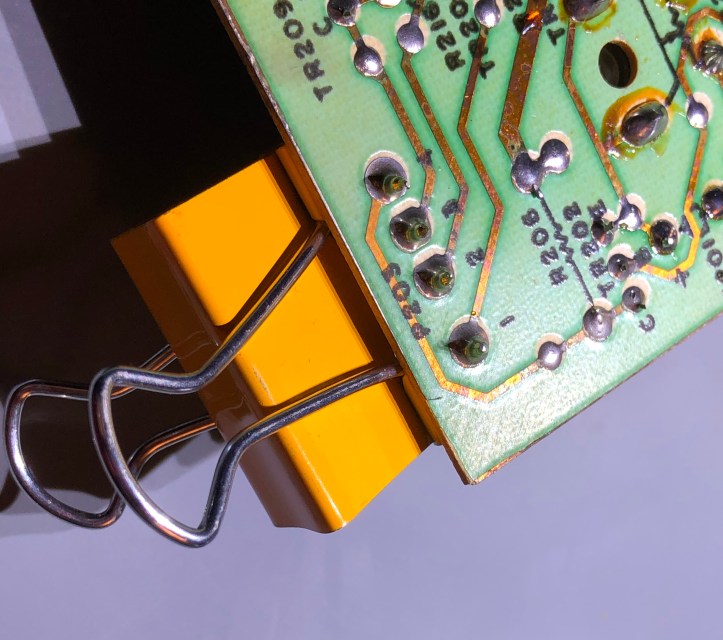
So I used a binder clip. Desolder and resolder 1 or 2 at a time so that there is a fixed pin to help hold the others steady.
There were some large diameter pins for the connectors in the center of the board. My gun came with 3 tips, small, medium and large. Medium is perfect for the caps. But large was too small to get over these pins so that I could desolder and reflow them. My solution was a 3/32″ drill bit to drill open the hole in the tip enough to get over the pin AND allow solder to be sucked up around it. My large tip is now XL.
Here is a board all recapped.
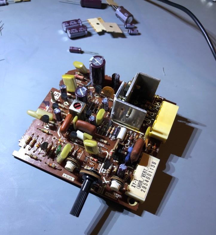
I’ve finished all of the recapping and reflowing of the pins.
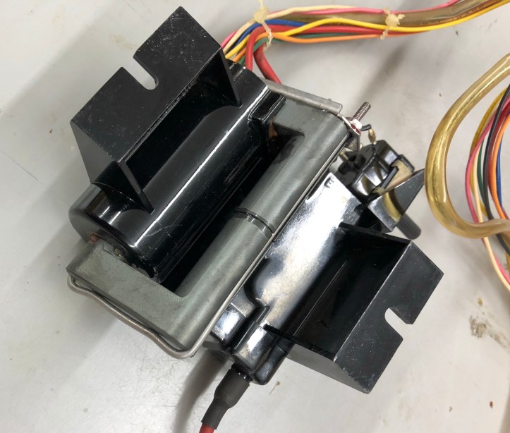
I did run into what I would think would be a rare issue – there is a U-bolt in the flyback transformer that holds a ferrite core in place. Mine was broken – I’m guessing some metal fatigue.
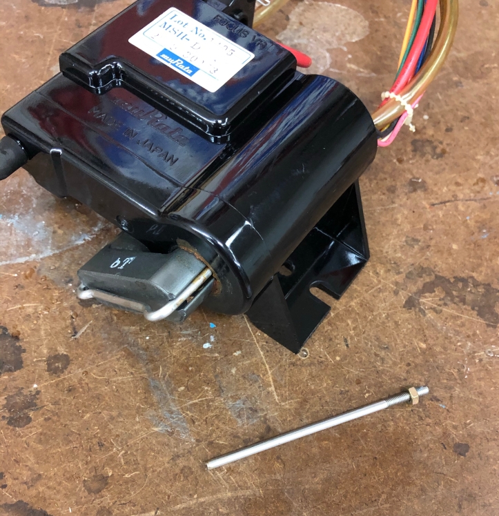
It turned out to be a bit easier to repair than I thought.
First was a trip to the hardware store – I determined the original threading was metric (3mm). I also checked the original and it was non-magnetic and hard to cut. That tells me it was stainless steel (vs. aluminum)
I picked up 3/32″ stainless rod, a 4-40 thread tap and a couple of small nuts and washers. Next I bent the wire with a tool I had for crimping ducts and a couple of needle nose pliers.
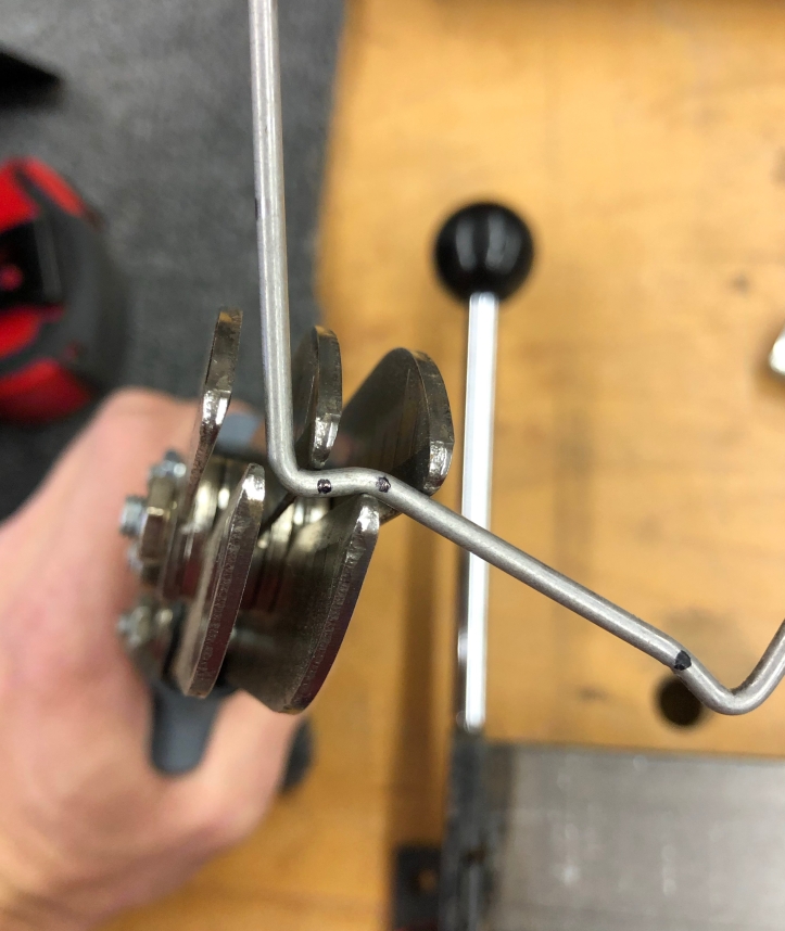
Once I got it to shape I clamped it in the vice and tapped the 4-40 threads onto my replacement. Little 4-40 die cost $5
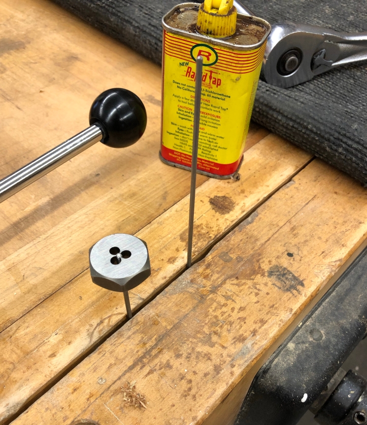
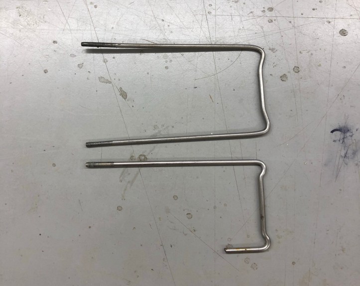
Fits perfect and is nice and snug.
Down to final cleaning and reassembly
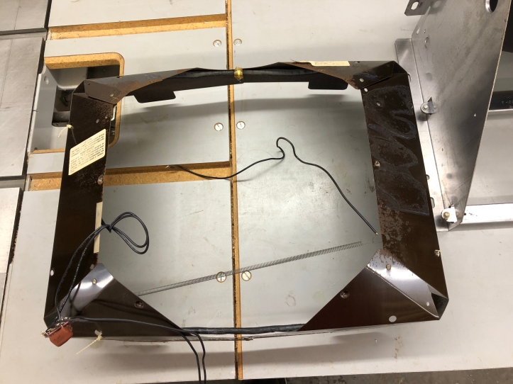
The K4600 has a metal shield that comes off real easy with 4 screws. The shield has the degaussing coil attached. Cleaner and the paint brush did a nice job. A couple of the original stickers were laying around inside the cabinet. I’m going to re-stick them later.
More cleaner and a hose.. I didn’t realize it the first couple of times I moved the chassis – the oval holes on the sheet metal sides are carrying handles. Just in case this is your first time too..
Metal degaussing shield cleaned up.
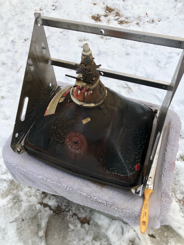
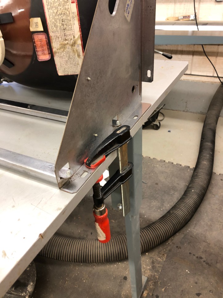
The CRT is very front heavy. Clamp it to the bench – I would not consider this optional.
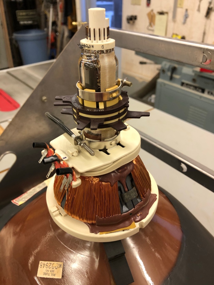
Like the day it was made. I spent about 15 minutes on the tube with the compressor blowing air under the yoke and down the windings to push out any remaining water. If a little dribble came out – the air would dry it.
First up was the degaussing shield and the flyback transformer.
After that I reattached the ground wire and the red wire (that was from the flyback to the neckboard.
Add the main PCB and daughter cards
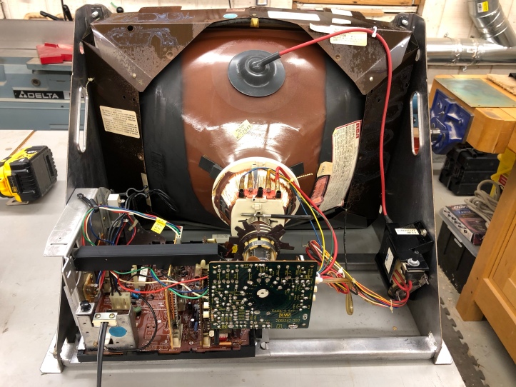
This CRT is ready to get bench tested and adjusted. One thing I would do differently on the next one.
Here and there – there will be a single little wire that you pull off (like a ground line) or pop off a screw to unhook something. I took a bunch of *before* pictures but not so many afters. I spent a little extra time trying to figure out – where did this attach?
So – If you are going to pull off a specific wire – take a pic of it on and right after that show it disconnected next to where you pulled it off.. That way the pics are beside each other in your phone. (or camera? does anyone use cameras anymore?)
I found all of the right pics – but there were not next to each other and a before/after of the wire in the same spot would have helped.
Same for zip ties. Show the before and cut tie so you know where it went.. Just for the sake of completeness. On this chassis they use a couple of ties just to hold boards in place.
Bench Testing the Wells Gardner K4600
The good news – everything worked exactly as before!
The bad news – everything worked exactly as before…
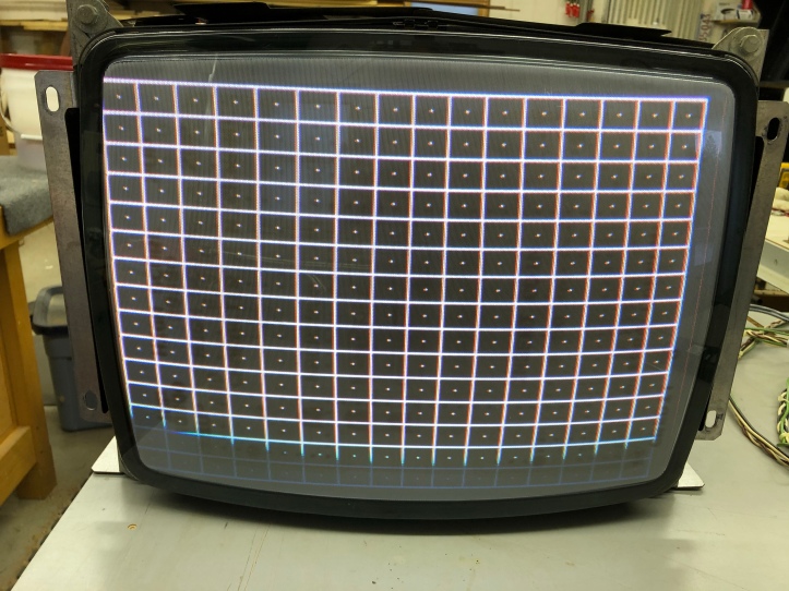
Screen is too far to the left and a little too far down. It also has distortion along the sides of the grid. The CraftyMech Test Pattern Generator has been very useful in learning about monitors. When using the Centipede PCB – I was getting the same distortion and horizontal centering issue.
I’ve also been hunting for a donor TV to replace this badly burned in screen. So far no luck. I’ve come across many TV’s with the CR31 neck (newer TV’s) but none with the CR23 neck to match the K4600 tube. It won’t fix the distortion – but having upside down Pacman burn-in on Centipede is just wrong. The search continues.
The amount of information available is almost overwhelming. KLOV/Arcade Museum is the place to go to get all of the manuals, schematics and access to many people who have worked on these CRT’s. The tricky part is knowing how to search using the correct terms or ask a question without someone telling you its been answered 50 times already and “USE THE SEARCH!“. Yet another vocabulary to learn…
I’ve been messing with the CRT for a couple weeks while figuring it and the terminology out.
Here are a few items that I’ve picked up:
No matter how many times you have looked at the board – look again.. You may still have missed something. Maybe give each component a wiggle or magnified inspection.
On VR605 and VR603 (which is one big power resistor on the other side) – after taking the board in/out 4-5 times – the cold solder joints gave out. I resoldered them – but it did’t correct the issues.
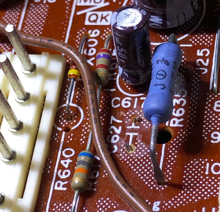
Another one I just found: C627 is completely missing. I checked the *before* pictures and it wasn’t there before I washed everything – so at least it wasn’t self induced. This tiny speck of a capacitor is part of the horizontal sync circuit – maybe it will get rid of some of the distortion? The local electronics store did not stock these – but Amazon.com did – go figure. It will be here in a couple of days and I’ll test again.
I’ve been checking components in place with the meter – diodes, transistors, resistors and capacitors. If any seemed suspect – I’d pop them out and bench test them.. No real smoking guns as far as each component goes. It’s possible there is a weak part in there someplace. I found you get a feel for how they test on the board.
Anther tip on these from KLOV:
There is a horizontal width adjustment coil that is exceptionally delicate and not very replaceable. It pops in/out of this little holder. The downside is just trying to pop it in/out of the holder is the best way to break the coil and it has to come out to work on the main board. I found a suggestion that said to drill out the rivets for the mounting bracket and replace them with small bolts. Great idea.
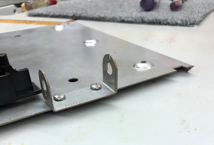
Now when I pull it apart – the bracket stays with the coil with less risk of destruction. BTW – this coil adjusts with a small hex wrench that turns ‘something’ inside the coil. It made the screen shift horizontally a tiny bit, but didn’t have much of an effect.
One other oddity that I’ve run into:
On the TPG – you can turn off each gun independently with a dip switch. If I turn off red switch – the whole screen goes red (it *should* just turn red off – not full on). It does the same for green and blue. CraftyMech says that it should not work this way and maybe the signal line is floating. I haven’t determined if this is an issue with my CRT or if it is something that is weird about the K4600. In the short term – I’ll turn off the guns with the controls on the neck board.

After my capacitor shows up (and likely makes no difference) I’m going to try a couple more things:
I picked up used K4600 chassis boards on KLOV for $40. I’ll swap the interface board and the XY board to see if anything changes and maybe I can localize the issues to a particular board.
There is also good information on later model K4600’s that have a horizontal centering adjustment pot on the interface card. Most models do not have it (including mine) – but it looks like I can swap a resistor, add a resistor and a couple of jumpers on the main PCB to *enable* the mod. This is supposed to let the P317 interface card adjust the horizontal centering.
But I don’t have a P317: It looks like the horizontal adjustment part of the circuit has nothing to do with the actual P317 card. I plan to experiment and see if I can just add the mod to the main PCB. If it works – I *may* be the first person to have done it. Those parts are on order too.. It will be a good test and I can’t fry anything by trying.
Back to fixing the CRT
I took a break from messing the the K4600 to build an Bench isolation power supply
It will make working on this and any future CRT’s much easier to set up/tear down.
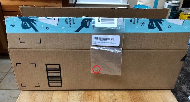
My teeny speck of a capacitor arrived – it came very well packed in this box. Not sure what is worse – that the box is stupid big or that a human taped it inside, filled it will air pillows and sent it on its way..
I put in on the main PCB (C627) – it made no difference to the horizontal centering circuit.
Now to try something that I do not think has been done this way before. The K4600 had many revisions and model numbers. Each with different schematics, components, interface cards, etc. The later releases of the PCB supported the P317/P318 interface cards which have a horizontal centering pot. I found a few references on KLOV that detailed the “Horizontal Centering Mod” for the K4600. It took a couple hours to decipher a few threads and consolidate all of the information. I’ll assume if you got this far – you have recapped your boards and have the schematics. The centering mod is for K4600’s where you cannot get the screen to move far enough left or right (obviously).
Basically here is the Horizontal Centering Mod summarized from other threads:
On your main PCB: (mine is a K4606 just for reference)
- Replace resistor R635 with a 6.8K 1/2W resistor
- Remove jumper J19 and put a 6.8K 1/2W resistor in its place
- If you HAVE a P317/P318 interface card
- Add a jumper wire on the back side of the board from pin 7 of the XY board connector to pin 1 of the Interface board connector (P302 pin 7 –> P201 pin 1)
This connects one side of R635 to P201 – you can see it if you follow the trace. - Add a jumper wire from the opposite side of R635 to pin 2 of the interface board connector. (R635 –> P201 pin 2)
- Add a jumper wire on the back side of the board from pin 7 of the XY board connector to pin 1 of the Interface board connector (P302 pin 7 –> P201 pin 1)
- The horizontal centering pot on the P317/318 interface card should now work with your older main PCB.
After printing out both the P306 and P317 interface card schematics – it quickly became clear that the ‘Horizontal Centering Pot’ had no interaction with the actual P317 board. It just happens to be on it (I’m guessing because it was easier to do a mod on the much smaller board than the main PCB when they were being manufactured)
If you DO NOT HAVE a P317 or P318 interface board – give this a try.
Here is a schematic snippet (hopefully this is OK) – Copied from KLOV.
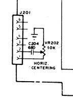
On the edge of my PCB there are many unused holes – I took a small 10K pot, bent a single leg down and soldered it to the ground trace on the perimeter of the PCB. Not perfect – but it holds it in place on the single leg.
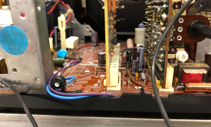
Steps for mod:
- Solder one leg of the pot through an unused hole into the ground trace on the main PCB.
- On the center wiper pin – solder a 680pF Z5F (C204) capacitor.
- Add a jumper wire on the back side of the board from pin 7 of the XY board connector to the second bottom leg of the pot opposite the ground leg.
This connects one side of R635 to this leg. (P302 pin 7 –> pot leg not soldered through the board) - Add a jumper wire from the opposite side of R635 on the back of the PCB to the capacitor on the wiper on the pot.
- This bypasses needing a P317/8 card completely and gives you the ability to center horizontally.
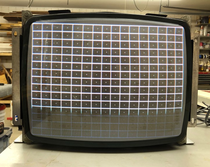
The furthest right I could get this screen before was this: (not sure how the get an iPhone to scan at a different rate than the screen – the bottom is not dim as shown)
With the centering mod:
This CRT still has a way to go. For starters I’ve been hunting for a few weeks for a donor TV – no joy yet. I’ll experiment with convergence/purity on this one to get a feel for it. I have plenty of distortion and the tube is badly burned in. I’m not certain if the distortion is 100% a tuning issue or is having a crappy tube contributing to the distortion problem.
Two other things happened as a result of the mod:
- L351 – the Horizontal Oscillator adjustment (seems) to have become way more responsive. Before the mod it either held sync or didn’t. Now it helped with centering and gave me some ‘range’ to work with.
- The Horizontal size coil (L702) also started doing more – I was able to make better adjustments. Previously I could get the screen to move maybe 1/4 inch.
I could not have tried any of this without all of the information available on KLOV and the work done by others. Hopefully someone will find this useful.
Its been a while since I’ve updated this entry.. I’ve made incremental progress on the K4600 monitor.
I picked up a dead chassis so that I could compare and potentially swap components, etc.
One thought I was having was that the neck board was giving me issues in general. Earlier in this thread I mentioned to check, double check and check again for broken off parts. Turns out there were 3 tiny capacitors on the neck board broken off.
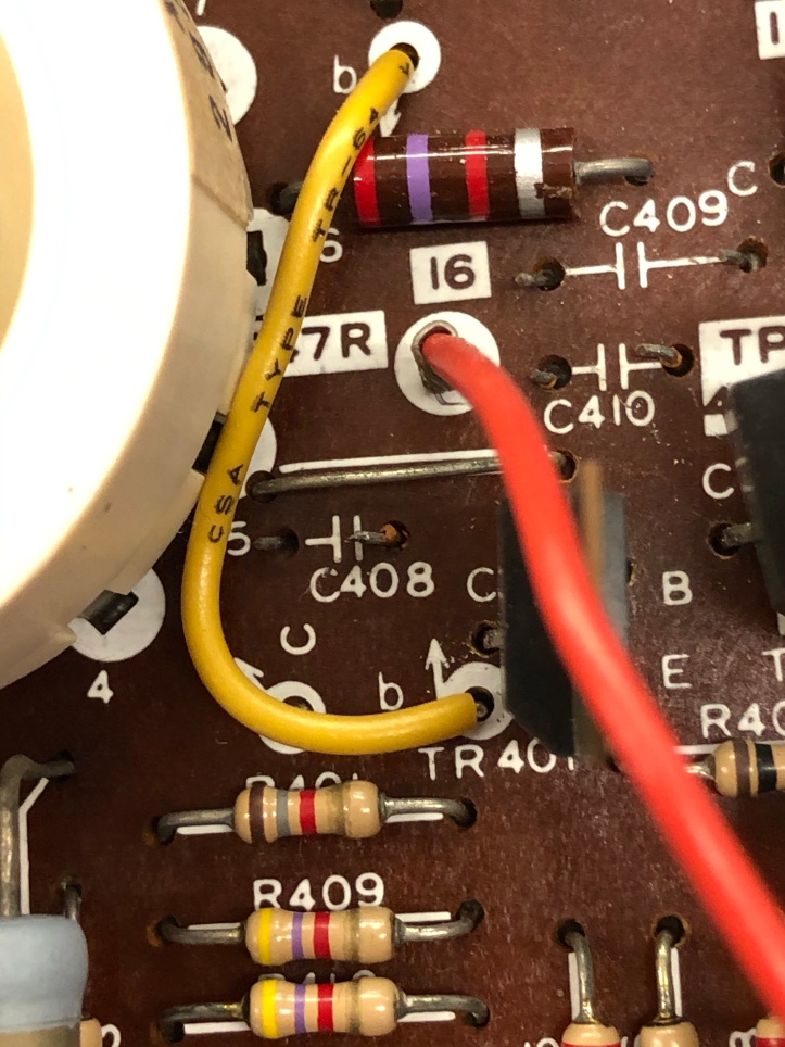
Look at C408, C409, C410. These ones are not even shown on the schematic that I have, but they are on the parts list. I swapped the neck boards and it appeared a little color bleeding went away.. But nothing significant.
On the inability to shut off color guns with the TPG, I figured out why that was an issue. My K4600 uses the P305 interface card which doesn’t have pull down resistors like nearly all of the other cards:


You can see the 3 resistors connected to the RGB pins 1,2,3 on the right. I added the resistors to my card so that I can turn off the individual guns. When I was turning off the guns with the TPG, the voltage was floating and the guns just made the entire screen the color I was turning off. One more thing learned…
During this Learning to fix crt phase – I’ve watched many Randy Fromm videos. He has a book – Randy Fromm’s Big Blue Book of Really Great Technical Information that I picked up..
One thing I thought I understood – but not well enough was this:
The alignment of the convergence rings on the neck of the tube.
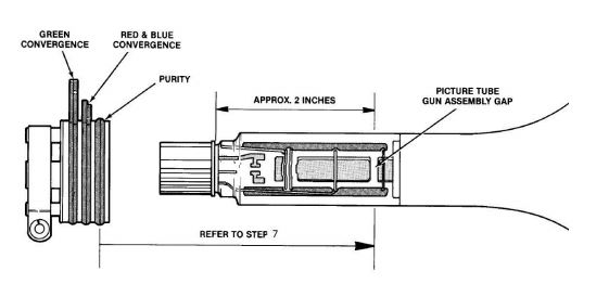
My swapped tube had an all in one unit of yoke and rings. I had to use the K4600 yoke and rings. Turns out the geometry of the swapped tube didn’t allow for the proper alignment The gun gap was in a position that the 2 part yoke/ring combination would not line up vs the one part original. I had a LOT of practice aligning and un-alignable configuration..
I have another donor tube to experiment with – I’m pretty sure I can get them lined up and I’ll try again..
All that said – this chassis probably was not the original since it had Pacman and 1942 burned into the tube. I’ve been watching Facebook Marketplace and came across a guy who was selling 3 arcade monitors.
One of which is impossible to believe:
This is a brand new, never used, K7200. Manufactured in 2003. If you look at the power wires – they have never seen a connector. It came as is – I’m guessing the guy who sold it to me took it out of a box or bag or something.. I did a quick test on the TPG to make sure it fired up and finished the monitor portion of the Centipede machine.
My wife tells me I lead a charmed life when this sort of thing happens.. I’m not disagreeing on this one..

[…] Working on the CRT […]
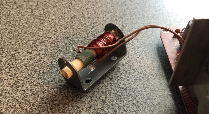
What I do for the K4600 width coil is snip and strip the two wires. Crimp on .062 sockets and pinch them a bit. Also put some heat shrink over the crimped sockets. Then the sockets fit snug on the header pins.
…Then any time I need to work on the K4600 main board, slip off the sockets and leave the width coil with the frame.
I like that – I haven’t touched a 4600 in a while – But I will certainly do that when the time comes.