
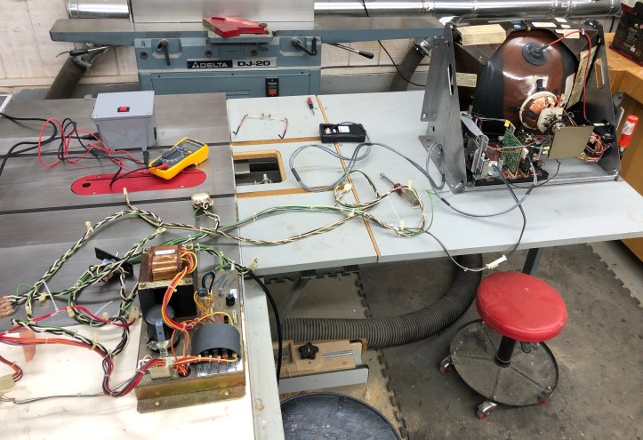
Working on this CRT (and potentially future ones) was becoming annoying..
Every time I wanted to ‘try’ something – I would break out the Atari Power brick and the Centipede wiring harness, plug it all together and use a Molex connector as a power switch on the Atari brick. It all works fine – but at some point I’m going to want to put all that stuff back in the cabinet and I suspect the CRT will still be on the bench.
Time for a bench power supply for the CRT. These have been done a number of different ways – but here’s mine.
There isn’t too much to it actually – the key is having an isolation transformer (mine is an Autobot) to provide the power for the CRT. Much has been written on isolation transformers for powering electronics. In a nutshell – the transformer is a 1:1 ratio transformer that provides the voltage to the CRT while not allowing that circuit to have a path back to earth ground.
The Atari power brick has an AC line filter which blocks electric noise (it seems). No reason not to do the same.
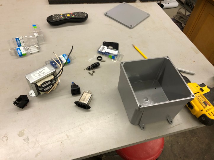
Here are the parts I used:
- Isolation transformer
- 6 x 6 x 4 – Junction box from Home Depot
- Panel Mount EMI Filter/Socket
- DPST illuminated rocker switch
- Panel mount fuse holder
- Panel mount power outlet
- 3A fuse
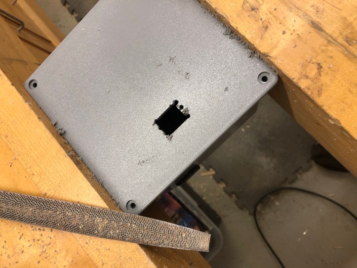
If there is a simple way to make square holes in plastic – I haven’t found it. Basically I draw an outline slightly smaller than the actual hole I need, use a drill to remove the center and a file to sneak up on the actual hole size needed. Some people use a hot knife or blade type soldering tip. But the last step is the same – use a file to sneak up on the final hole.
If you have a jigsaw – you can use the blade to speed up the ‘filing’ process. But its all hand work to make them fit.
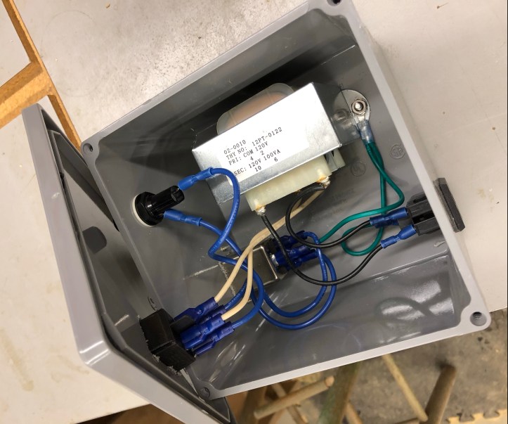
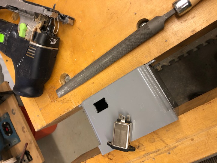
Skipping ahead – here is the completed power supply. Power inlet/EMI filter on the bottom left, transformer bolted to the bottom, fuse holder on the side and power switch on the top.
Wiring:
- Earth ground goes straight through to the power outlet and is grounded to the isolation transformer case. The Atari wiring harness is set up this exact way. (green wire)
- Hot wire from the power input goes through the fuse holder and then to the power switch.
- Neutral wire from power input goes to the power switch.
- Both primary wires from the transformer connect to the power switch. (white wires)
- Both secondary wires from the transformer connect to the power outlet. (black wires)
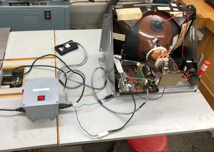
Completed power supply:
Any standard power cord can be used to plug this into the wall.
On the output side for the monitor:
Cut the female end off another power cord and add a Molex connector that matches your monitor (mine is K4600). For the earth ground – I added an alligator clip. The Atari configuration has the chassis connected to earth ground – so that’s what I’m doing. The nice thing about this is if/when I get different chassis – I can make up another power cord for that chassis and plug it into the power supply.
The rocker switch has a build in LED and turns on when the switch is on. This is so much easier.

[…] Bench Isolation Power Supply […]
[…] Bench Isolation Power Supply […]