This one was a bit more of a challenge than I expected…
My new Joust has a switcher. Not what I wanted for this cabinet. It will be repurposed. The good news is they didn’t hack up the harness to install it. A pin connector was created that went from the switcher to the wiring harness Molex so nothing on the original harness side got ruined. They did use a couple of crimp wire taps to jump the isolation transformer monitor connections to power the switcher. Those will get cut out and I’ll re-terminate that connection. It could have been much worse.

I’ve rebuilt a few power supply boards and its a very methodical process. First – take pictures of everything from all angles just in case you forget where it all goes . Start at the power cord and work your way through the EMI filter, transformer, regulator board, etc.
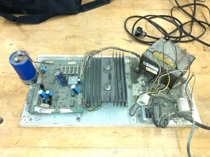
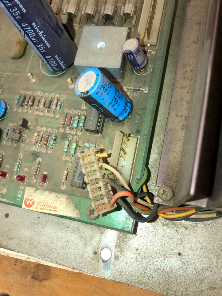
Whoever had this prior obviously had issues and finally gave up and installed the switcher. What jumped out first was the filter capacitor with two wires, cross connected and pretty tight like its keeping it from falling off… hmmm… that can’t be right..
The board has a total of 9 capacitors – 5 of them are axial and should have been radial. One fuse was blown, 3 of the remaining 4 were flat out the wrong ones.
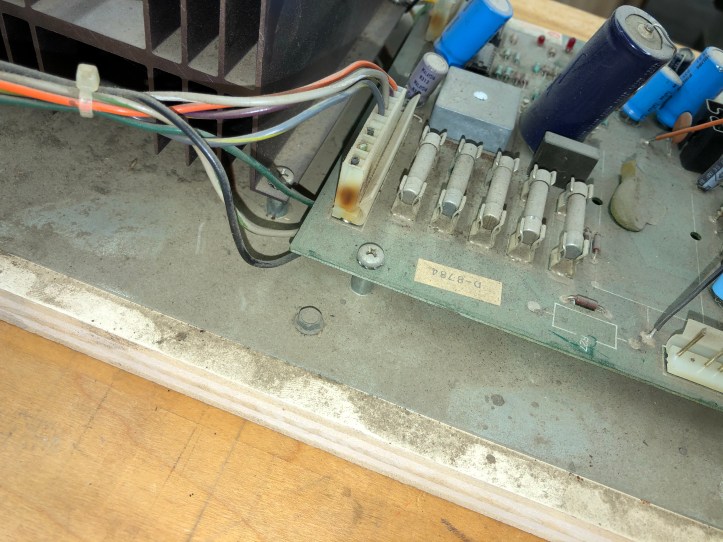
Connector a little toasty? No problem – cut the wire and solder it to the pin on the bottom side of the board … ughh.
This one too….
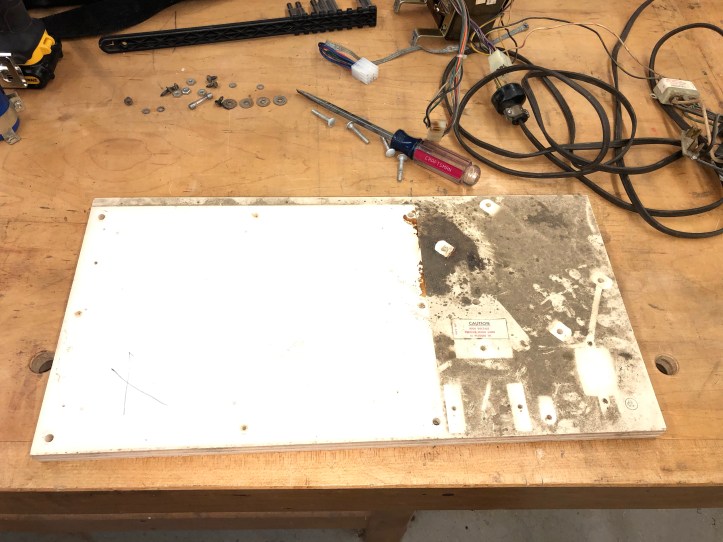
I expected the mounting panel to be in much worse condition – but it was pretty nice. Just a little cleanup needed. It had some inspection dates stamped on it – so it stays.

This transformation (a little pun intended) took a while.. Not the cleanup so much – but it turns out this combination of transformer and power supply board does not seem to have a schematic available.
The Joust upright has a different transformer than the cocktail:
Williams Electronics 5610-09658-00
Connections 1-8 are on the primary side and connections 9-20 are on the secondary.
The cocktail transformer is a:
Williams Electronics 5610-09629-00
Connections 1-6 are on the primary side and connections 7-15 on the secondary.
The upright as a 15 pin Molex connector and the cocktail has a 12 Pin.
Note: The above pic shows a 15 pin Molex on the cocktail for now. I’m ordering a 12 pin replacement ONLY because the original had it.. call me crazy. The original 12 pin was burned up which I’m sure replaced the original IDC connector which was probably burned up.
The 12 Pin Molex (4P1) connects to the D-8784 regulator board at 4J1 and leaves pins 13,14,15 open/unused.
I cleaned everything up, replaced the original power cord started looking for the correct schematic to test voltages on the transformer.. but I’m not sure it exists. I finally found reference to my situation on a thread on KLOV which at least pointed me in the right direction.
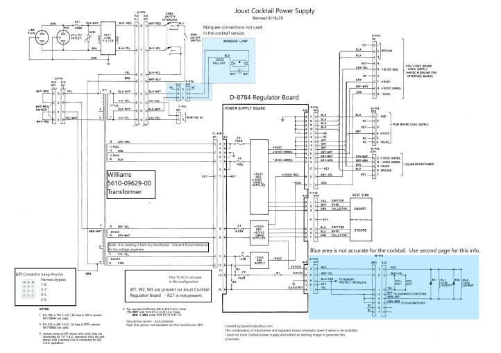
In the end – I found a close enough schematic that I went in and used MSPaint to create my Williams/Joust Cocktail schematic. The key is the 5610-09629-00 transformer and the D-8784 combination which if it exists in schematic form, I can’t find it.
My Joust Cocktail Power Supply custom schematic:
Downloads: Joust Cocktail power supply-bp
I added info about the W1, W2, W3 jumpers and updated all of the pin numbers on the transformer and corrected the wire colors (well – they match mine). I verified the voltages off the windings, etc. The transformer is similar to – just not the same as the upright. I also added the jumper config for the interlock connector for bench testing.
Note: Windings 11-12 on my transformer read 9.6vac w/o load. Well below the 11.5vac on the schematic for the other transformer. I checked my upright transformer and it reads the same 9.6vac. Maybe the upright schematic is a little off??
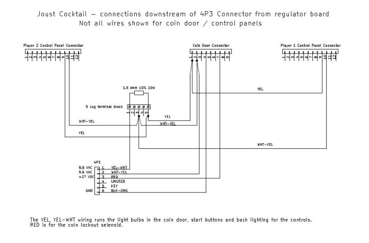
The schematic above was originally from the upright Joust. The connector at 4P3 is different in the cocktail in how the wiring is used. The AC power from the 9.6v goes through a 1.5ohm 10W resistor and reads 5.3v at the bulb(s).


This part of the circuit is confusing as compared to the upright so I created a schematic for wires downstream of 4P3 just to document it better. It’s included with the PDF above.
Not sure why cocktails have different configurations than uprights. Anyone with a Williams cocktail may be able to use this.
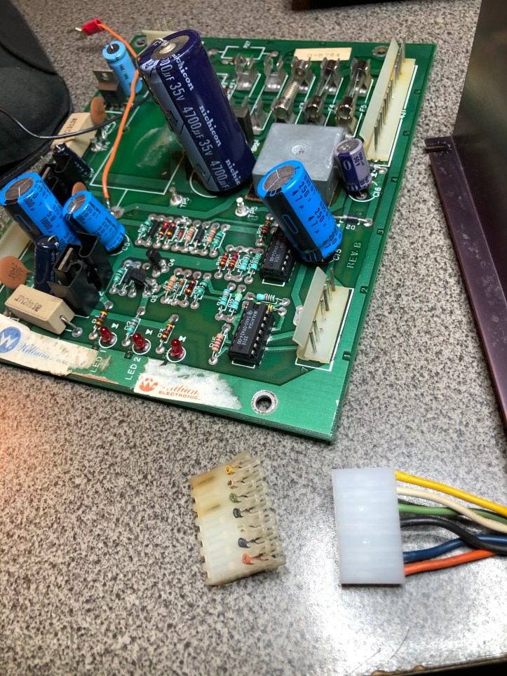
Gave the board a bath and replaced this IDC connector – I suppose the nice part is having it for a color reference. It will also be my pin holder when I reflow all the board connectors.
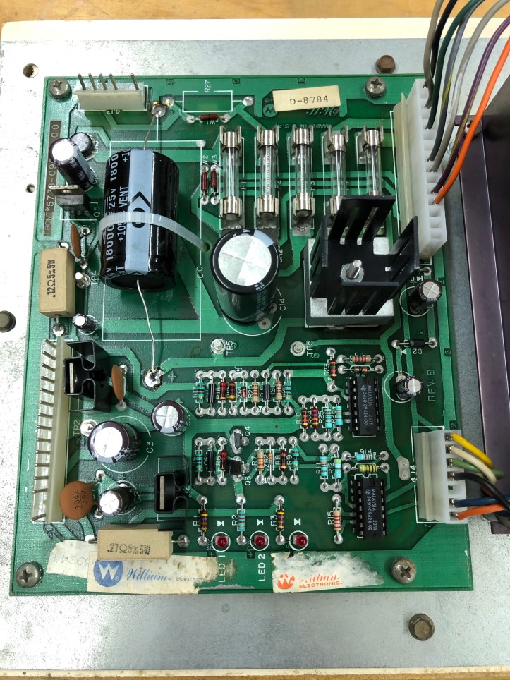
I tested the old caps coming out – they were all good – but what a mess. New set installed and I added a heat sink to the bridge rectifier I upgraded. At some point the original burned up and I couldn’t tell if the replacement was correct (it’s in a spares pile now)
I also found this on the outside of the coinbox:
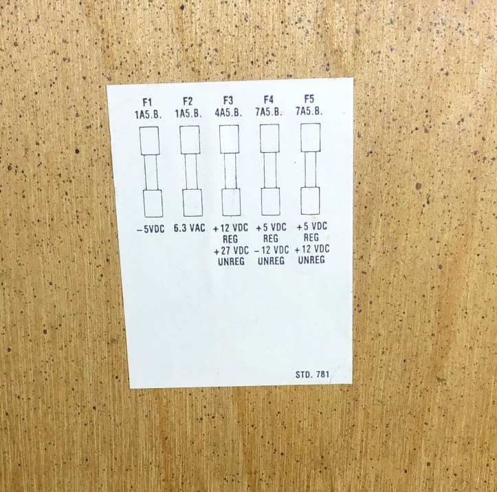
The cocktail fuses are labeled differently than the upright – turns out they are the same.
F2 on the upright is 5A SB, F2 on the cocktail is labeled 1A SB. Turns out this very official looking sticker is incorrect. You need to use a 5A SB fuse. The circuit with all the bulbs and resistor in place shows 2.1 Ohms resistance. 9.6v / 2.1 Ohms = 4.57 amps. The 1A fuse blew. I went back and did the math to determine the sticker is incorrect. I’ve updated my custom schematic and documentation to reflect the changes.
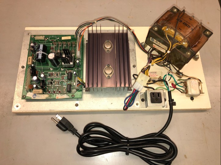
Bye bye switcher. Here it is with a new power cord. Fully bench tested and ready for the cabinet.. It did have the original power cord – but it wasn’t in very good shape. Not sure if they make reproduction Williams power cords. But these have been working just fine..

[…] Joust Cocktail – Power Supply Rehab […]
[…] Joust Cocktail – Power Supply Rehab […]