
I never really expected to work on a Major Havoc set. But I’ve been pretty lucky with this sort of thing. A good friend always wanted one – but an original is pretty hard to come by. He decided to get the reproduction cabinet and build the reproduction Major Havoc PCB. It’s been a long time in the making but there was a hiccup on the PCB.
Board#1 – Friends repro board
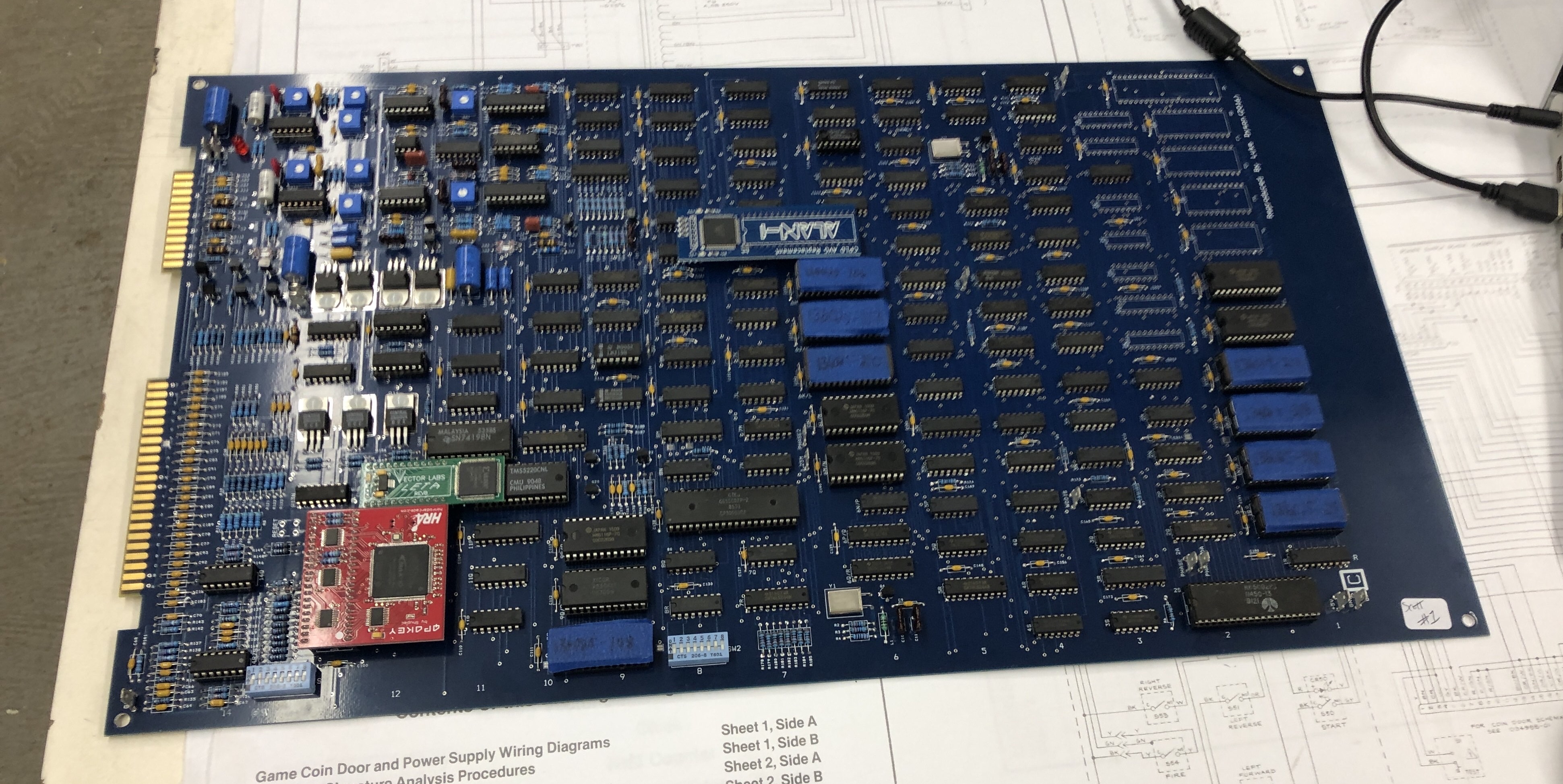
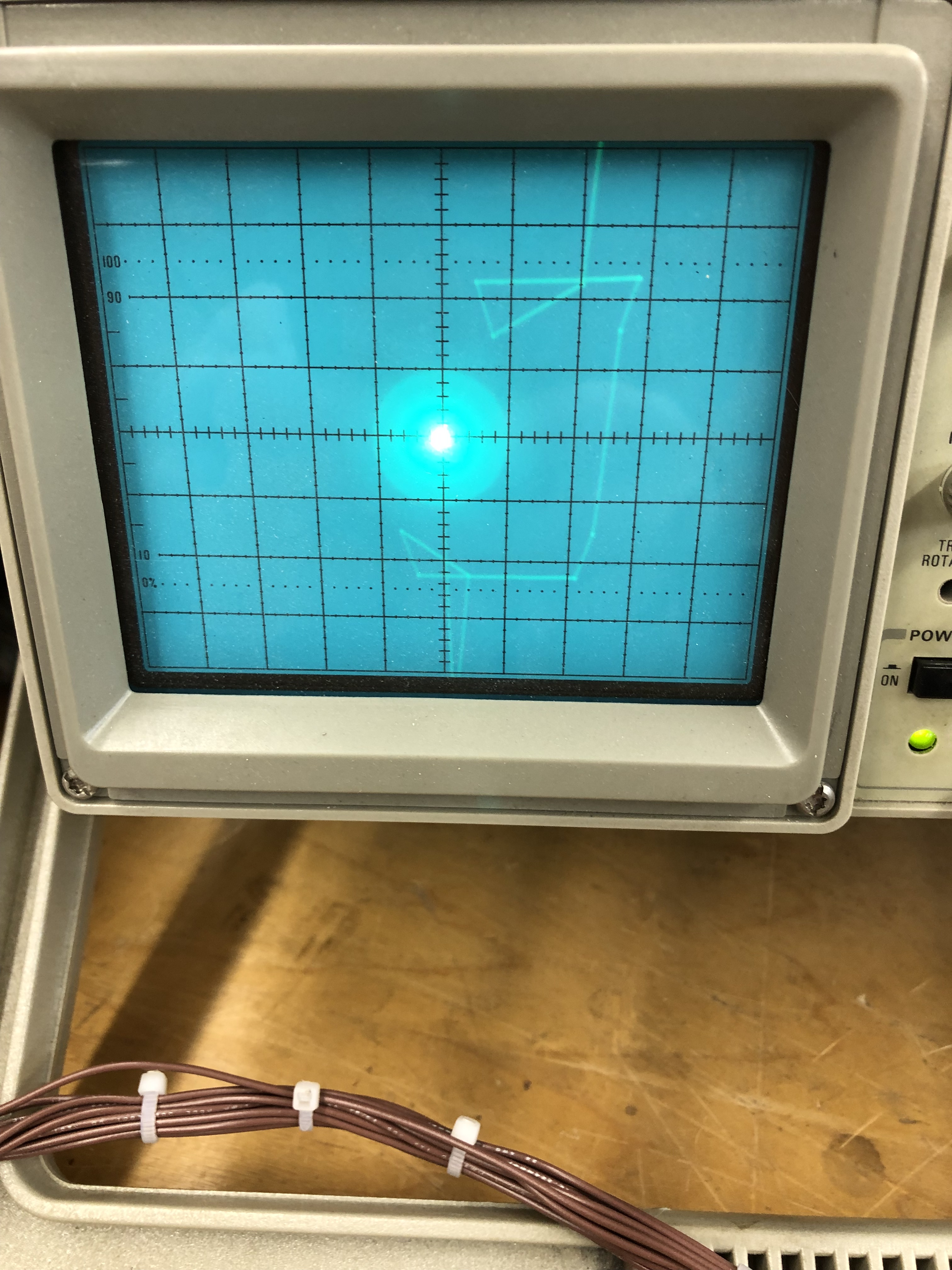
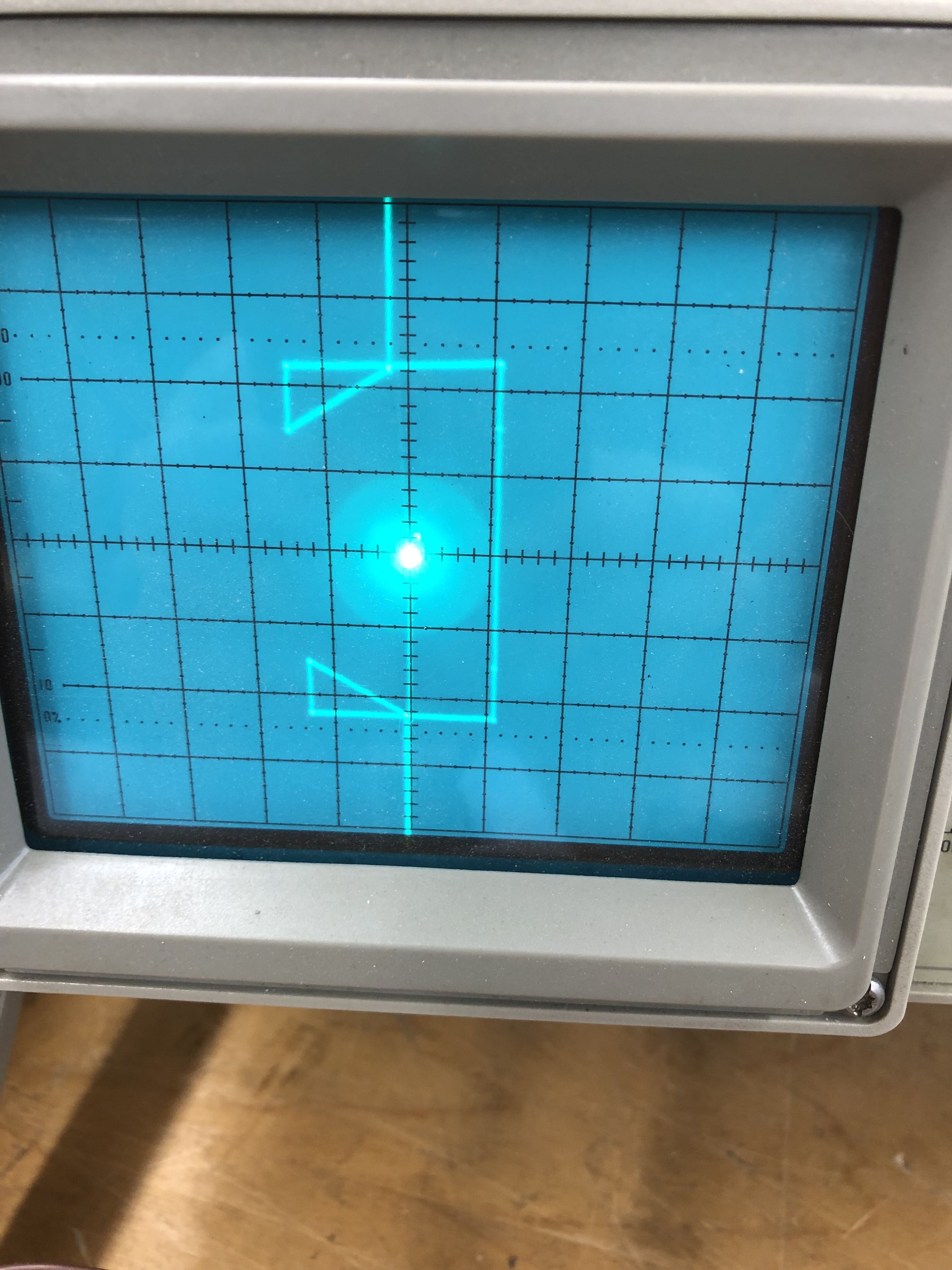
My buddy on the west coast did a really nice job collecting all the parts and assembling this board. Once all the bits and rare components were finally installed – we slowly brought it up on a bench supply and made sure it wasn’t pulling too much current. Poked around with a logic probe and it seemed to be running (no resets on the CPU’s). Next he connected to the repro harness and connected the X/Y to a scope and the game was running.
When we connected it to a monitor…
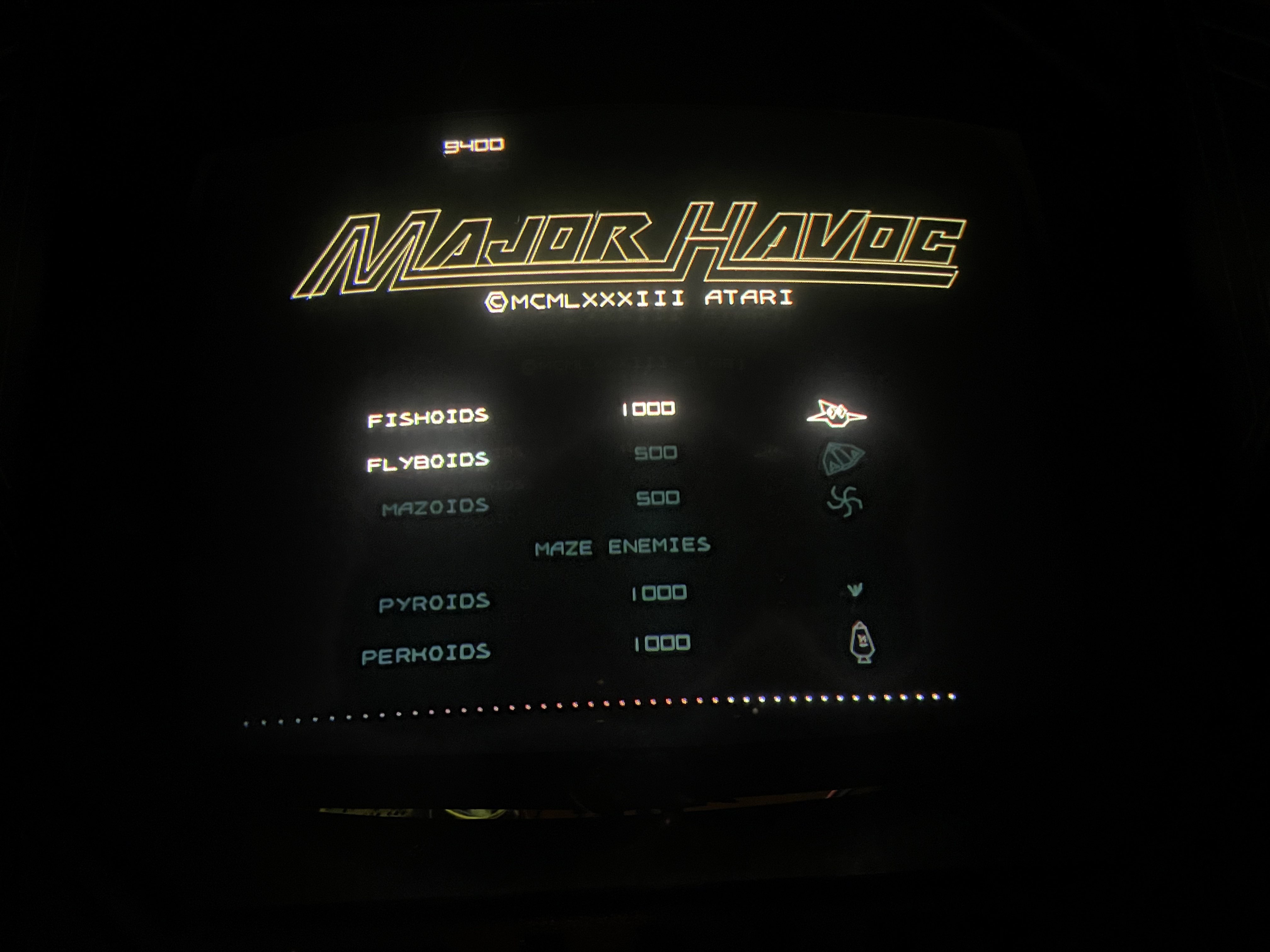
Pretty much everything came out all white. Because the entire cab was being assembled from untested/new components – it took a while to determine the monitor was good, power was good, etc.. Once we got to the PCB, we determined that all 3 colors were locked on vs. toggling as they should. After a number of coast to coast debugging sessions.. the board found it’s way to me.

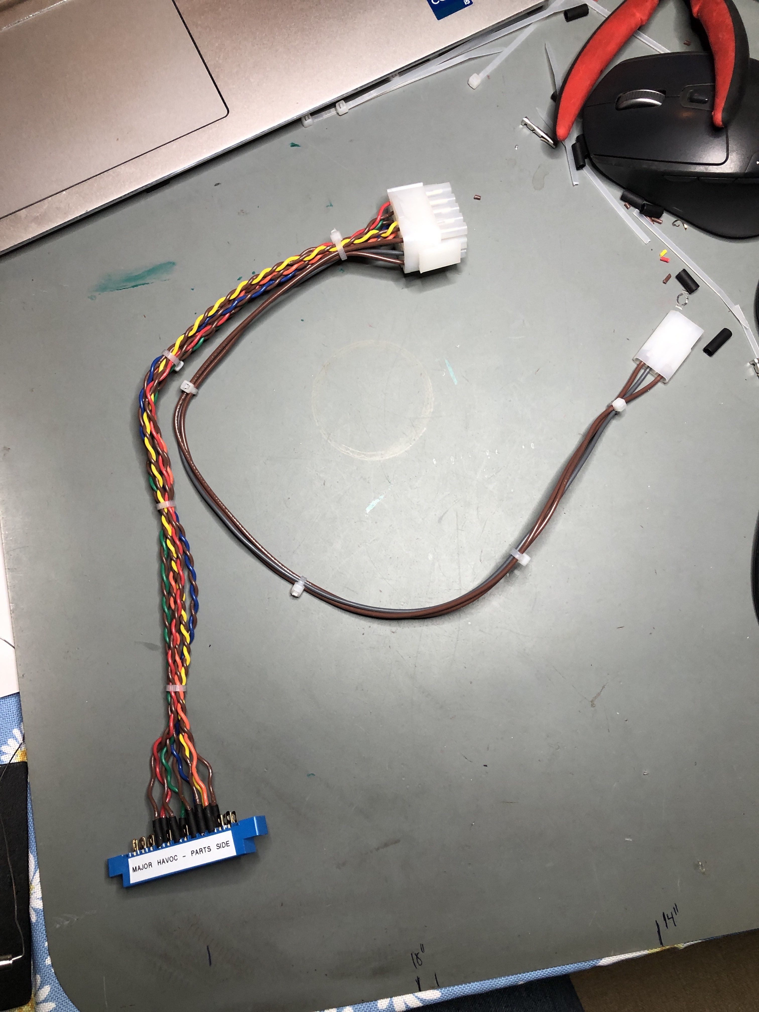
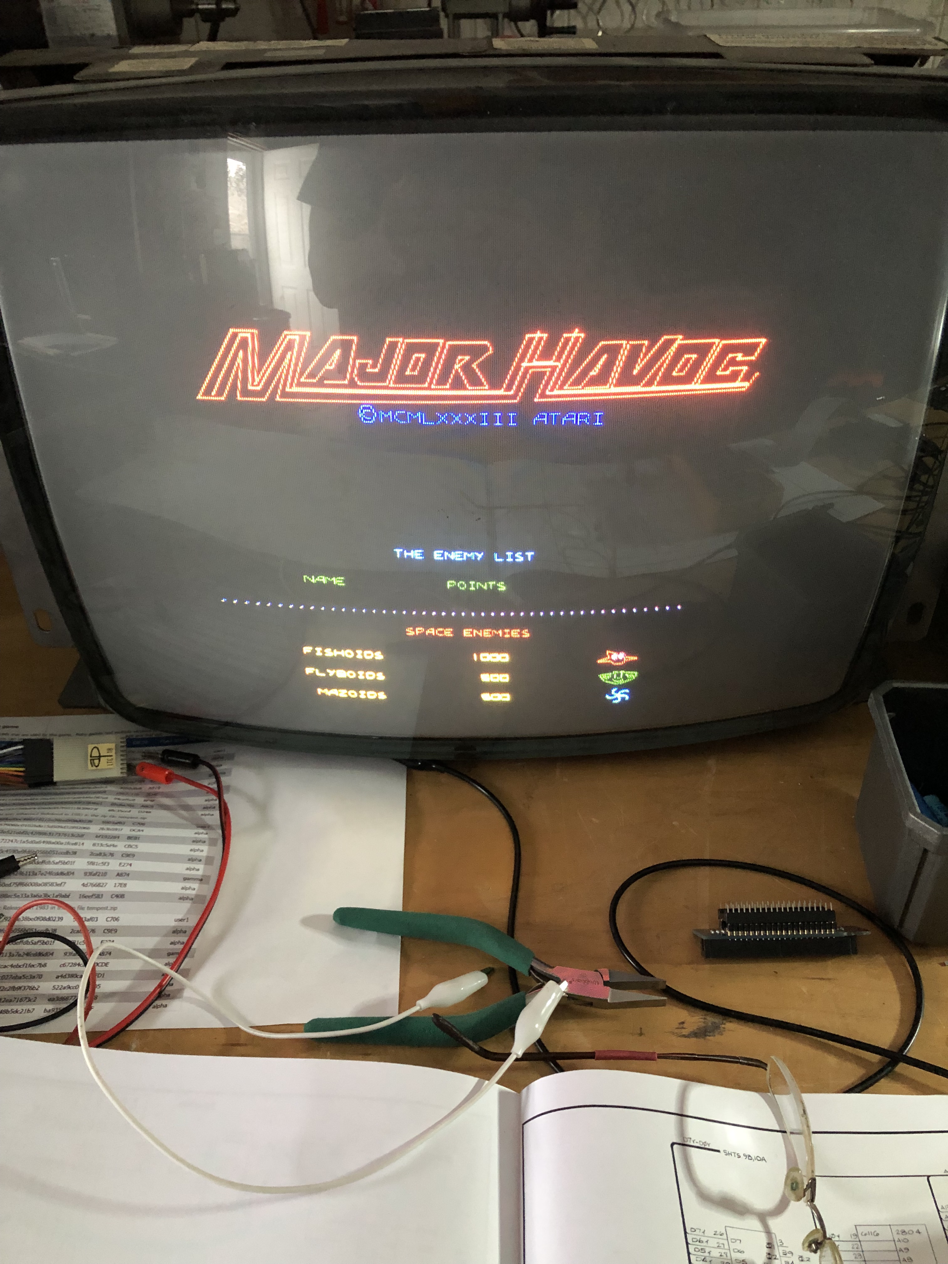
Built a Major Havoc adapter for my test rig. It’s a great weekend morning with coffee activity.

Once I got the board on the bench – it didn’t take too long to determine that the RAM@12J, 12K was the issue. They were getting data in but just outputting 1’s. Most likely counterfeit unfortunately. Popped a couple good ones in and we had full color. Debugging coast to coast got us really close. But double failures are tricky to locate.
Board works!
Board #2 – in for repair
Lucky me – had a fully working and testing rig and I got a referral. This board had been out for 8 months with someone else and it got returned that they could not repair it. My kind of project. I’ve fixed many many unfixable boards at this point.
Sent in with reported graphics issues – but wait – there’s more…
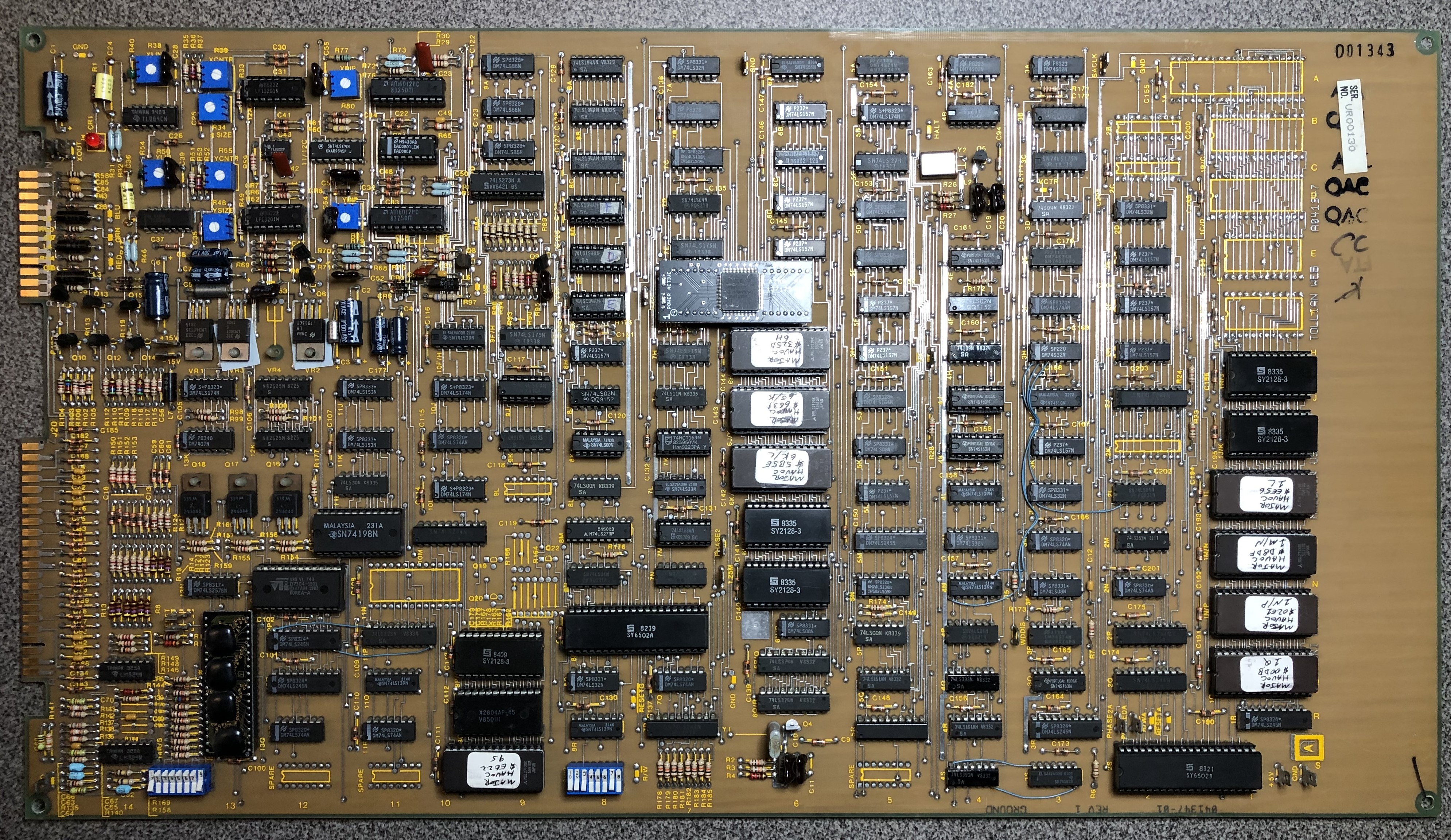
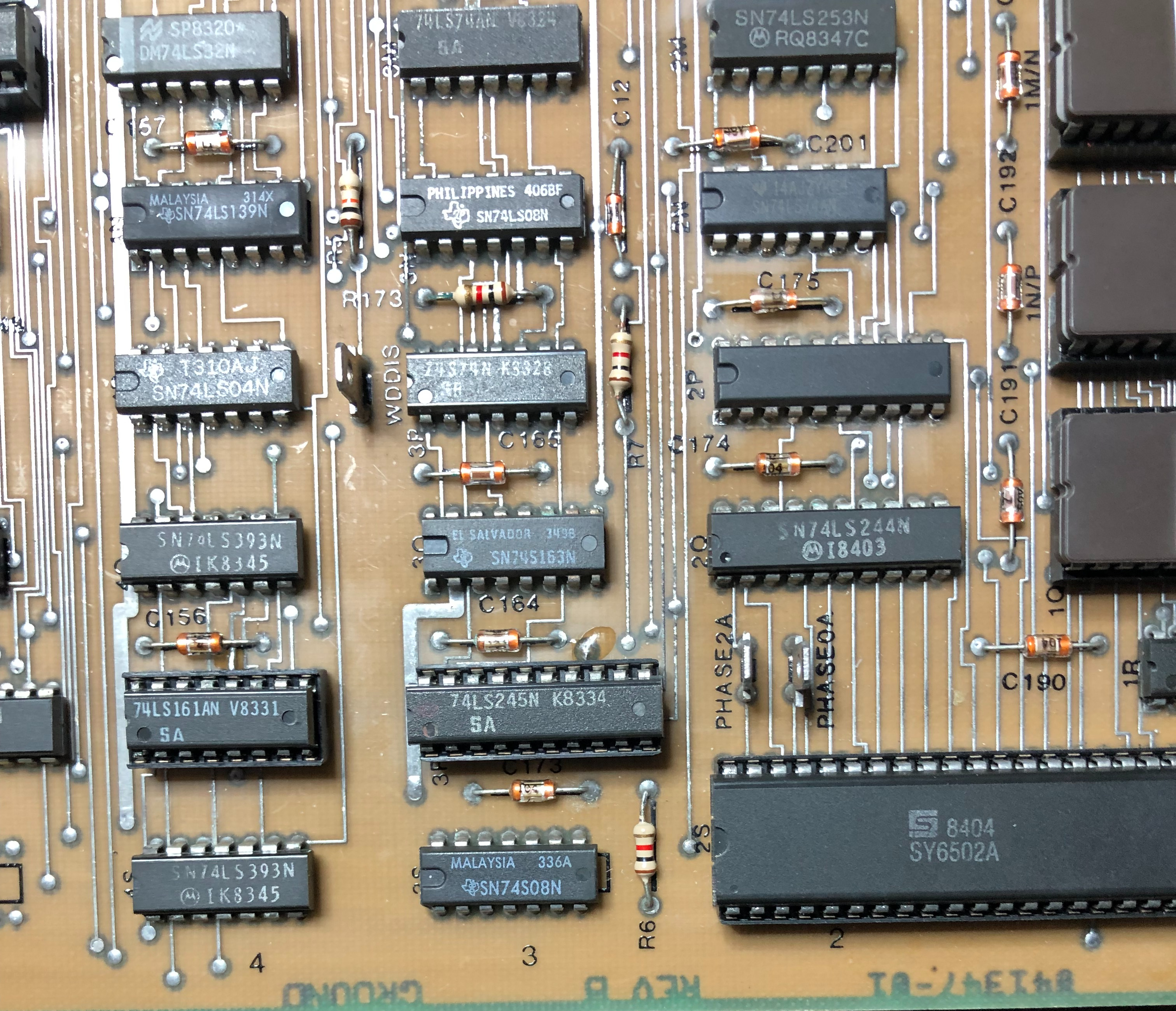
Nice original board – there is a fair amount of prior work – but overall this one is pretty clean in terms of the prior work done. Nothing messed up and no hackery. Look at that original quad Pokey.. (chip with what looks like 4 gumdrops on top).
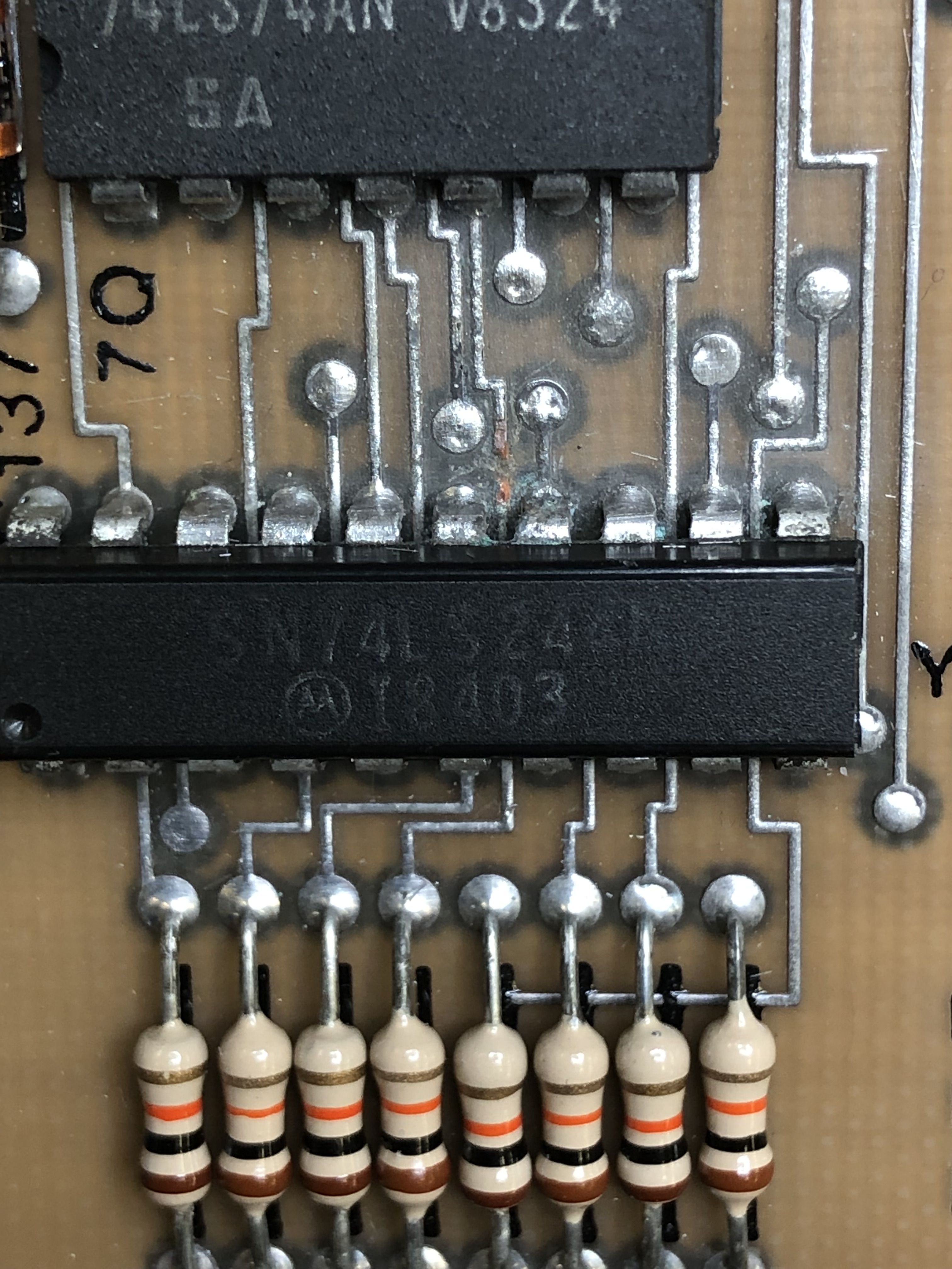
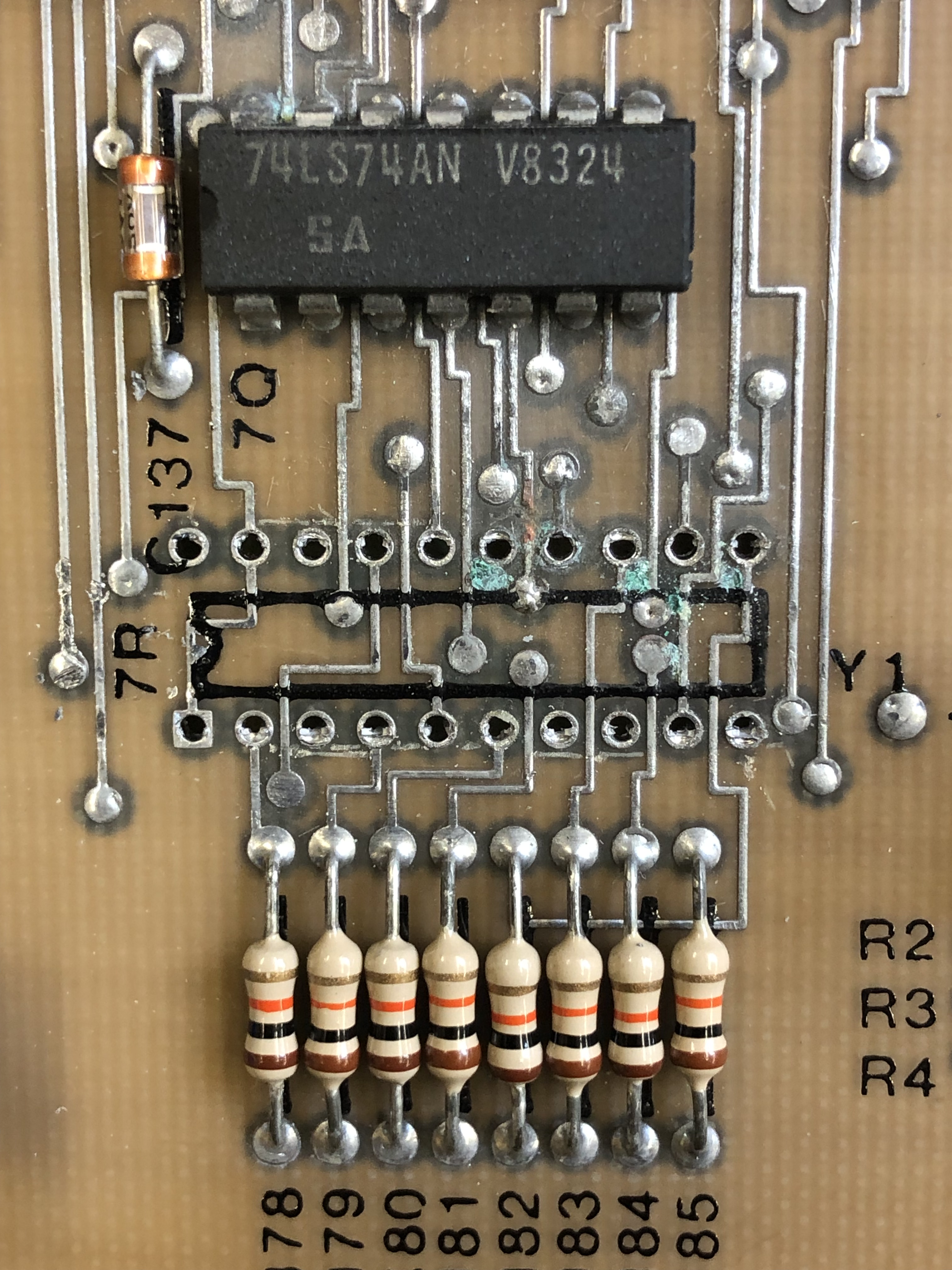
After checking RAM, ROM and the vector generator – all seemed to be in pretty good shape. Last in the chain are the data shifters that feed the DACs (amongst other things)
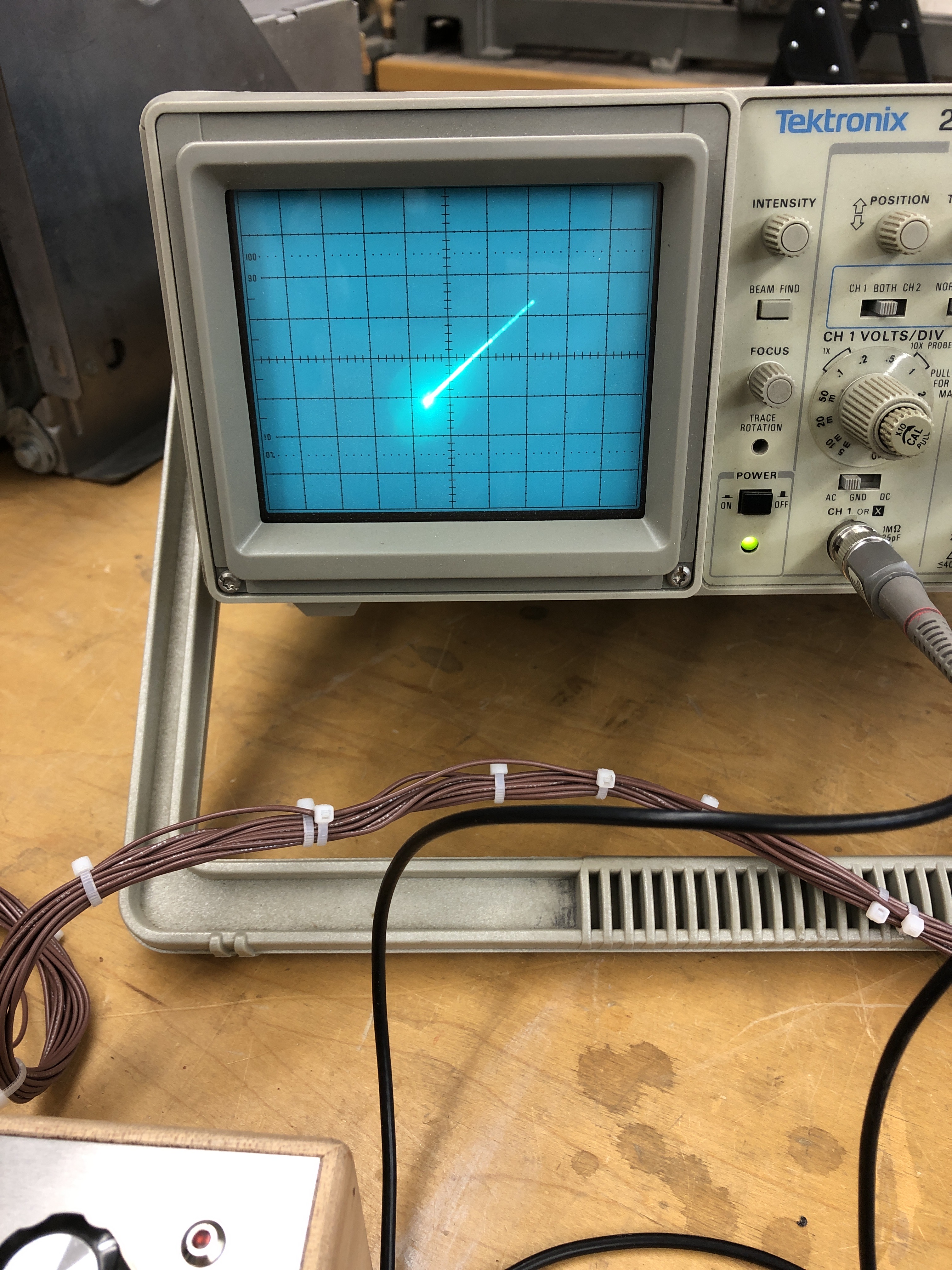
Putting a test pattern into the machine – on the left – Bad 74LS194@8A – replaced on the right. Good information now getting to the DACs.
The next item took a bunch of hours to track down.. Intermittent board issues can be miserable to find. Video would completely go blank just by flexing/touching the board just the slightest bit – anywhere from about the center of the PCB to the edge connector.. It was sensitive just about everywhere and trying to find the epicenter was not really going well. Trying to trace the issues from the XY outputs backwards was problematic too. In hindsight there were likely faster ways to find this problem – but it was tricky to locate.
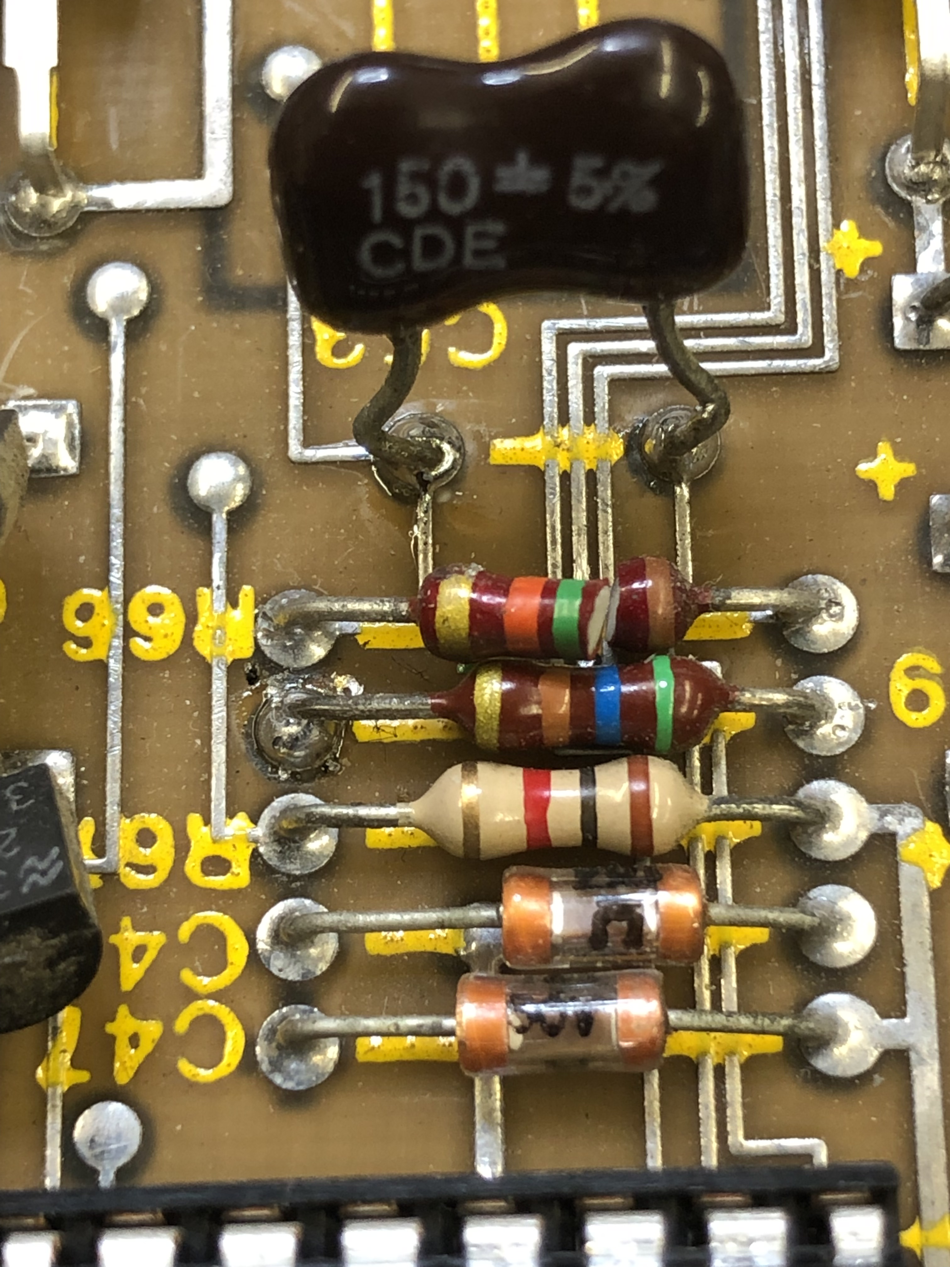
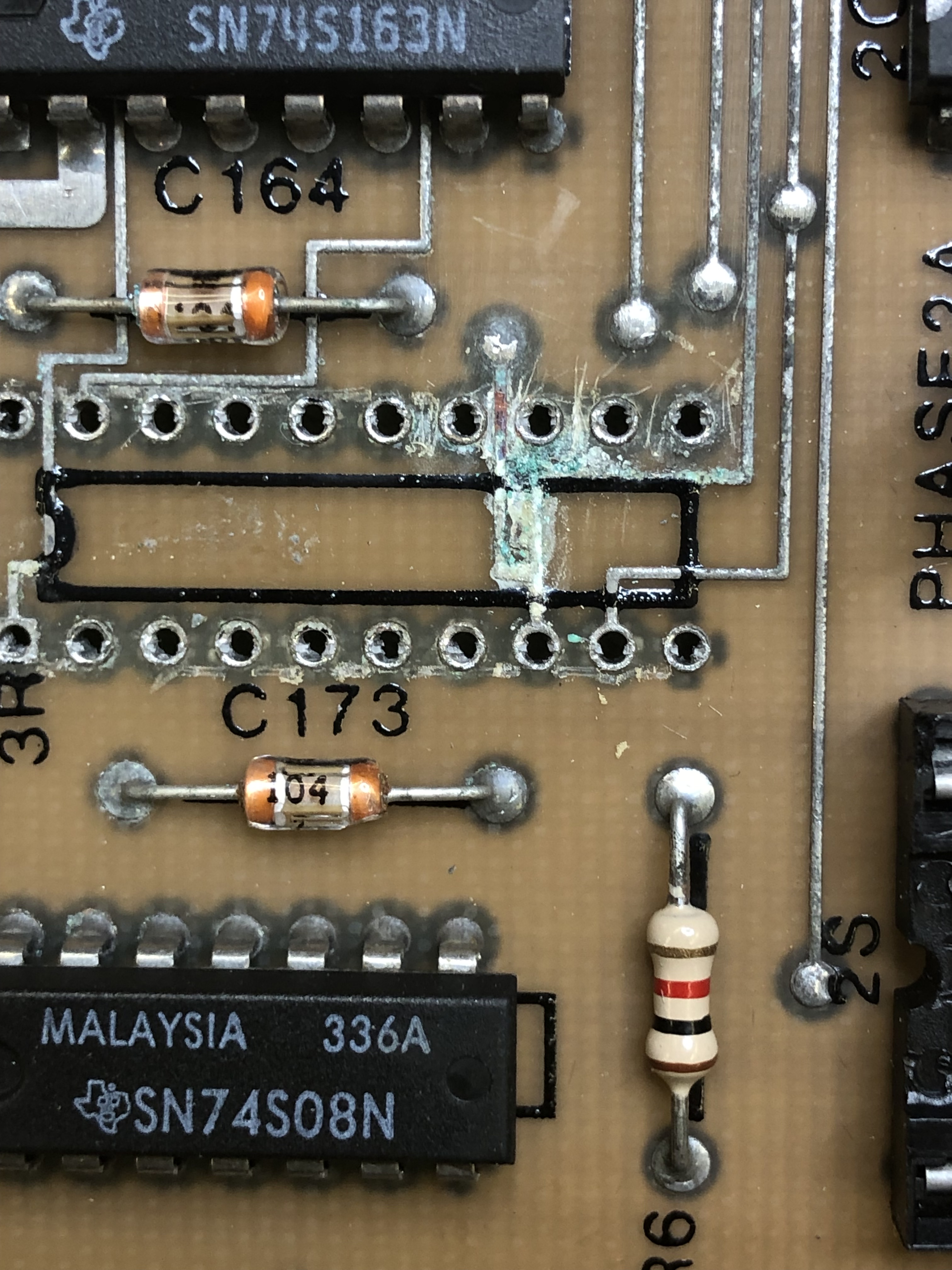
Pressing down on this area where these resistors are what caused the video output on the right. R66 was the root cause. It was not broken visibly when I was debugging. Flexing the board and checking on the scope got me to the point where it almost seemed there was a short or something going on under these. I poked at this resistor with a chip lifting tool to try and flex it up just a hair and it broke very very easily. Could it be that simple? Yes! There must have been a microfracture in that resistor which caused all of the video cutting out issues.
When that was repaired – the color RED would cut in and out.
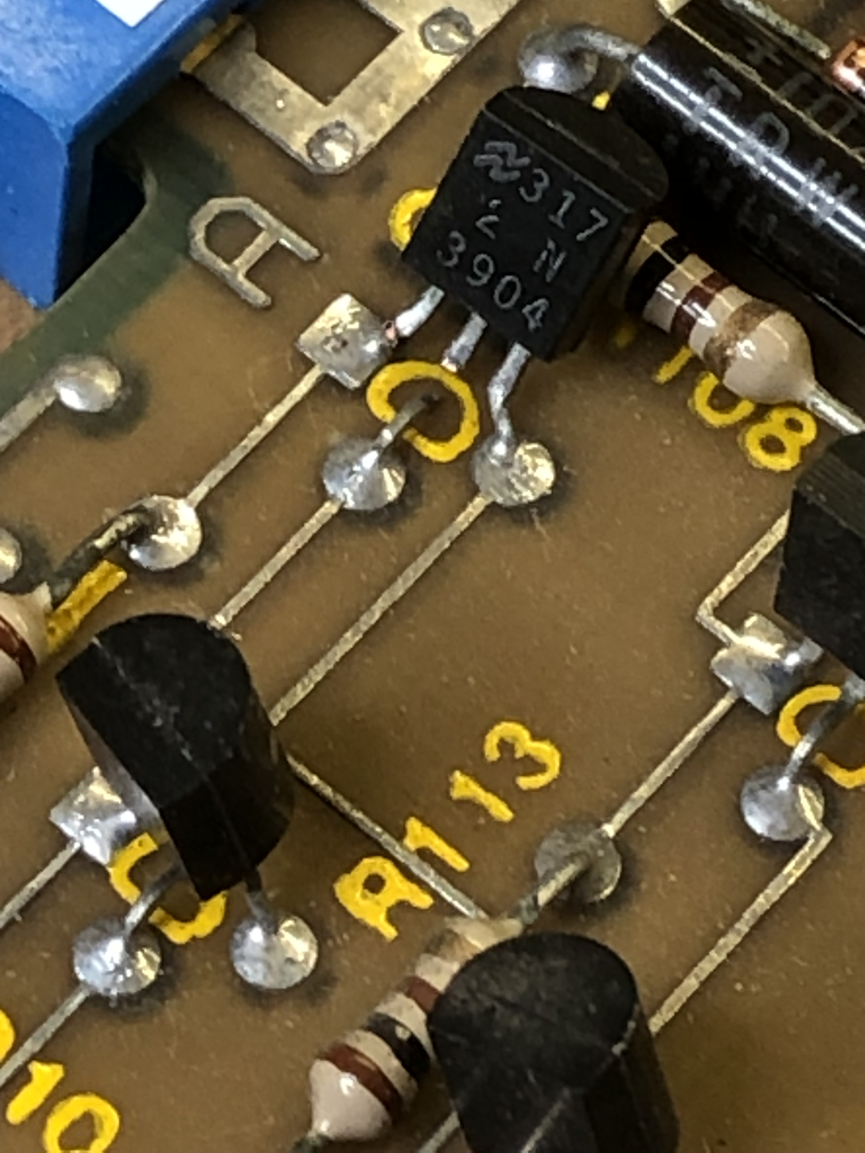
This transistor right by the edge connector had been hit too many times. Easy fix.
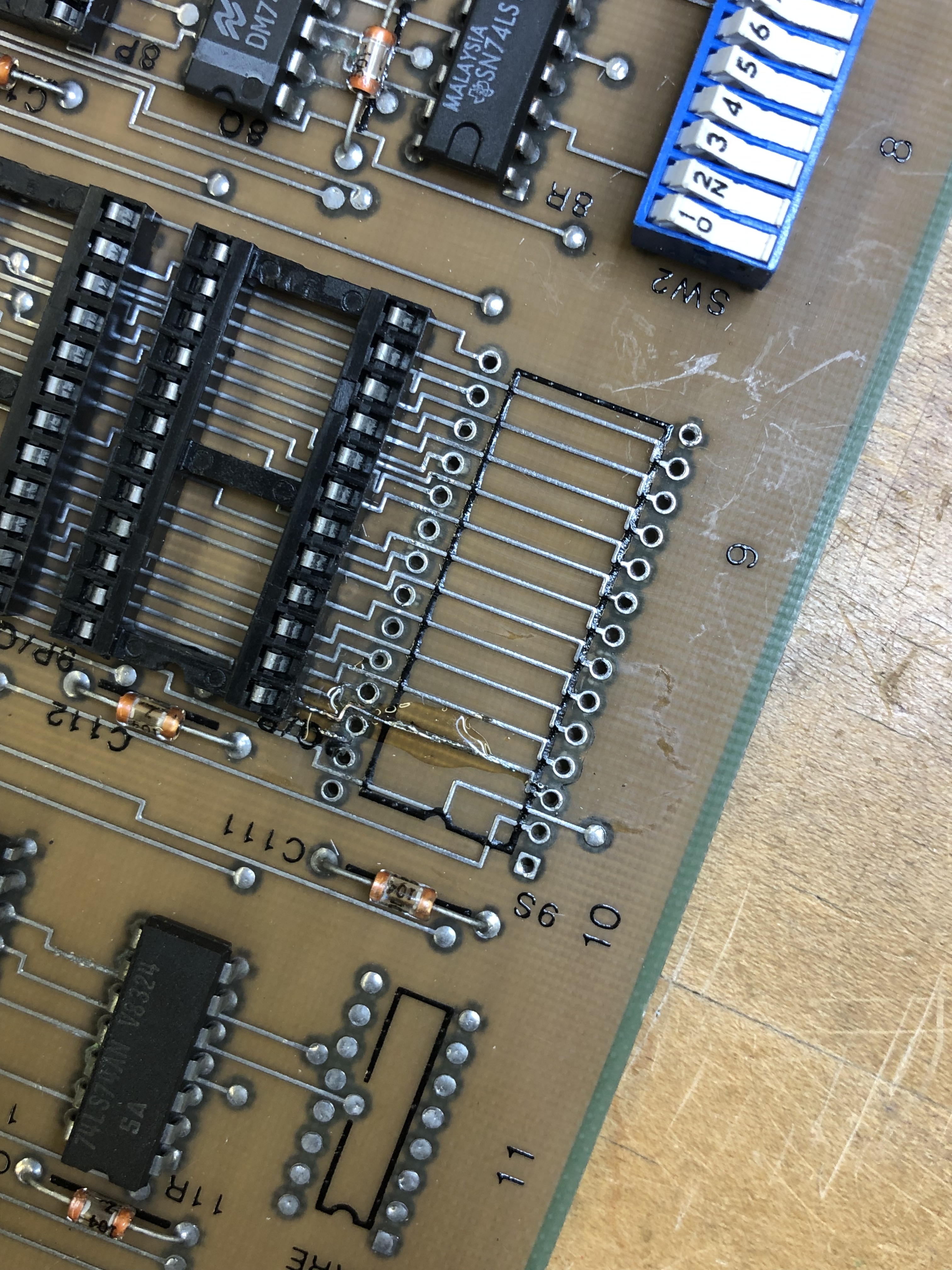
The last item was that dip switch bank1 (SW1) was not working correctly.

My big concern was SW1 was direct connected to the Quad Pokey and that maybe the Pokey was dead on these connections – that would be horrible – and expensive to replace. The alternative was to have those game settings be fixed in the ON positions.
Upon further inspection:

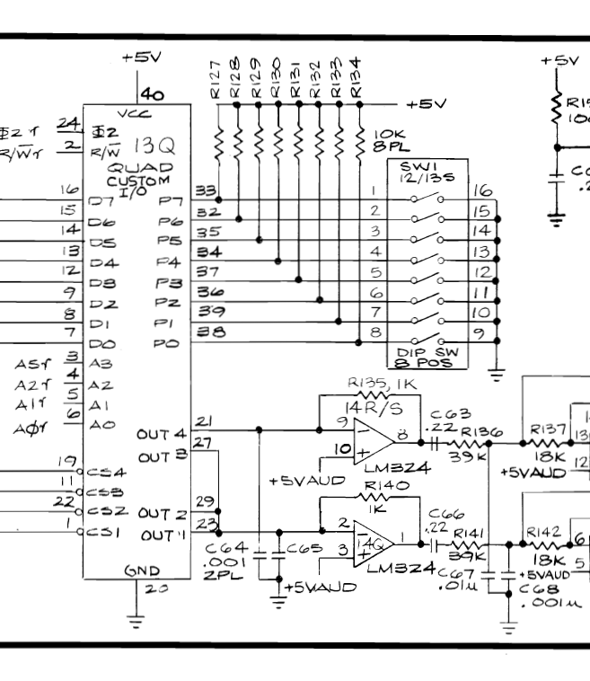
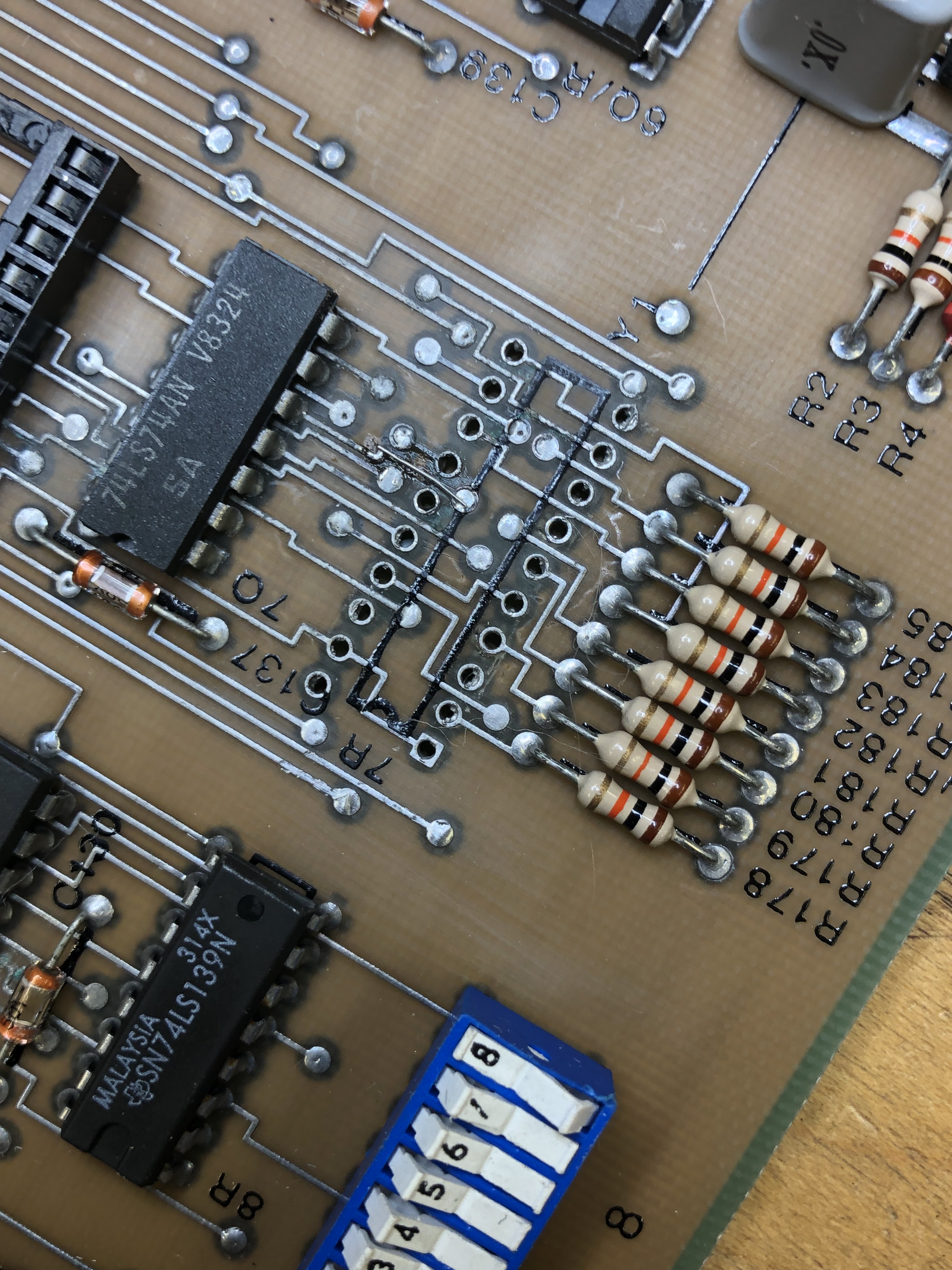
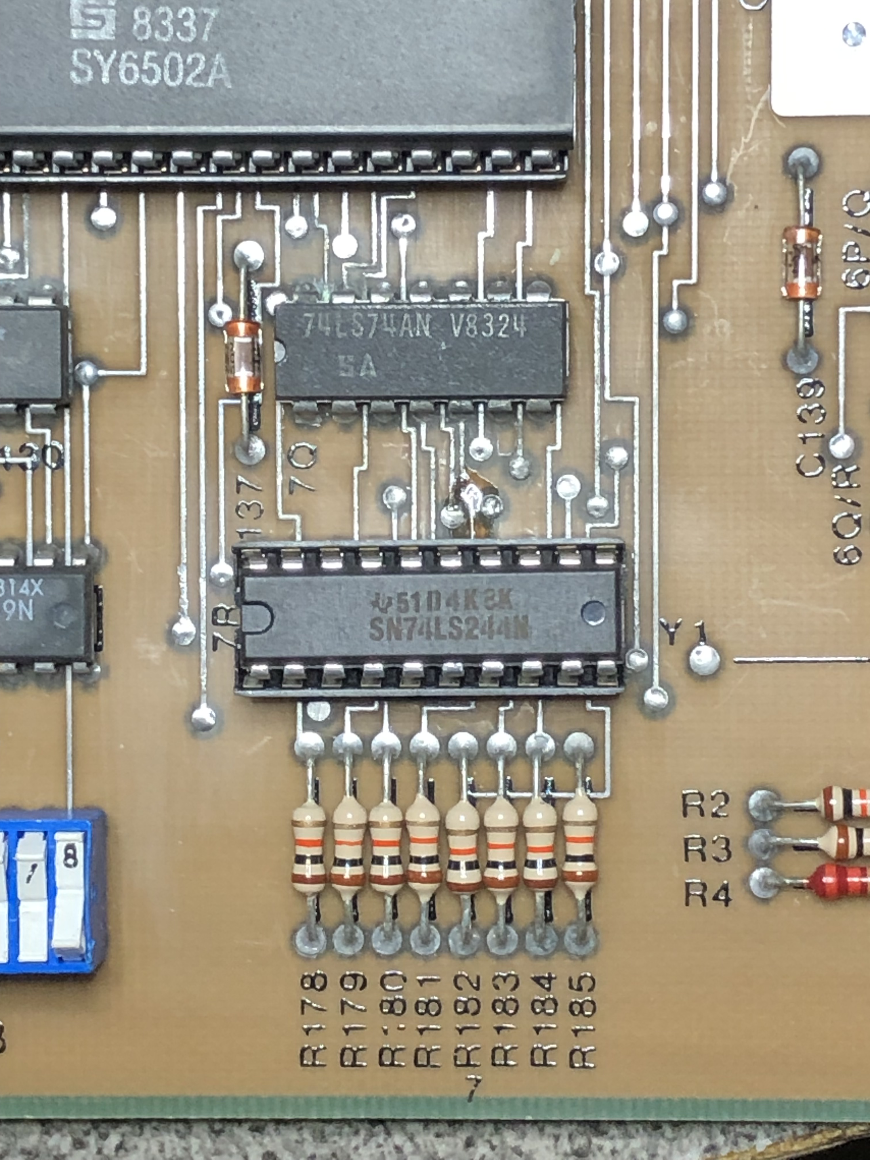
At some point in time – all but 2 of the resistors for SW1 had been purposely snipped. Why??
Replaced all of the cut resistors.

Ran this board for 4 x 12 hour days – rock solid.
Board works!!
Looking forward to working on more of these in the future.
Board #3 – Board in for repair – keep them coming!
Initial triage – both CPU’s not running
Board received without a quad Pokey – can’t test sound and game runs oddly because the Pokeys are in front of the DIP switches, which set the game options.

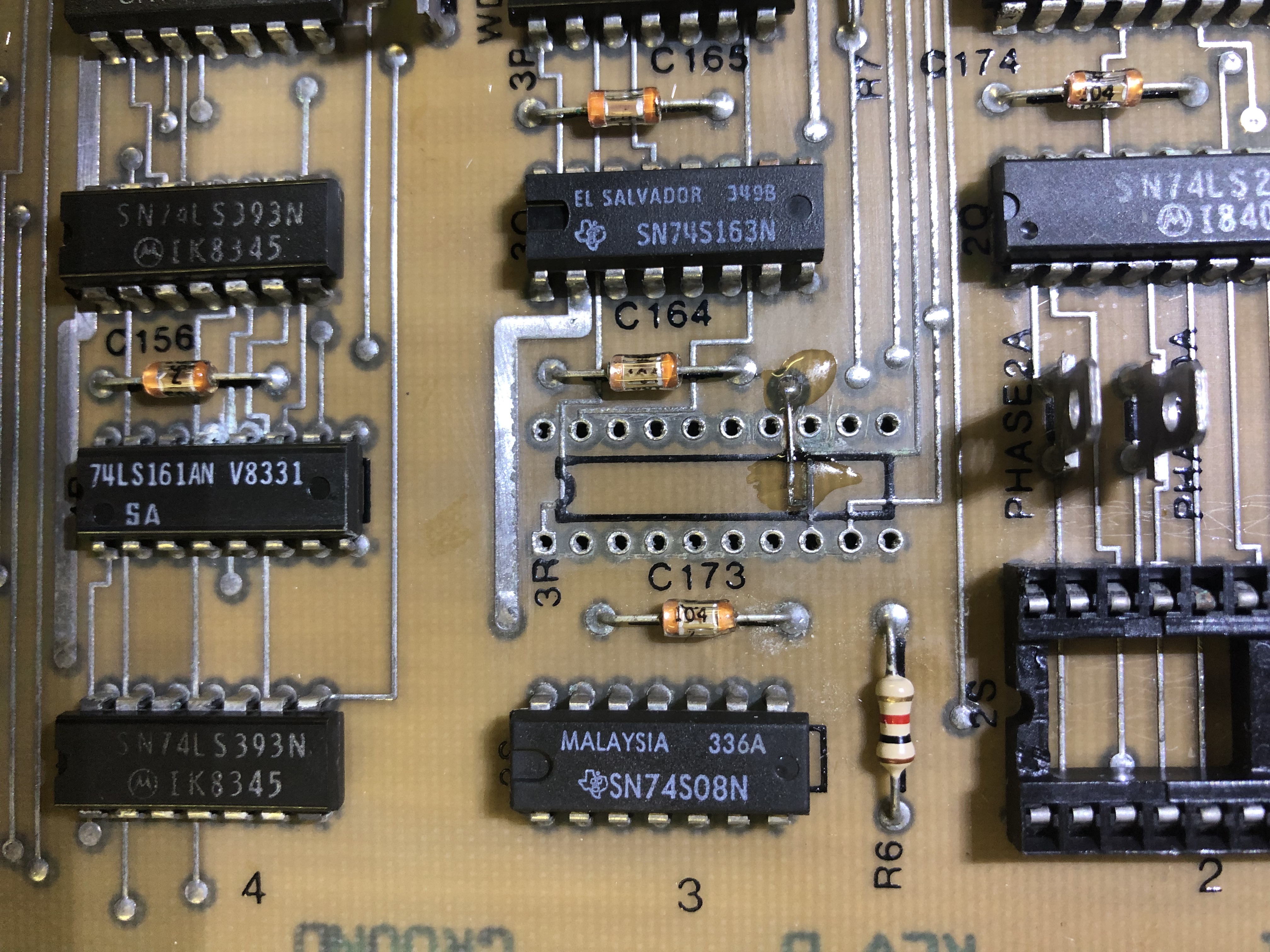
This board has a number of areas with corrosion, however it isn’t even across the entire board. It is scattered around. Not really sure how that can happen..
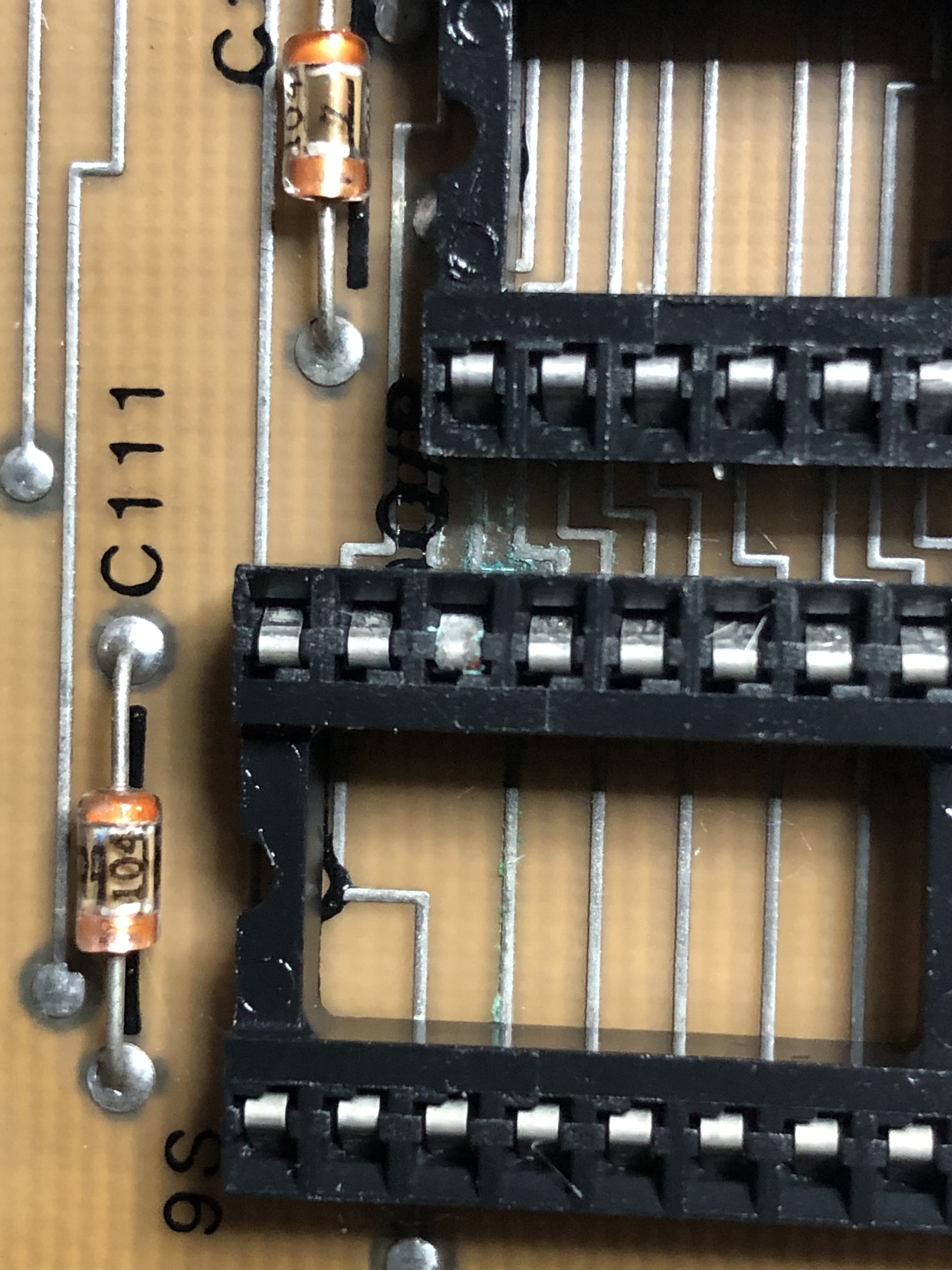
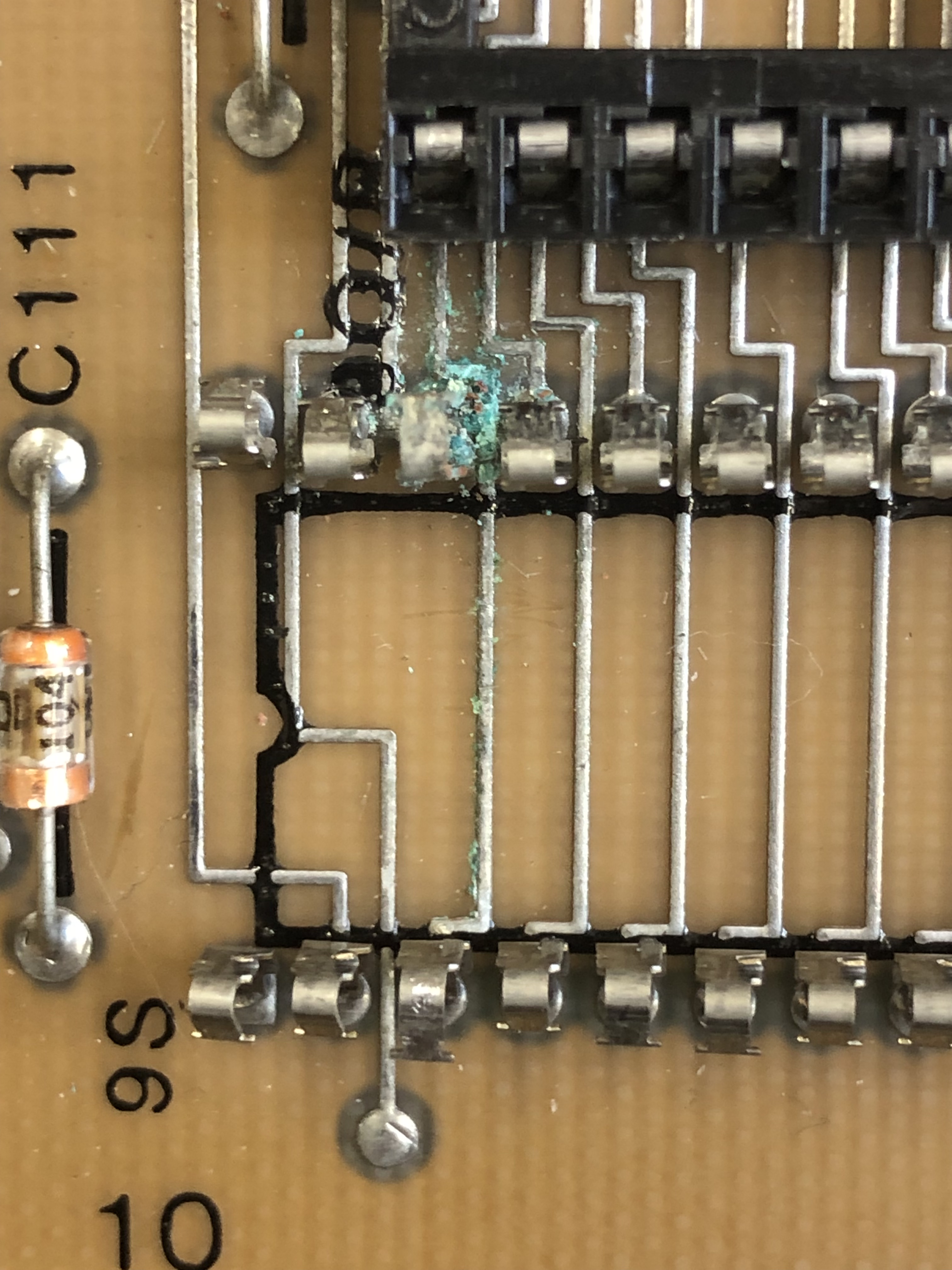
Here at 7R you can see a break – but there was plenty of corrosion below the chip

Here the corrosion has been removed, a Kynar wire connected and then I lock it in with a clear UV cured material that holds it in place and prevents the joint from breaking when applying heat while soldering.
Barely visible repair and indestructible now.
Bad pins and corrosion everywhere. Each had to be corrected individually to make clean connections. After a number of hours of finding these and correcting a missing clock due to a bad crystal.

Board works!!
Board#4 – Friends repro board #2

Buddy sent me his second repro board for MH. This one is going into a second repro cab that will get sold once completed. Somewhere along the way, he had a “power event” and it stopped working.
Took a little time with it, but all 5 RAM, the AVG chip and the 6502B were all bad. Seems odd that only those chips had issues. I’m not convinced the RAM was going to work correctly. The initial reason for messing with it (it did work) is the text is jittery. Through some research, we found that changing R68 from 10K to 23K greatly reduces the jitter. There remains just a bit of X-axis jitter on some of the lettering
There are also VDRs – voltage dependent resistors that we believe are not working correctly – A set of repro chips will be tested to see if it clears that up.
Board works!
Board#5 – my personal board
Since adding Major Havoc to my repair list, I’d been looking for an original board that could go in my Tempest cabinet – and – that I could use for reference. I picked one up a while back and it worked correctly. Until I started working on Board #4..
My board stopped working during testing. I chased what looked like a bad signal on address line #4 on the gamma CPU for a little, turned out to be a bad socket. After that the board still would not boot. It was stuck in a watchdog and the gamma CPU was never coming out of reset so it could boot. I suspected 74LS273@8M was the cause:
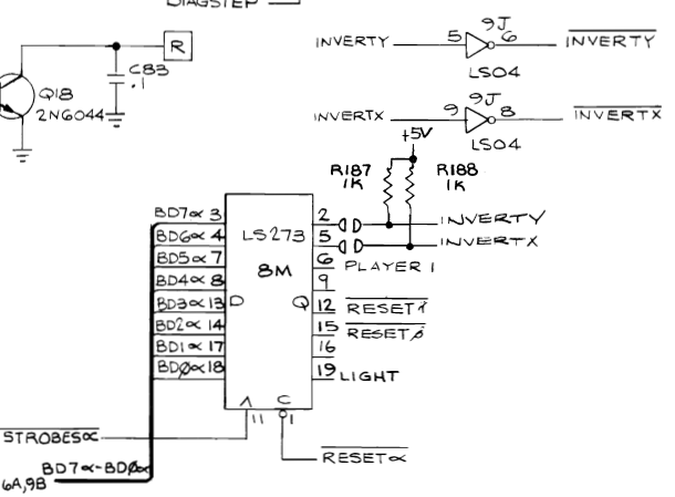
It seemed RESET (gamma) was not allowed to go high on PIN12. As a test, I used a probe and pulled it high with 5v+. Game sprang to life and I smelled a little burned up chip. Replaced the LS273@8M.
Board works!

Can you point me to a comprehensive BOM for the Major Havoc PCB? My Google-fu is not up to the job, apparently. Thanks!
https://forums.arcade-museum.com/threads/major-havoc-pcb-blank-pre-order.394654/page-19#post-4413358
This thread has the best info on a full parts list.