
I was asked if I could work on a couple of Warlords PCBs.. I said sure!!
First step is to build a new adapter for my Bench Power Test Rig.
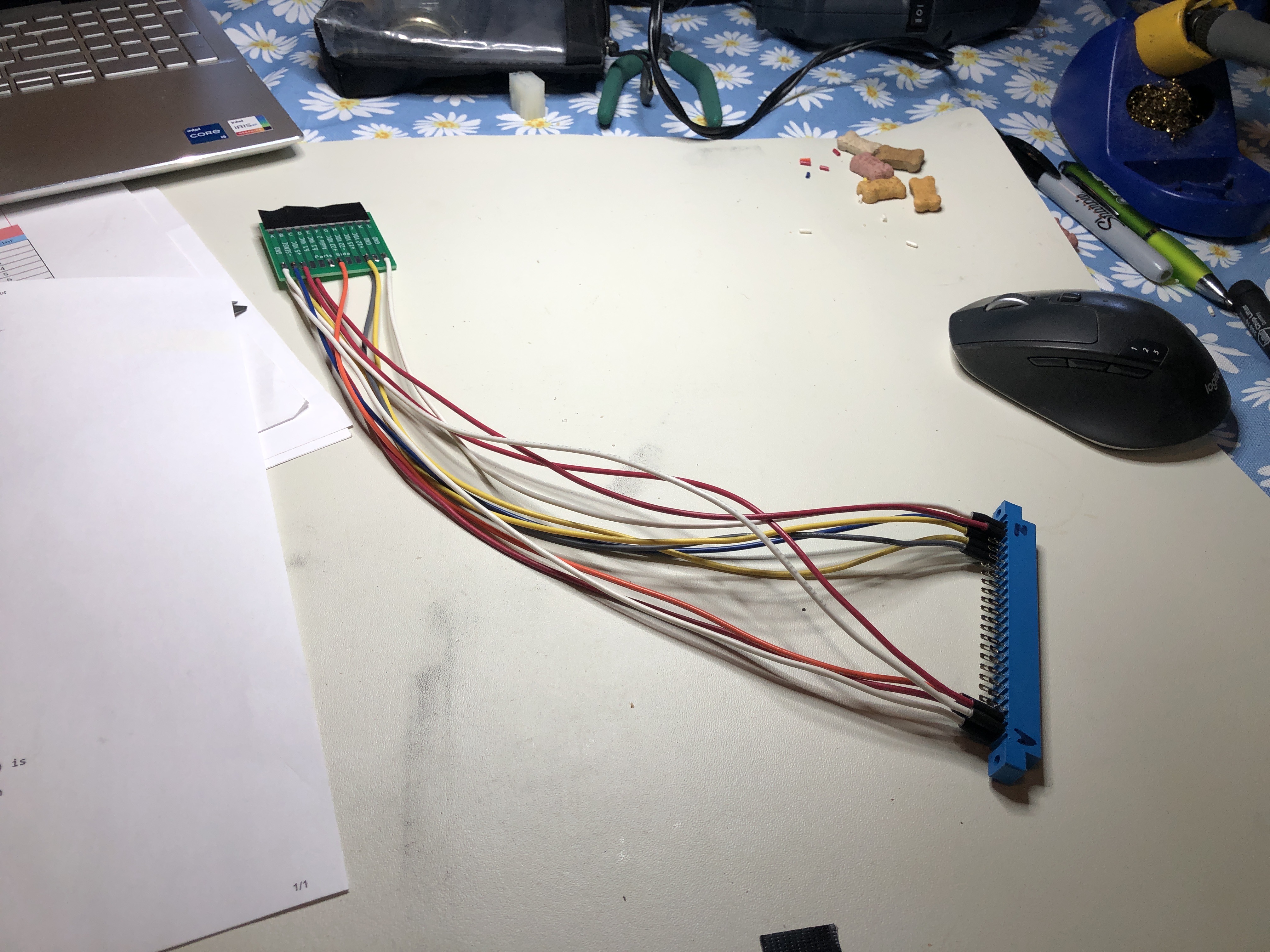


I start with 18G wire for all the power connections, then use 22G wire for all the remaining ones. Power first, video second and controls last. The end result is an adapter that I know tests the board using all of the factory voltages, etc. Some Jamma adapters bypass some voltages in some cases, so I tend to avoid them. Switching between boards takes a few seconds as compared to bench supplies clipped to the PCB. It takes a couple hours to build and test the adapter, but the time gets saved not having clip to each board individually for repair and testing.
Board #1 – In for repair
Triage:
- Some prior work – many new sockets
- Graphics corrupted

Here is the game in upright mode after running through all of the standard board maintenance. I ran some memory tests and determined that the lower 4 bits of video memory at each location were always being read as 0x0F even if the the actual memory contents were 0x00, 0x01, etc.
I spent some time looking at the playfield multiplexer as this is where the issue seemed to be centered.
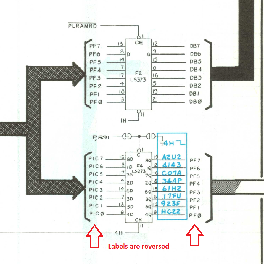

Found an error on the schematic – the labels on F4 are on the swapped. I ended up pulling all 3 of these chips as there was a phantom clock on PF0. This told me there was a short on the board. After hunting around for the same frequency for a while – I finally ran into it.

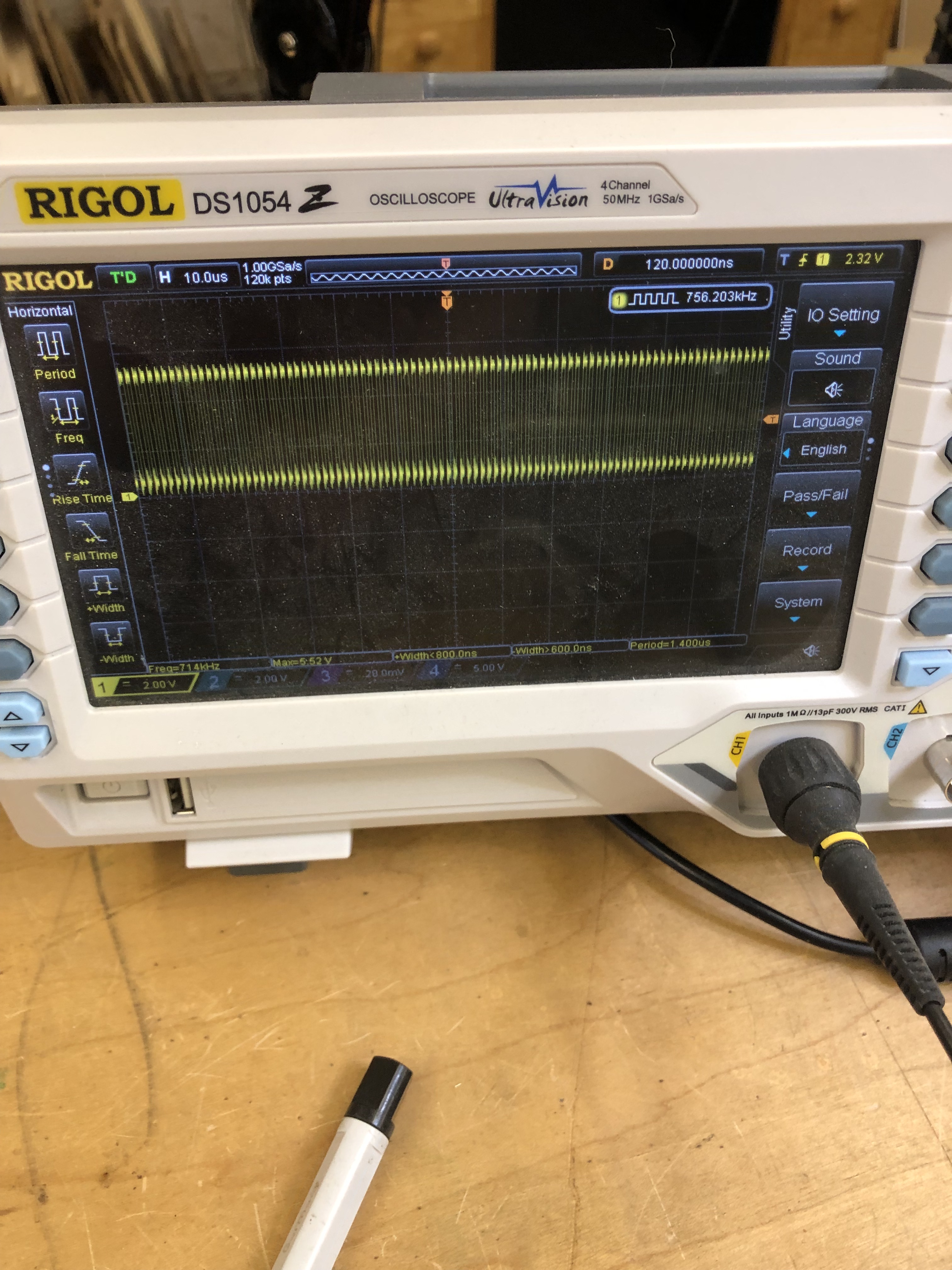
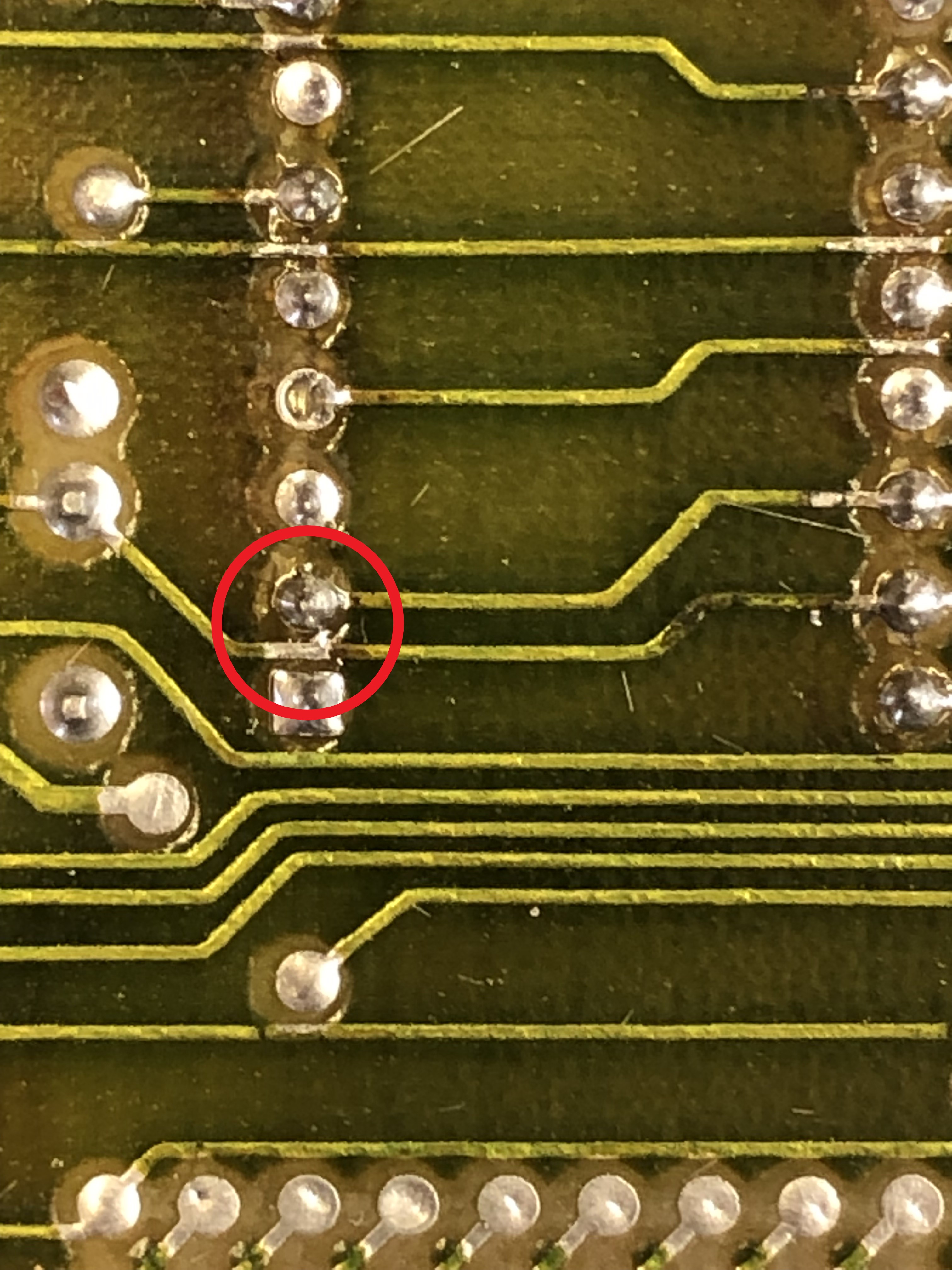
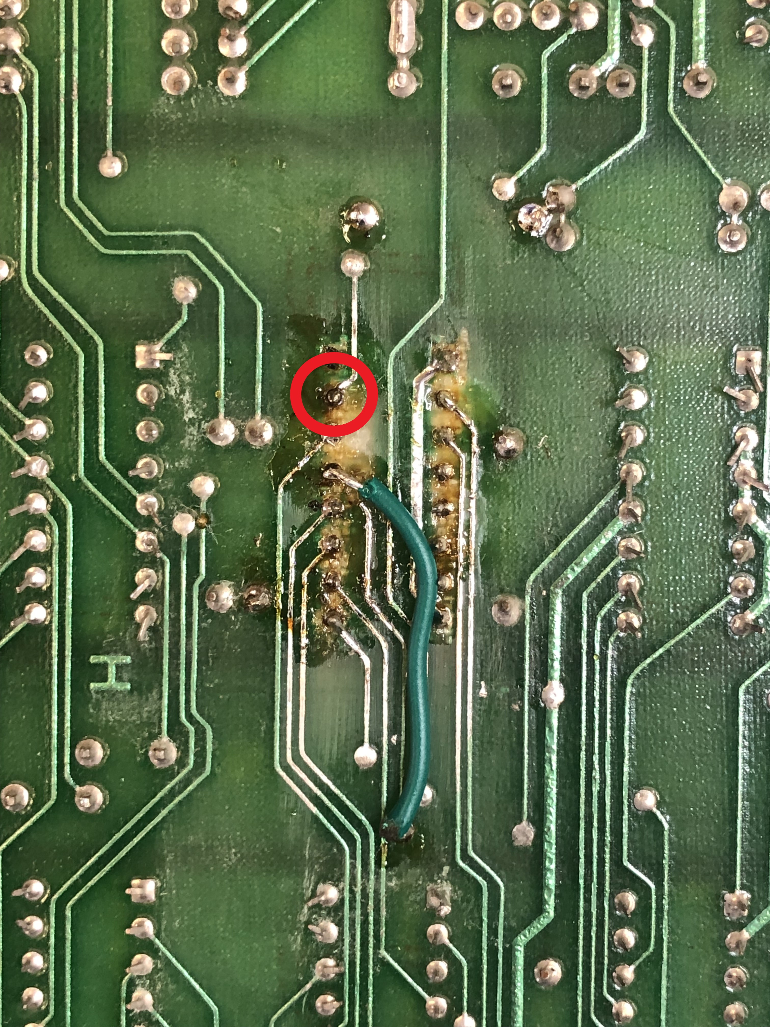
The bank of RAM L3, K3, J3, H3 are the the lower 4 bits of the video ram. Pin 17 is a chip enable that should have a clean 5v+ on it.. On the scope it has a clean 756.2 kHZ clock.. That’s not right! In the red circle is Pin 39 on the CPU.

Pin 39 is the clock signal that I had on the scope – it is shorted to Pin 2, which in also connected to 5v+ P,R90 and is sent around the board in a few places. I’m surprised as so much of the game ran.. In the end the only thing it seemed to effect is the RAM it was enabling on/off. I can’t confirm but I believe the LS153@H4 may have been bad.. I ended up replacing all 3 of those chips.
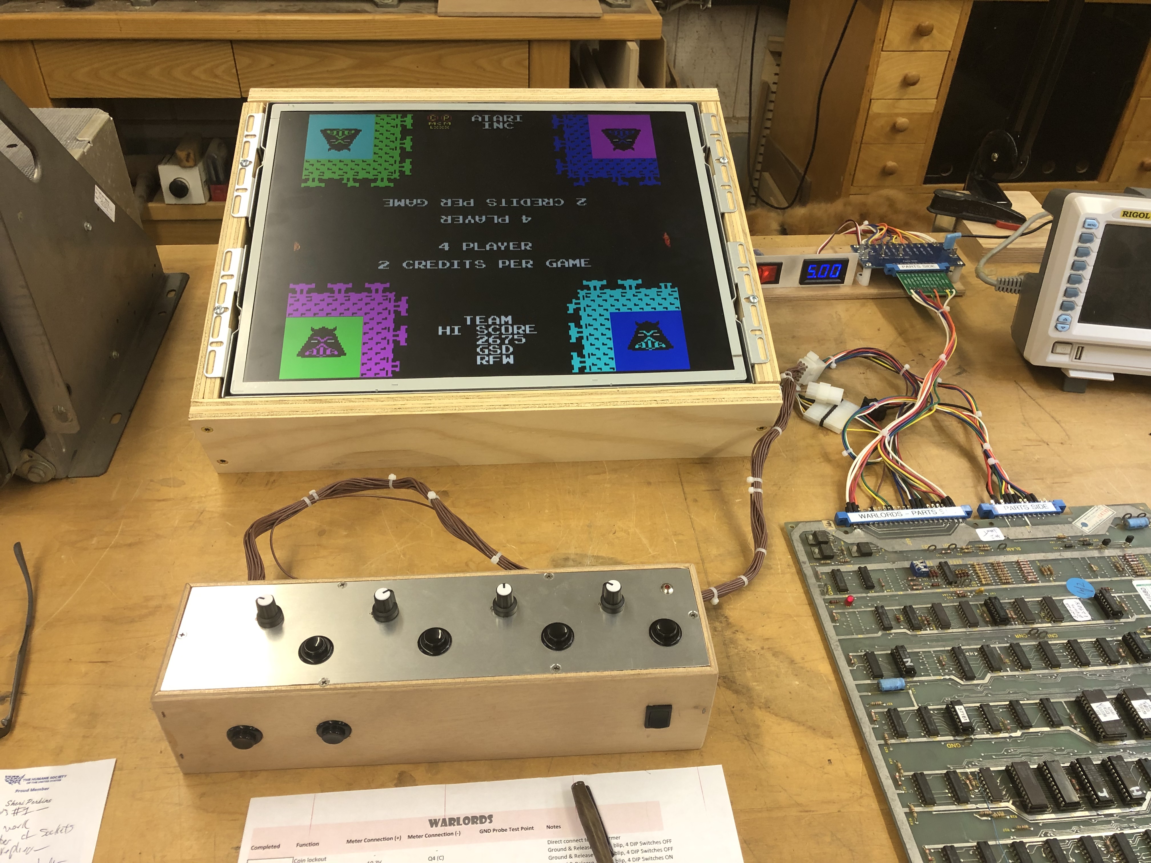
One other positive side effect of a new game with custom controls is building a new bench controller for it. This may be my first single use one.. I’m not sure if any other games using 4 x 5K pots.. I have a controller with an analog stick that uses them (Star Wars, Red Baron). We’ll see what pops up.
Board works!
Board #2 – In for repair
Triage:
- Prior work – solder side trace repairs and jumpers
- Edge has had a repair
- Weird resistor hack on C8
- Some sockets replaced
- Screen a little small
- No sound

After all the initial board maintenance, the first time connecting the board the screen seemed small. These Post-it notes show where the playfield was on Board #2 vs. Board #1 (shown). First thing I checked was the HSYNC frequency which was a little off.. Went right to the crystal from there – it had been replaced with the wrong one. 12.000 MHz vs. 12.096 MHz – which doesn’t seem like much – but it is the amount of the overlap on the screen.
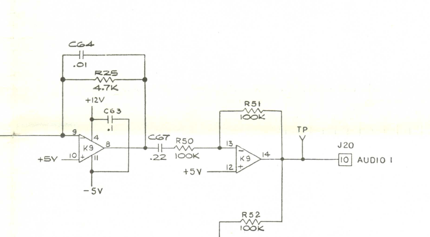

No sound: Thankfully it was a busted C67 and not the Pokey. Sound restored.
I connected up the controls and the first pot wasn’t working. Turned out to be prior work. Pin8@A5 was not soldered to the trace on the back of the PCB.
The last issue is that all of the shields are offset from where they should be. The color of the shields is controlled by the video memory address since they take on the color of their quadrant. You can see when they get outside just enough the shield changes.
I poked around a while to find this, but I knew it was in the Motion Object – Horizontal section. I could even trick it by grounding a counter – Pin7@K7 and make the Player1 shield move to the correct spot.
In the end – it was bad prior work again..
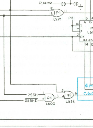
The PLOAD signal should come in Pin5@N9 – but never made it to the LS32. It got to N9 by connecting to this pin above.. But that trace is not actually attached. Corrected the work. I’m going to go over more of the prior work and clean it up.
*** Update *** – Day 1 of burn in testing – Pokey died. 😦 – Replaced Pokey.
Board works!
Board #3 – In for repair
Board came in with RAM errors, but I was told it had been sitting a long time.

All chips removed and cleaned, Deoxit the legs and cleaned up the edge connector.
Once the maintenance was completed, powered on and RAM was shown bad in self test. Connecting to the PCB – ROM was all good – Showed RAM@3K and @3H as bad. Socketed and replaced the RAM which corrected the issues.
At this point I did my standard 12 hours burn day1, then power cycle test a couple days later and 12 hours day3 a couple days later. Surprisingly – no additional failures.. Boards that have sat for years often have that issue.
Board works!
