

Board #1 – In for repair
Board reported as not booting

Step 1 is to build up a bench adapter for my test rig. Takes a couple hours but once complete, I can switch PCB’s in seconds and I’m always certain the power, video and controls are 100%.
The PCB had minimal prior work, but many tarnished chips. Performed routine maintenance, removed cleaned all chips and Tarn-X on the bad ones.

Seems to have cleared it all up.
**** Updated
One of the reasons I have a 4 day test cycle is to shake out weak chips. My third day of testing consists of a hot/cold power on 30 min, power off 60 min burn in for 16 cycles (24 hours).
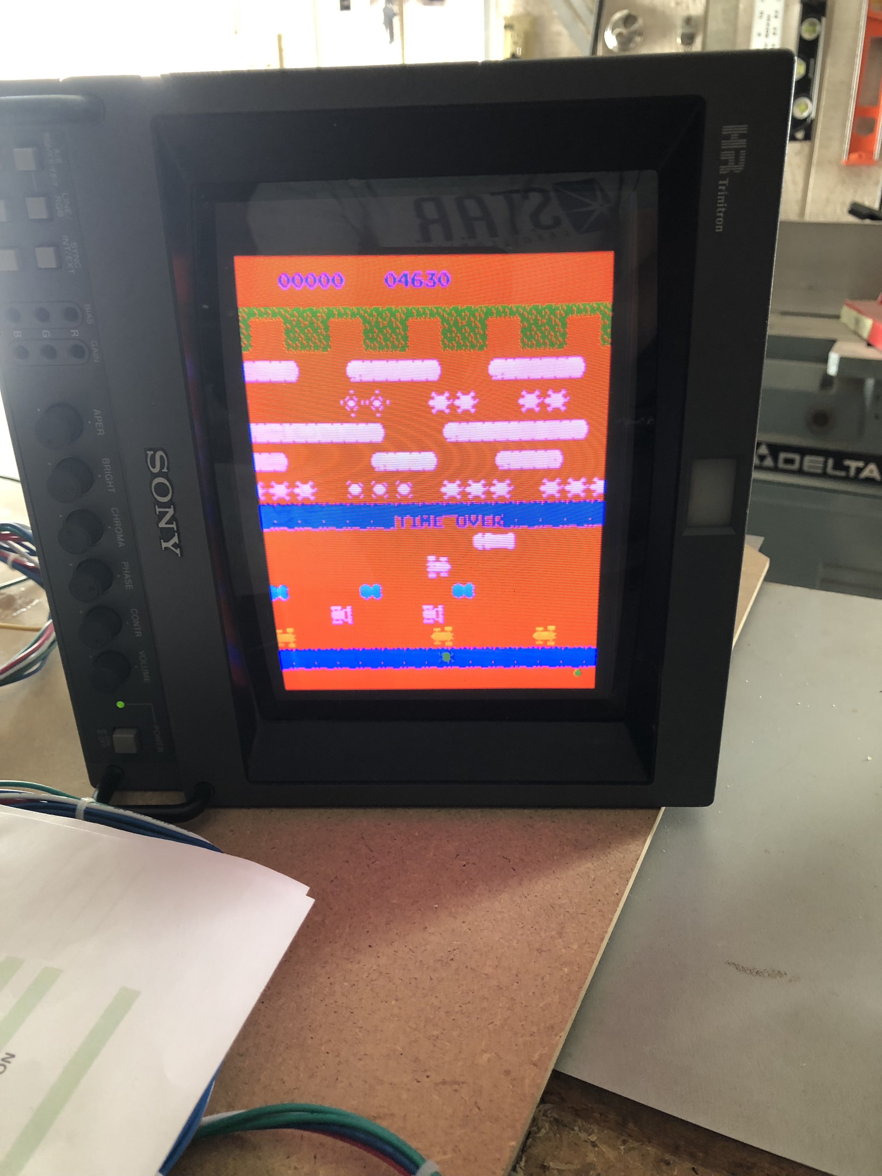
The result was a red screen a day later. Found a bad RAM 74S201N@IC60 – a 1 bit RAM chip. Replaced.
Board works!
Board #2 – In for repair
Reported no sound.
After full maintenance – board has no sound as reported. It also did not always boot. Sometimes it would boot to garbage and I had to power off/on a few times to get it to boot.

Working backward through the circuit.. I first suspected the amplifier, but the wet finger trick on the solder side showed it was fine. Having a working board helped me learn the circuit better.
The sound chip, AY-3-8910, is only getting 2 of the 3 signals at pins 27, 28, 29. Pin 27 seems to be dead and it appears to be software controlled. My prime suspect was the 8522 PIA@IC40 didn’t seem to be working.
Replacement 8255 showed up in about a week and I piggybacked it @IC40 just to see if it would make a difference, it didn’t (yea.. it was a long shot). I continued to probe around making to see if there was a better way to be sure this was the bad chip.. But everything led back to it..
Pulled.. socketed.. installed new PIA. Full sound is back! It also started booting cleanly. This PIA is on the address bus with the Primary Z80 CPU and since it was not working correctly, It makes perfect sense it was effecting the boot process.
Board Works!

Board #3 – In for repair
This one came in reported not working. It ended up with me at the lake and got the chip cleaning, board maintenance before I started testing it..


The big item found during inspection was this exploded tantalum cap in the sound amp area.
Powered up and everything worked. Completed full 3 days of testing w/o issue.
Board works!
