

I picked up a Star Trek S.O.S. a little while back and it’s moved to the front of the line for cleanup and rehab. I’ll cover it in a separate thread.. At the same time I’ve been helping a friend restore a Captains Chair that had been 60-1’d.. It’s getting pretty close to done. The stack that came with my cabinet needed a little work and I have an extra stack to work through.
All that said – the G08 worked on the bench when I first fired it up.. I planned on maintenance and a recap based on the condition of the rest of the cabinet.
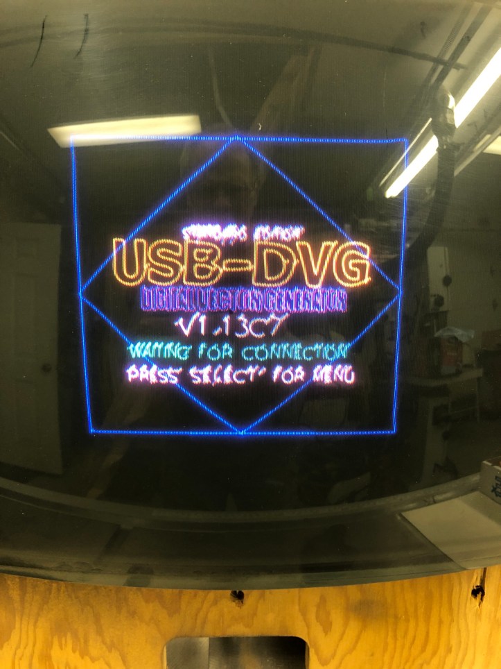
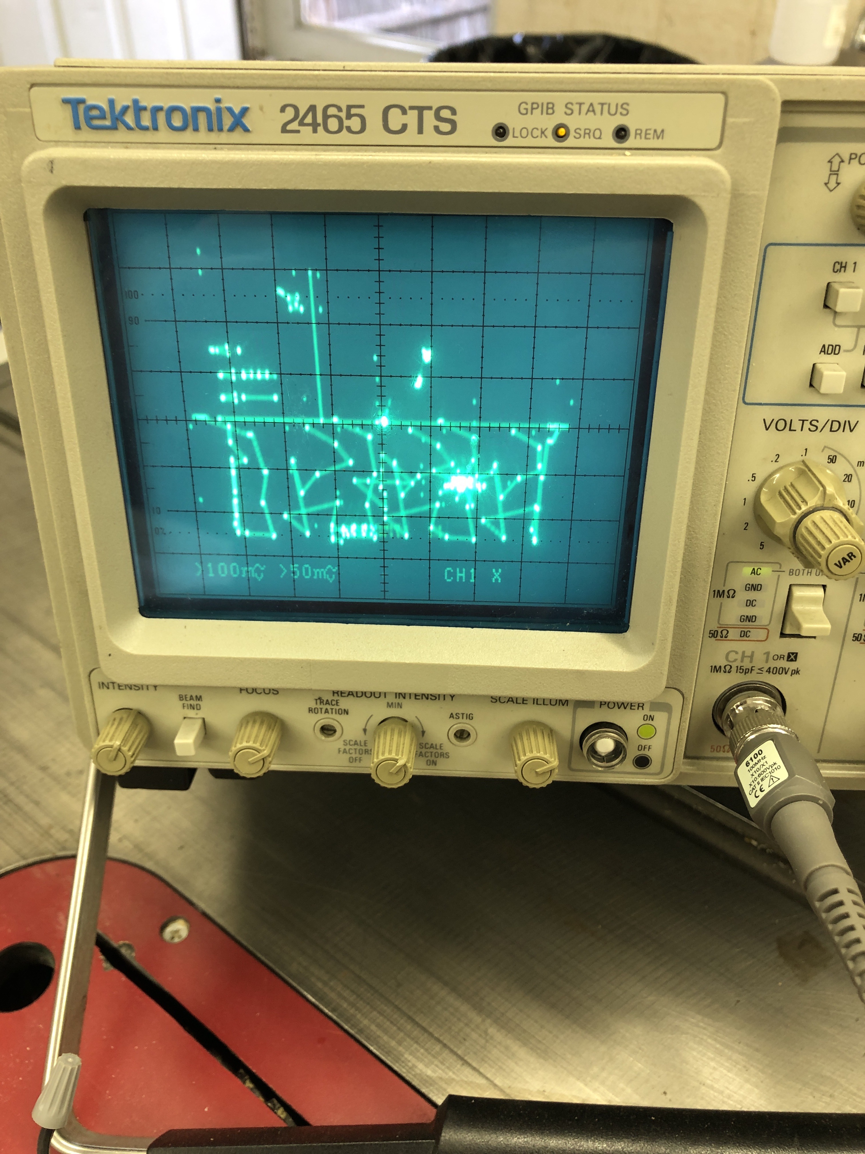
Before doing anything – we had been trying to isolate issues with The Captains Chair – boards vs. wiring vs. monitor. The engineering team had a USB DVG for testing – so I connected it to my G08. On The Chair and my G08 – we got this same shrunken image with distorted vectors.. The DVG works correctly on an Amplifone.. After a lot of Googling and checking and asking – we could not make this work correctly on a G08 and I’m not convinced it was ever tested with one.
The next part I’ll take some responsibility. While trying to get the DVG to work – I was stepping through the menus and somehow created the equivalent of a bad X,Y board. I just started to hear the deflection overdriving as I changed settings buttons and then Boom. It was too late..

Catastrophic failure. I’ve worked on a few B&W vectors and a handful of raster – but this is the first color vector for me. I’m not a complete noob, but in no way an expert. I’m just starting to know what I don’t know on this one.

I had planned on maintenance work. So while I wasn’t happy about it blowing up, it wasn’t the end of the world. I found the focus wire hanging by a couple of strands and it was very short in length.. Lucky I had a couple donor TV’s available.. the second tv I opened had the perfect 20KV replacement wire.


Recapping was already planned and as far as I can tell – the monitor was original. It had some work on it, reflowed pins, etc. But not too much prior work.
I’ll make a list of mods at the end – the one that seemed sensible was to repin the KK connectors and to replace the deflection headers. The round header pins seem like an easy failure/resistance point. While I was there I added key pins to the paddle boards. The headers are keyed, but the paddleboards were not. They are real easy to offset by a pin.
Q603, a couple of the 2N6529’s, paddleboard resistors, and a paddle board transistor checked bad. I checked every single transistor and diode I could after getting the deflection board all repaired. Connected it all back up. BOOM….. The 700 side blew up. Ughh..
After further review – I had missed a bad transistor on the 700 side paddleboard (I believe). However now everything was suspect, including – did I get cheap Chinese power transistors?
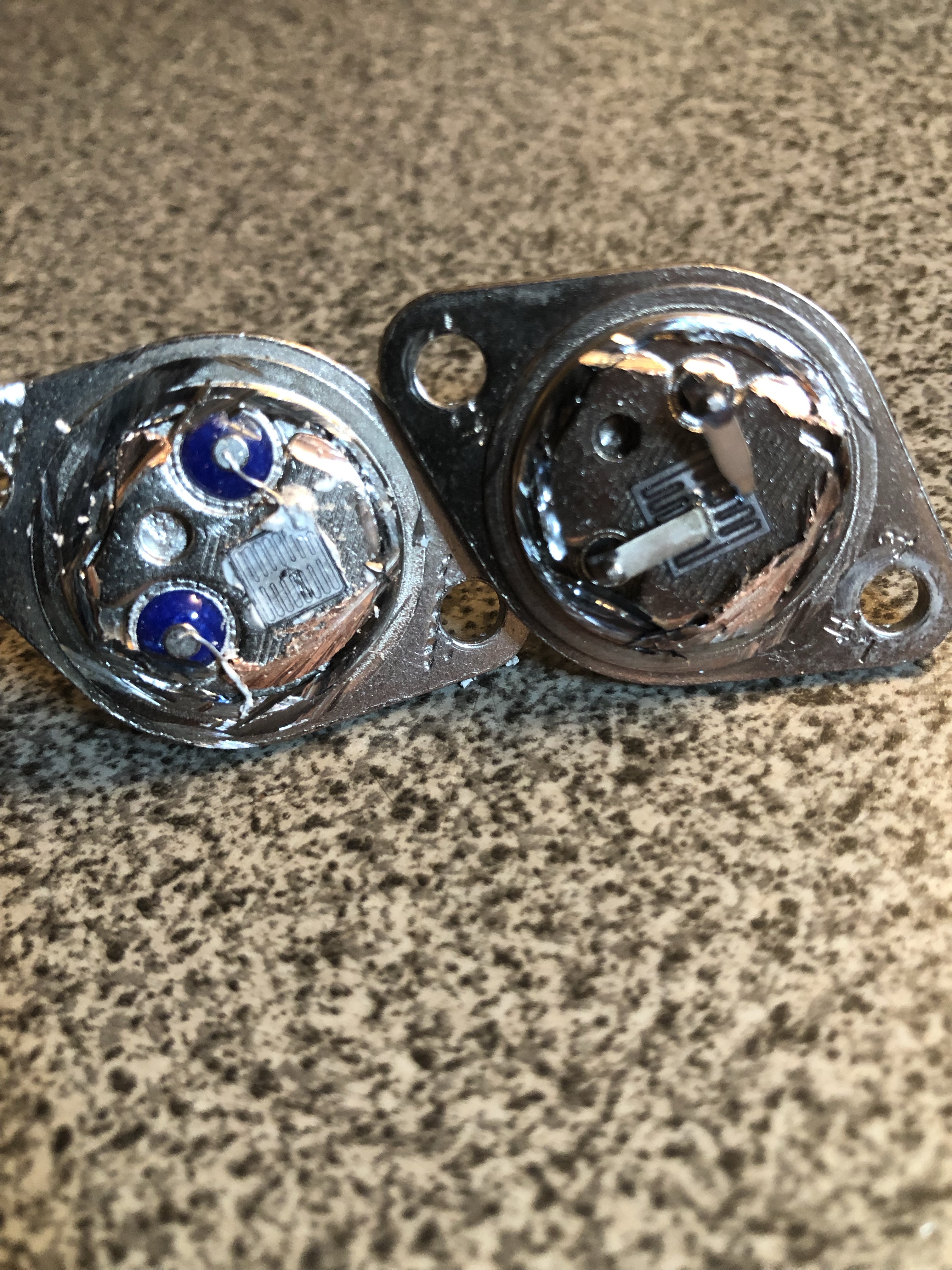
New on the left and original on the right. In hindsight, I do not think they are cheap knockoffs. Just modern manufacturing techniques.. But it was fun to cut it open and look. I did go to the Bitronix Star Trek Site and spent some time reviewing recommendations. Second time around I went with MJ21196G power transistors just to be sure. I now have plenty of extras of both types that I hope I never need.
At this point I decided to really dig in and figure out a better way. I’d seen the How to Bring up a 6100 Guide by @AndrewB and looked for one for the G08. It doesn’t seem to exist as a whole, but the information was out there in pieces.
But first – Maintenance, debugging and repairs:
My Power up Sequence evolved out of research, testing, screwups and debugging to get the monitor working. It’s the destination after this journey.
After the failures, I went through and tested all of the transistors and diodes in circuit … again. I’d also checked all of the big ceramic power resistors and anything that looked like it was designed to get hot. Some components I had to lift a leg to make sure they were good because they didn’t test well in circuit.
I replaced all the round pin headers with new square pin headers for the paddleboards and the yoke.
When I replaced the power transistors, I used SILPADs instead of the mica and paste. Those transistors get very hot. Later I read a recommendation that on those, even with the pads, use the paste. After touching them – I agree. I’m going back to add the paste.
There is a mod that has you reverse the transistor so that the bottlecap is inside and the wiring is on the outside. I’m not a fan of it personally as having those connections exposed makes no sense to me. To me the heat dissipates from the flat part of the transistor – not the cap. I’m going to laser it and see.
The foil on these boards is very frail. I inspected it closely under the magnifier to look for cracks. It’s very easy to mess up with the desolder gun, etc.
On the schematic, F600, F700 show 3A fuses. The Biltronix site recommended 2A fuses and the PCB shows 4A fuses. I put 2A SB fuses in and they invisibly blew at some point. I had not noticed and chased that for a while before I came up with the power on test sequence below. For now I’m using the 4A fuses, but maybe I’ll try the 3A later.
The deflection and HV unit were in and out a number of times. I found it much easier to disconnect the focus wire from the neck board vs. the focus pot. A positive side effect was for testing, I didn’t have to keep connecting and disconnecting it.. I covered the exposed end with tape and made sure it stayed away from anything while powered up the HV unit. Once I finally got the guns firing, I reconnected it.. Without the focus wire – the screen will be just a fog of out of focus colors..
I was convinced I had somehow blown up IC600 (the deflection custom chip). Since they are unobtanium, I picked up a second deflection board from Vector Vault and crossed my fingers that the custom on it was good. After cleaning, testing, reflowing, etc. It did the exact same thing as my original deflection board.
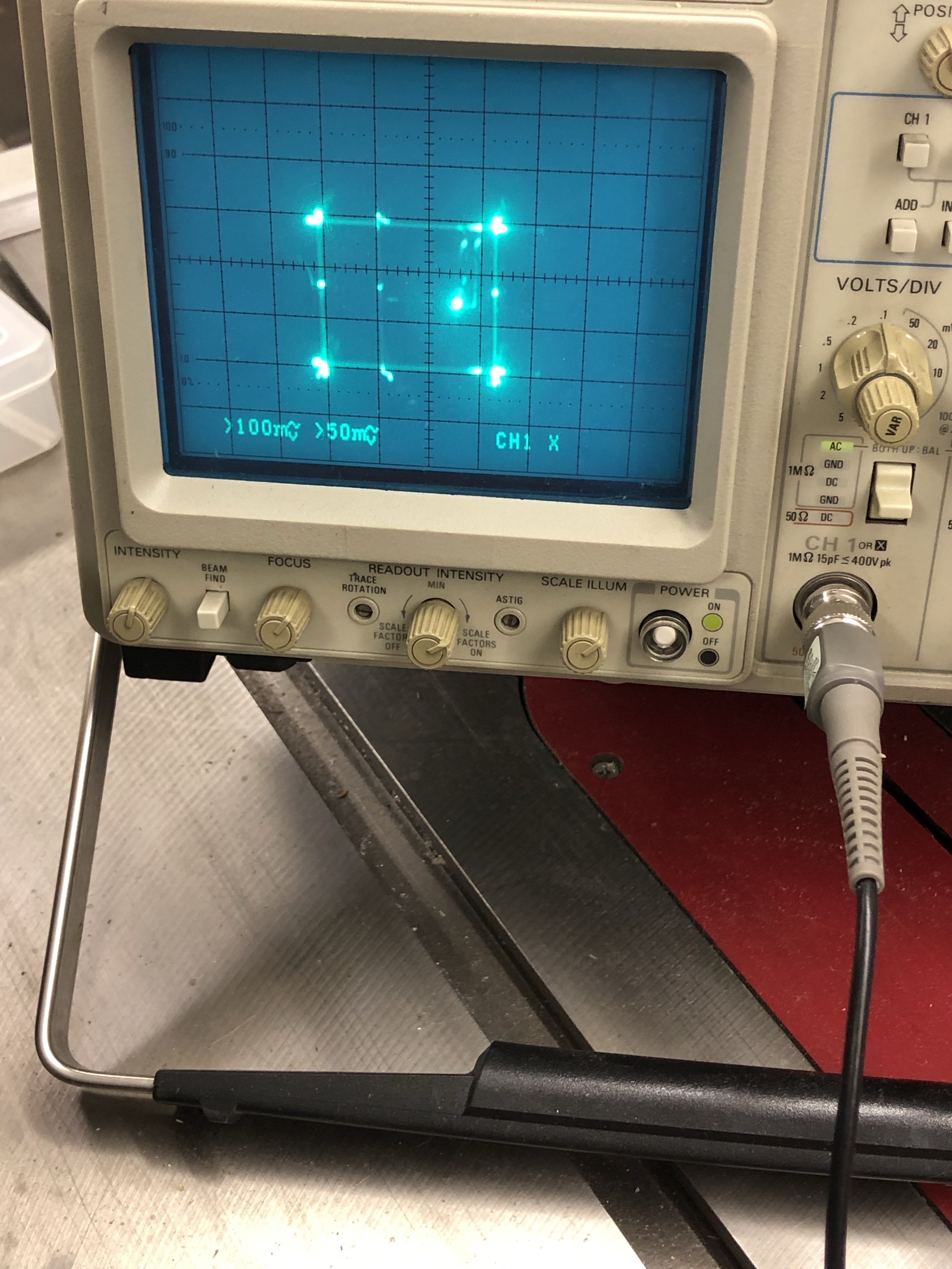
Above are the inputs to IC600 (perfectly good Star Trek) – The best way to check this is to clip on to the resistors just before the custom IC600. I clipped to the tube side of R602 and the paddleboard side of R700. This told me X,Y were getting all the way from the stack, through the limiter board, connectors and to the deflection IC. So far so good…
On the right is what I thought the output was from IC600. I had clipped onto the first resistors on the output side of the chip. IC600 does pincushion correction, etc. But obviously that is way more than pincushion correction. Initially I thought I got unlucky and the second IC600 was bad too.. but the chances of it being dead “identically” to my board was next to zero. The head scratching continued. I had the right idea – but tested at the wrong spot!


What I SHOULD have done is checked for X,Y output at PINS 1,2 of the 10 pin HV connector. Testing here comes after IC600 and works it way through the all the circuits. The game is upside down and backwards and I had to adjust the divisions – but clearly I have a clean signal on the output side of IC600. Had I done this sooner, I’d have saved a lot of time and focused on the HV side of things. The upside is I have a perfectly working spare deflection board! I figured this out long after I had the monitor running.
My problem at this point: I seemed to be getting proper deflection, just no image on the screen. I was getting HV at the anode cup and I could hear the screen power on. Prior to ‘the incident’ the HV board was running AND I was getting HV AND I was getting a picture.
At the time I decided that I had deflection and even if it was crap – I should be able to see it. So I started on the HV unit.
Checking the voltages at the connector to the HV unit (not connected) they all seemed to check out. (See table in Power up Sequence below)
The HV unit will not create actual high voltage without the XY inputs from the game. It is the G08 equivalent of the Atari ‘Spot Killer’.
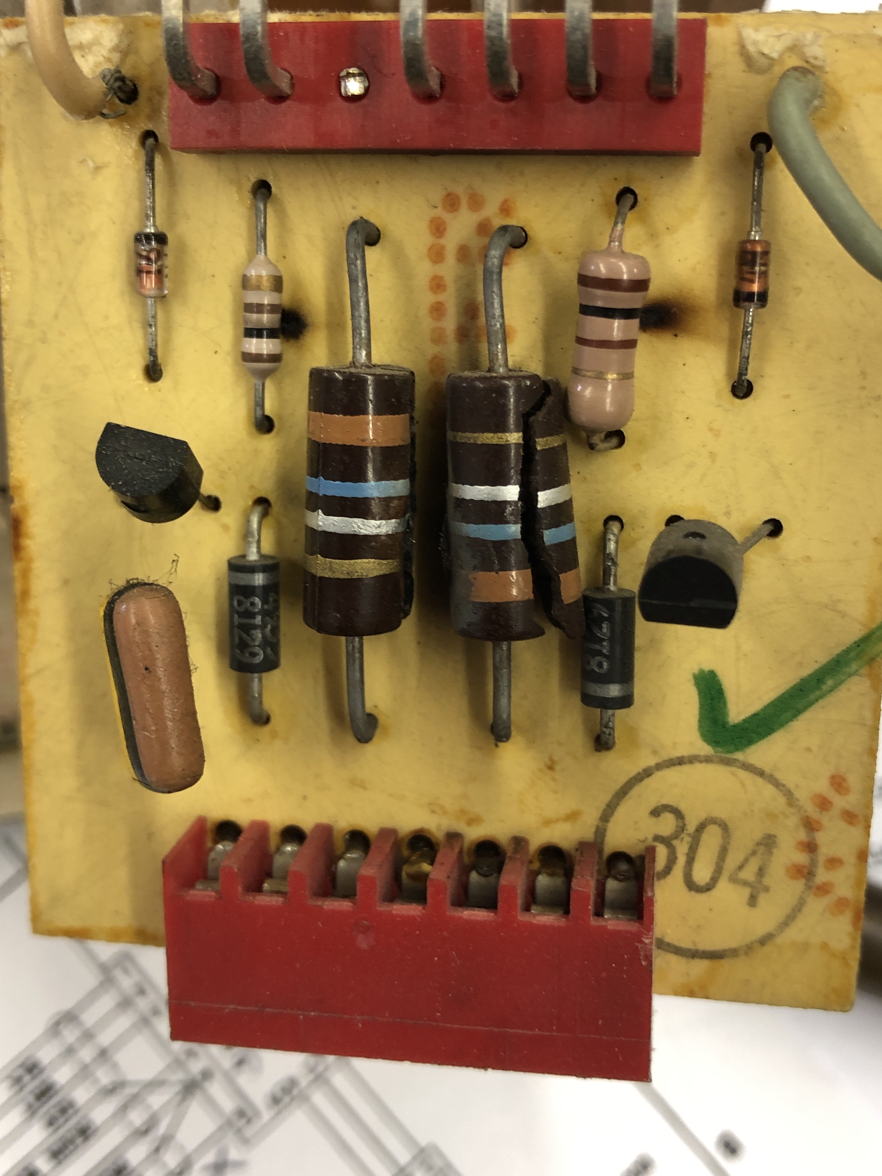
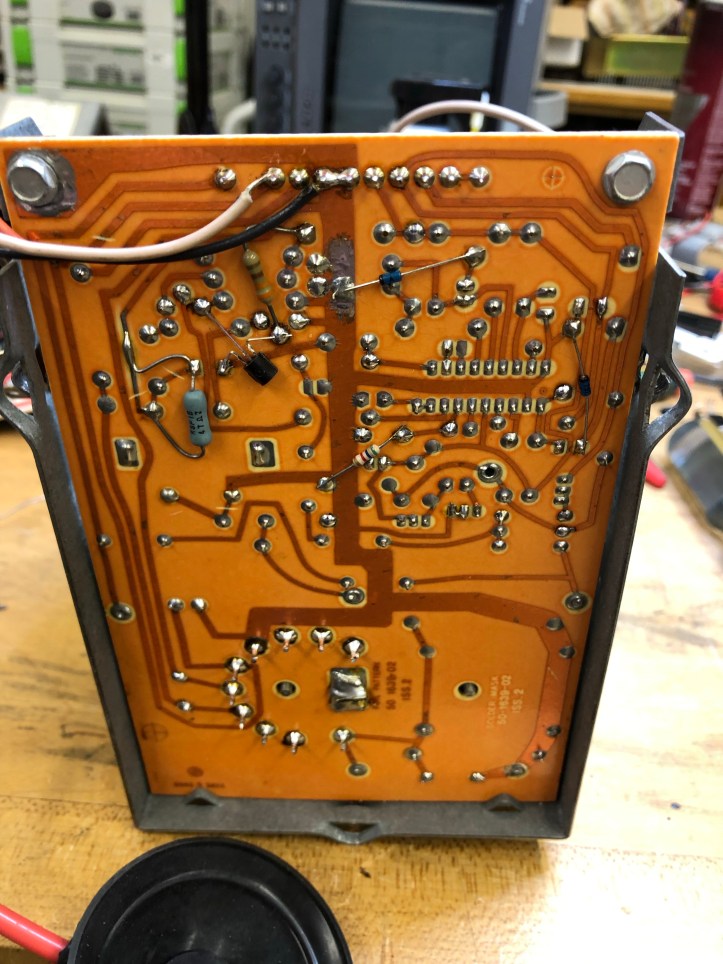
There is a small voltage regulator board on the side of the HV unit. It basically takes ~126vdc in and is supposed regulate to +100vdc. Testing with the video input disconnected, I had strange things happening and I could not get a steady 100vdc or anything within the recommended range 100v (-6v, +2v). To isolate it I removed the red ‘OUT’ wire from the header and I could check it directly. The transistor that is off the edge and screwed to the frame (Q322) is set up to fail and pull the foil off the back of the regulator pcb. Once isolated I got 100vdc (and I had to mess with the traces a bit as they were lifting).. Adding a pin as TP2 worked great.. Once the HV unit is in place it’s a pain to recheck w/o the TP2 Pin.
Since it had been working previously, I added the video connection and the 100v regulated destabilized. The heater voltage was not reading 6.3vac as suggested. I pulled the heater wire (pin 7) from the Molex connector and then the 100vdc stabilized. It was my turning point.. no color from all 3 guns, screwy heater voltage.
Just to be sure – I checked resistance at the neck of the CRT – pins 9,10 – phew.. it was good .8 ohm – but not open! I’d already checked Q901, Q902 and Q903 in circuit. The HV transformer generates the heater voltage and it is a very simple circuit.
I got a bit scared that somehow IC900 got messed up? no way.. The important output is at the collector of Q902. With TP1 connected to ground with a test lead – you should see this:

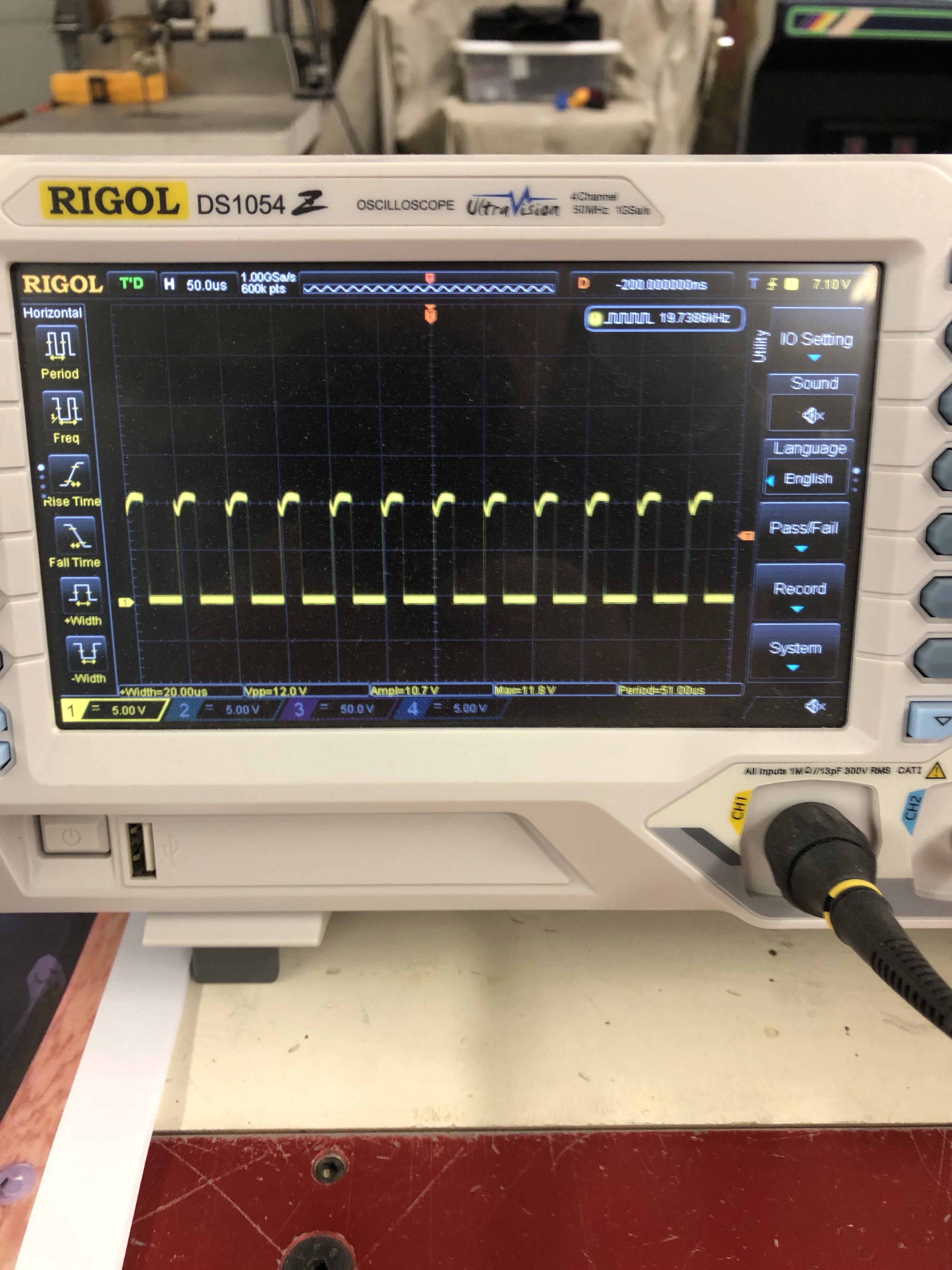
Later in the calibration the duty cycle gets adjusted. The import part is IC900 is oscillating to generate HV on the transformer.
Q903 is the 2N3904 on the back.. checking voltages against the Sega manual showed it to be significantly off. I removed it and checked it out of circuit and it tested bad.. Progress!
I replaced it and got fuzzy color on the screen for a short bit (focus wire was still not connected).
Connected everything up and still nothing.. WTF..
But getting color for a bit made me focus on heater voltage again. The KK connector to the HV unit had been on/off 20+ times and should have had a good connection.. That said, I used some 220G sandpaper and sanded flat spots on the round pins and replaced the pins in the Molex KK with Trifuricon pins. (Note: I later replaced the header connector on the HV unit)
Plugged it all in and got it working. Phew.


I made a bunch of mistakes working on this monitor – but I was determined to figure it out. There was a lot of checking, cross checking and odd stuff I’m sure I missed above. The outcome was that I believe I have a pretty good power up sequence that can limit the blast radius of starting up an unknown G08 in the future. I’m certain this is old news to many – but I’m a lot more comfortable bringing the monitor up in stages now.
I still get a little nervous when I power it on. That will fade with time. I’m certain I’ve made it it a bit more reliable.
