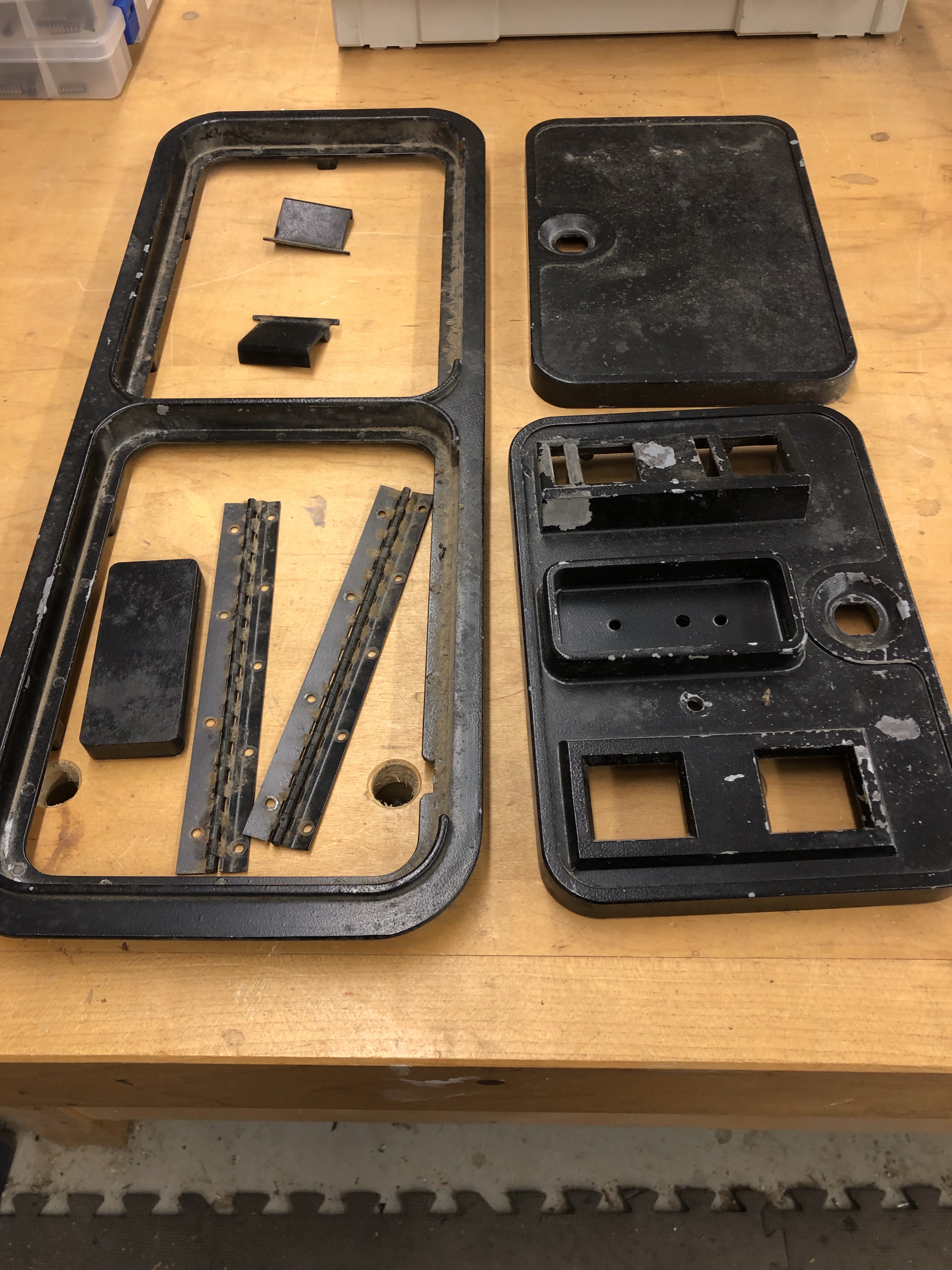
The control panel had the same oxidation as the rest of the internals.
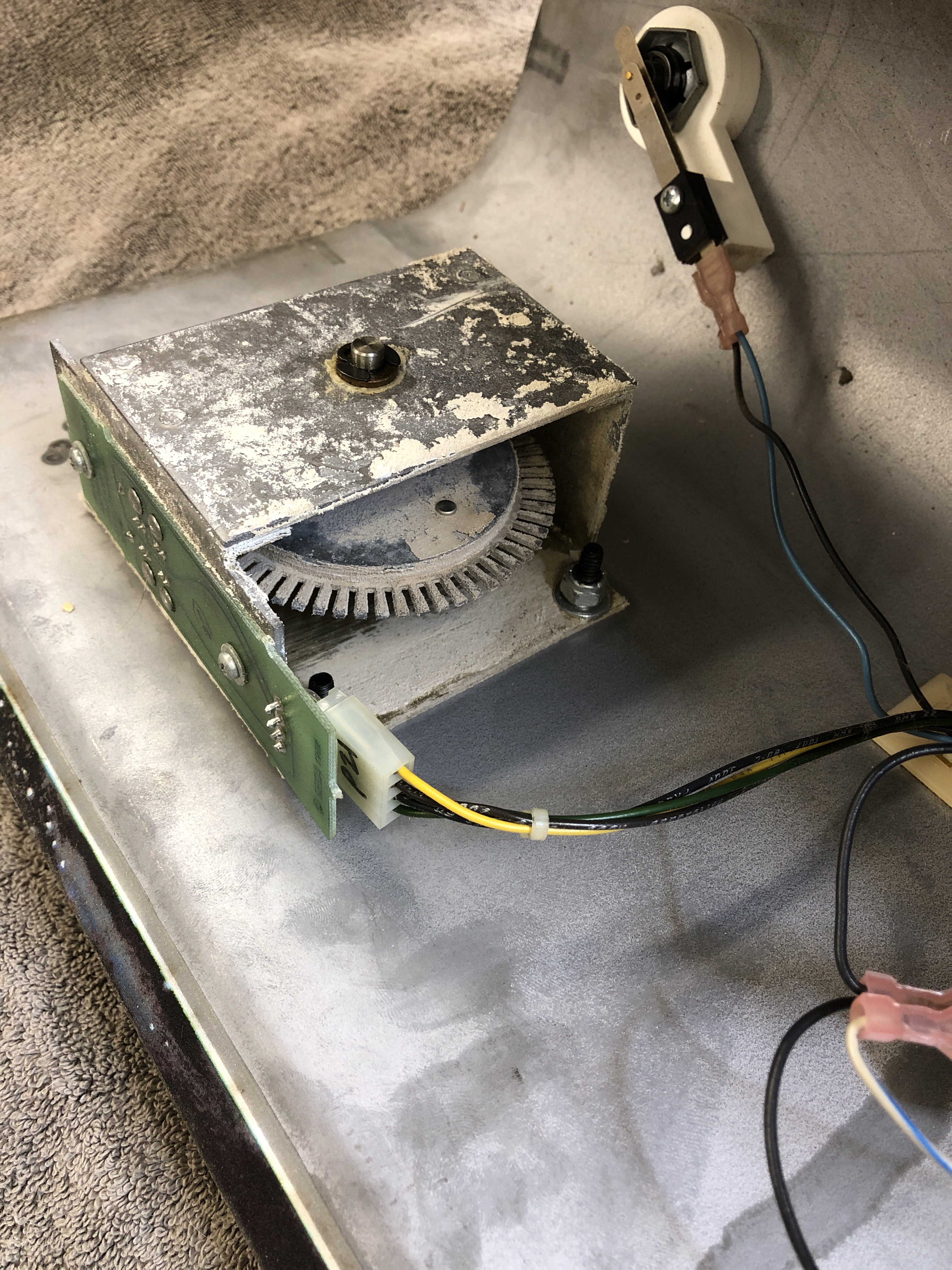


I messed with the spinner for quite a while.. Once you take them apart they really do not like to spin freely once put together. After about an hour of cleaning, reassemble, test, disassemble, repeat. I determined what it wanted..
The flat part of the outside of the bronze bushings seemed tight and were binding on the E-clips. I flattened them a bit with 600G sand paper and removed just a tiny amount of thickness.. I also ‘flattened’ the E-clips with a hammer on a flat metal surface (my tablesaw). They flex/bend just a hair when being removed I believe. Looking at the clips, they are shiny where they rub the bronze. The good thing about bronze, it wears in, not out.
Last step – spin for a few minutes on the drill. Problem solved, nice flywheel motion now. The clips and the bronze wore ‘in’ together again.

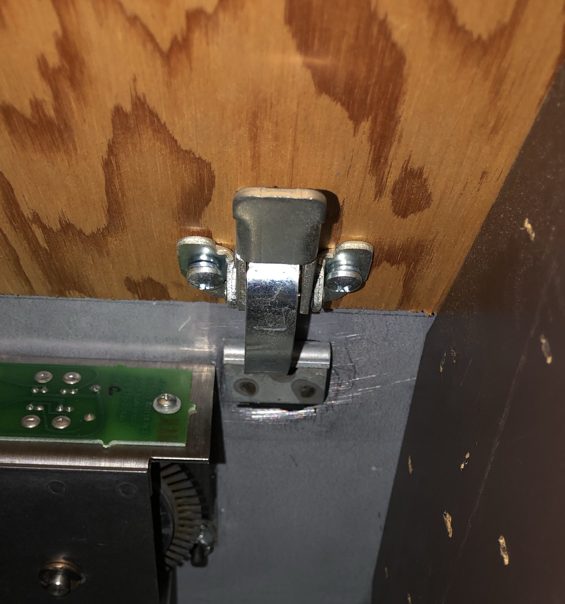
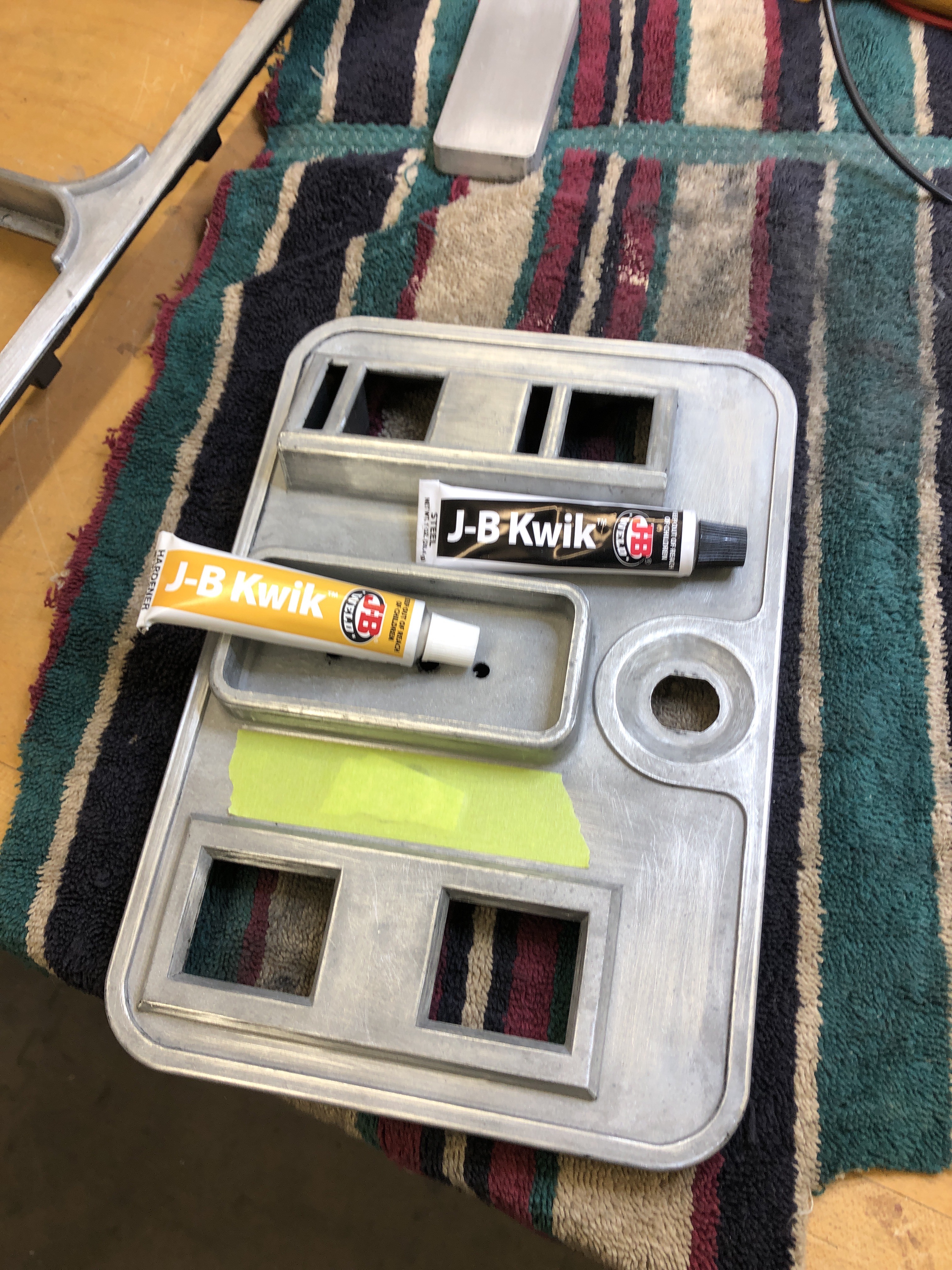
This metal clip was also in the bottom of the cabinet. The spot welding failed. It is from the side of the CP that got crushed. I can’t weld it back without ruining the overlay. I tried 3M5200 to glue it back, it failed miserably – I was surprised. I’ve had great luck with it in the past – but it really is not for steel on steel it seems. JB Weld on the other hand worked fantastic! I scuffed it up with 80G paper, cleaned with alcohol. The CP retaining clamps pull pretty hard and the JB Weld is holding up. I like it!

Buttons and everything cleaned up nicely. The overlay is original, it’s in A/A+ condition. There are a couple of small marks on the front. I’d expect more wear around the spinner. Couldn’t help myself – the carriage bolts got sanded and painted.
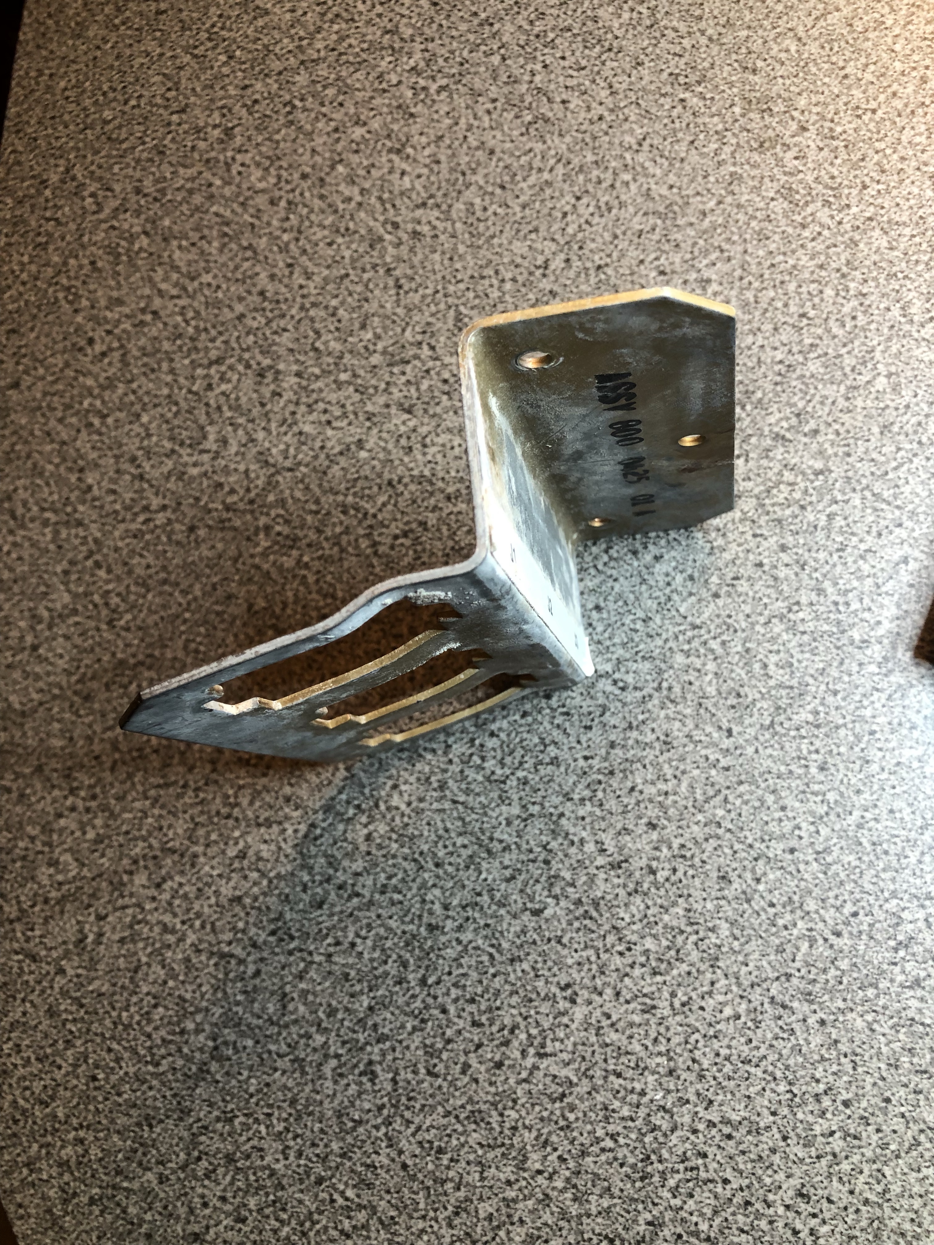

Part of cleaning up the PCB cage – the bracket that holds the AMP connectors was all bent up. Hammer + vice = fixed.
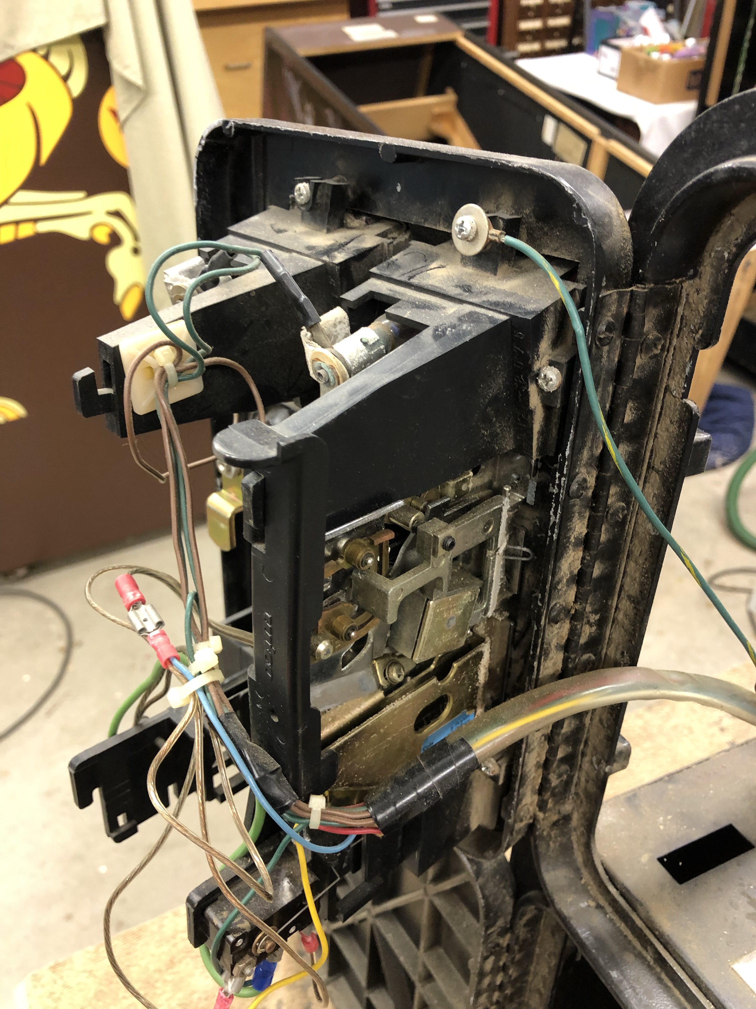
This coin door is terrible.

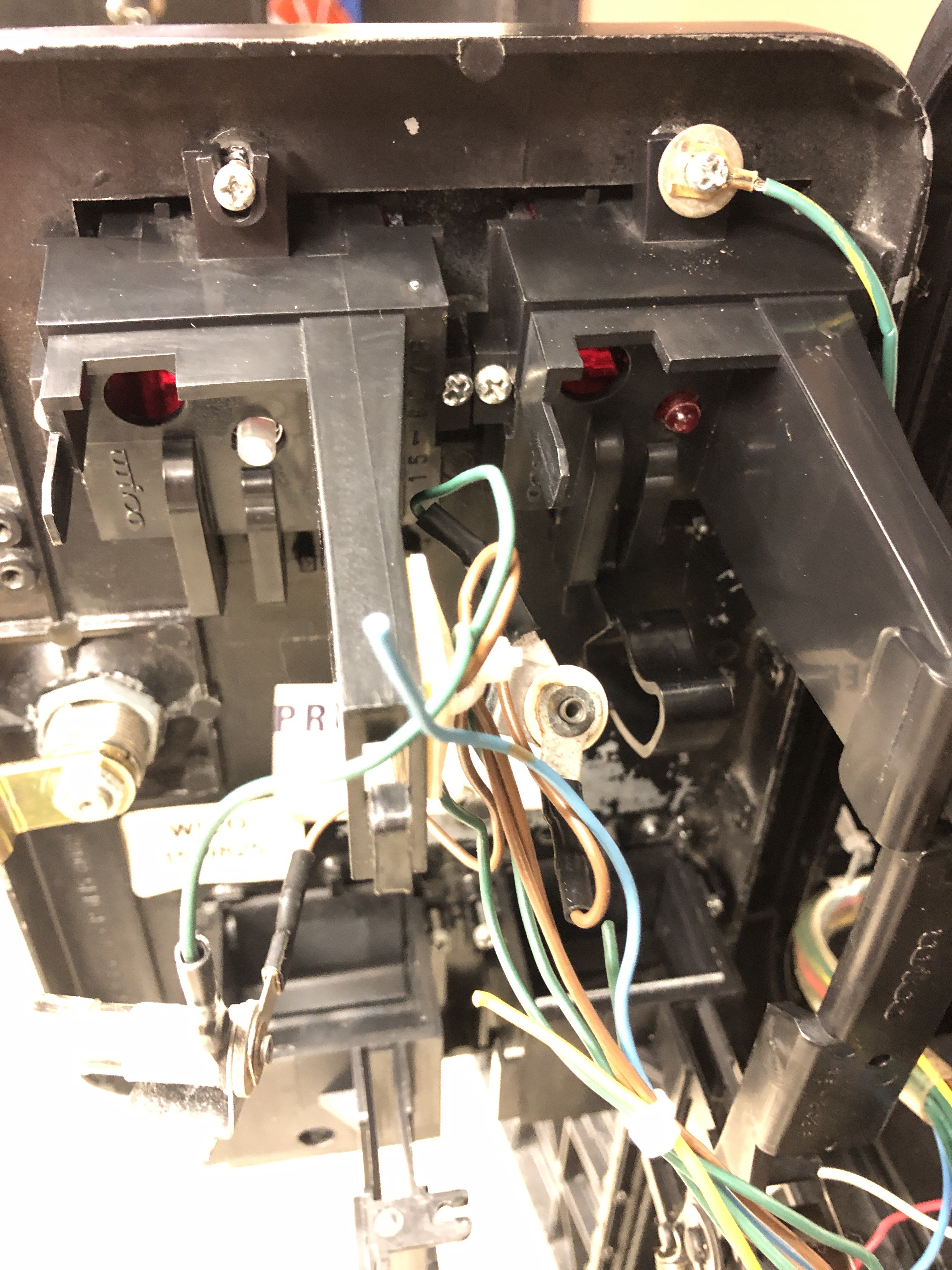
Original paint is peeling off, a coin switch was drilled through the front. Parts of the right coin mechanism are missing. The right coin slot and reject button are under that black (tape) actually. They were jammed into place.

There was a coin button drilled into the second coin return. Plus the wire hacks that go with it all. I’ve done a number of coin doors now – they can be made to look original. Unfortunately parts are missing from the right coin mechanism. Sourcing those has been problematic so far.

Step 1 – sandblast off the original paint. Only on the outside. No need to do the inside, it adds to the illusion of being original. I’d run out of blast media. The cash box door got finished after this pic was taken.
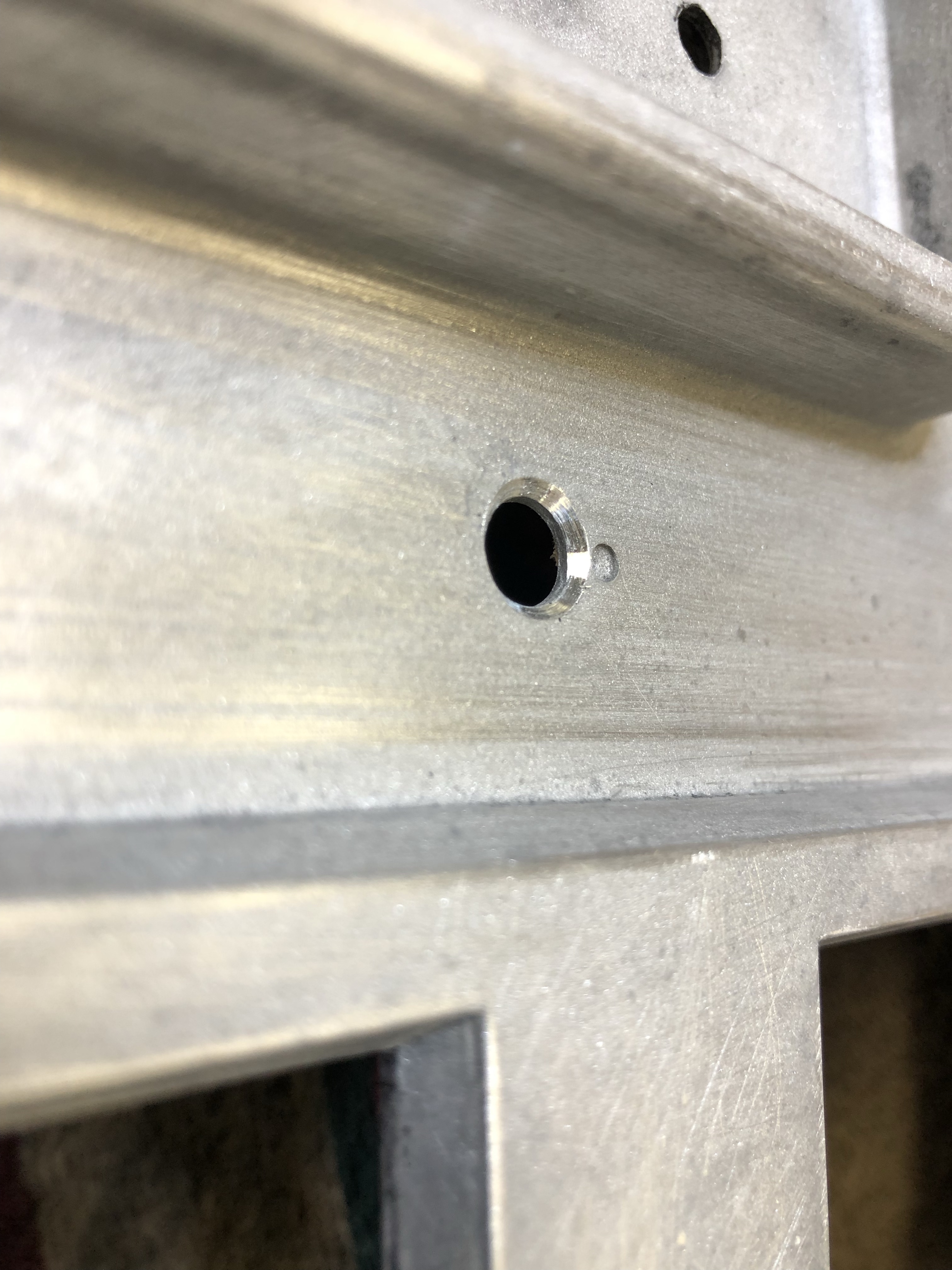
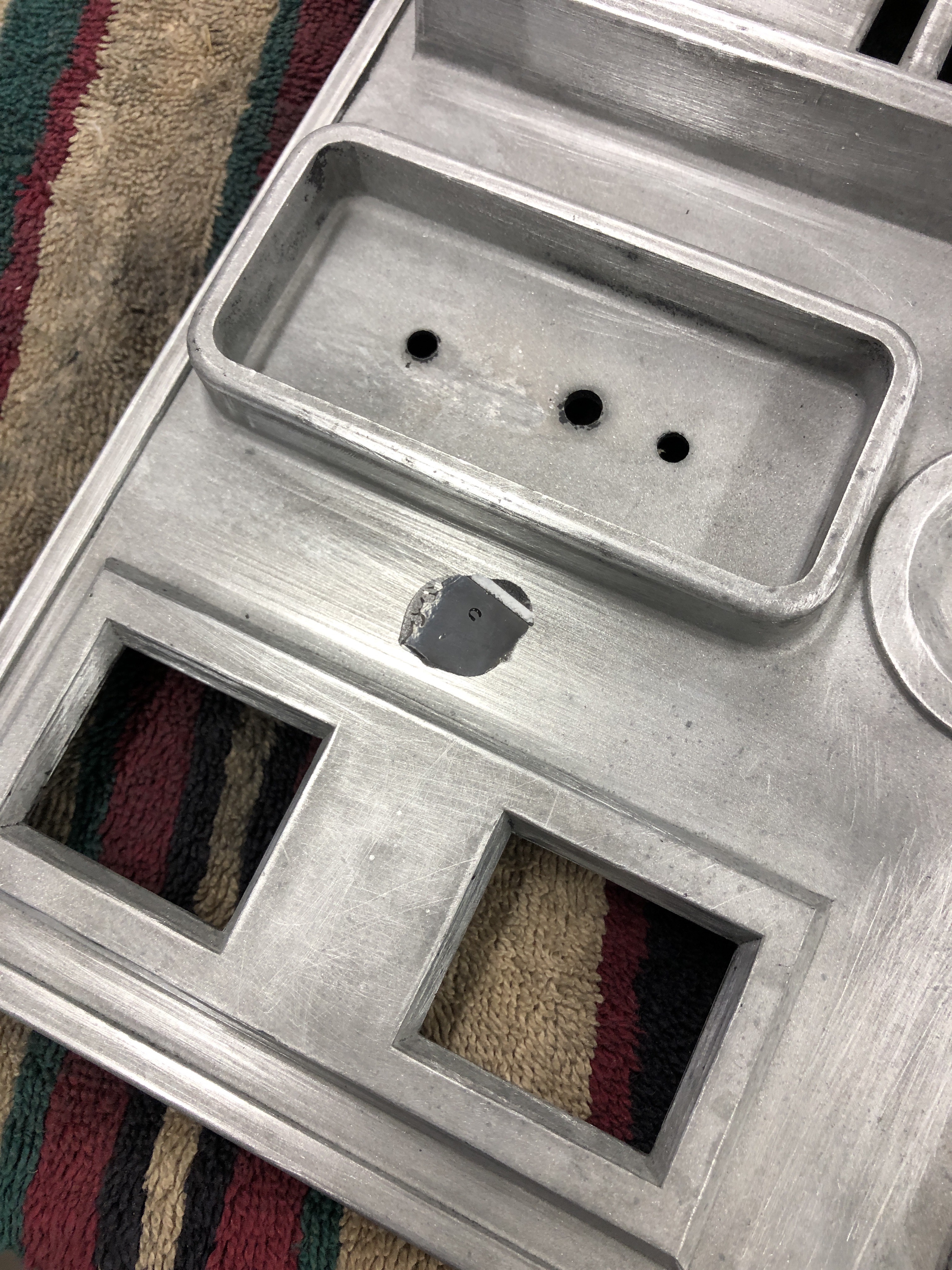

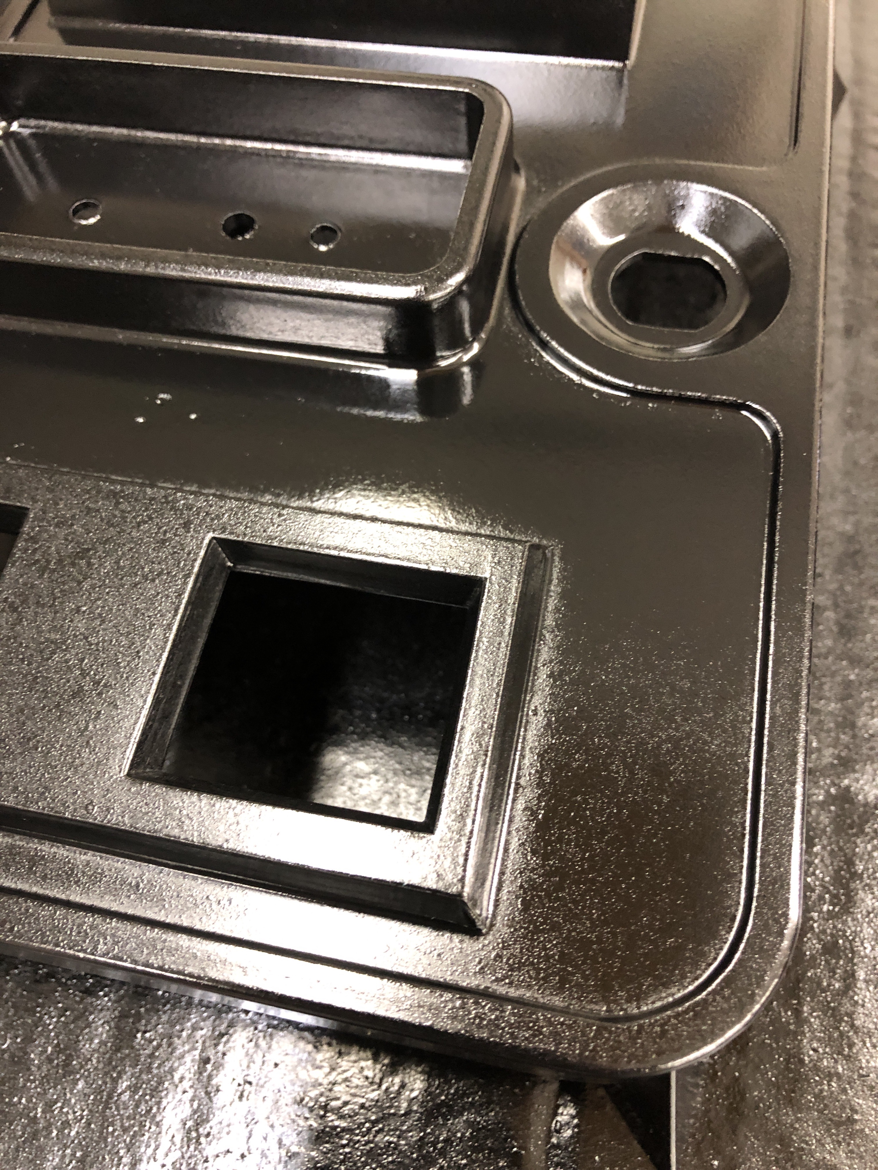
Fixing the coin button hole was pretty easy. Use a countersink bit and flare the hole from BOTH sides.. that leaves a narrow ‘V’ pointed toward the center so the repair can’t pop out. Next JB Weld and use some plastic from the packaging as a form taped over each side to leave a smooth surface. Sand it all flush with 320G paper. I also do a light finish sand with 320G on all the parts after sand blasting to clean up surfaces a bit more.

After all the prep work. I wipe the parts down with alcohol and dry with compressed air. My shop is kept at ~60 deg in the winter. I submerge the paint can (Rustoleum Satin Black) in hot water for 5 minutes to warm the paint. This helps with the flow and leveling in my opinion. Spray on a smooth bottom coat.
After 30 minutes, I misted on a fine texture coat. My Atari coin doors all have a heavy texture to them – which is actually more difficult to do because getting the can to spit paint like that is tricky. The Wico/Sega doors have a much finer texture. I just held the can a couple feet away and let the overspray settle. It came out A/A+

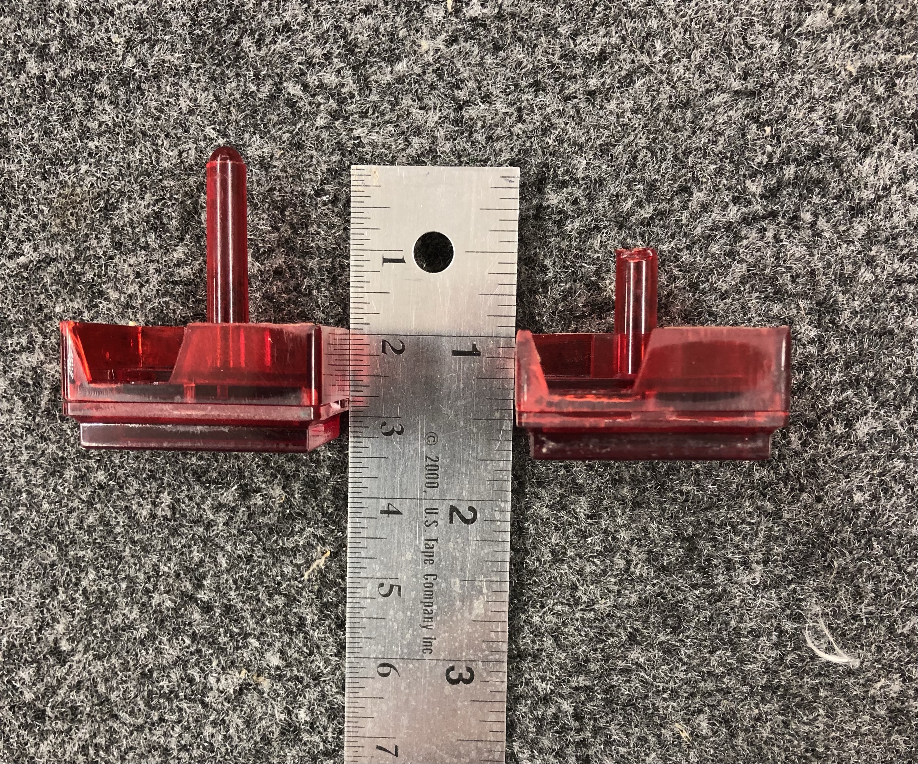
The left coin mechanism was complete and working when I got the machine. The right side had the hacks. It is also missing parts and the reject pin on the back of the button is half broken off. Here is a pic of all the left side parts I need to make the right side 100%. The original bottom return is fine – it had a hole drilled in it and the metal plate is missing. So it is a nice to have more than a necessity. I’ve searched and many of these parts are near impossible to find.
And then I got an idea…
I bet I can fix that original button.


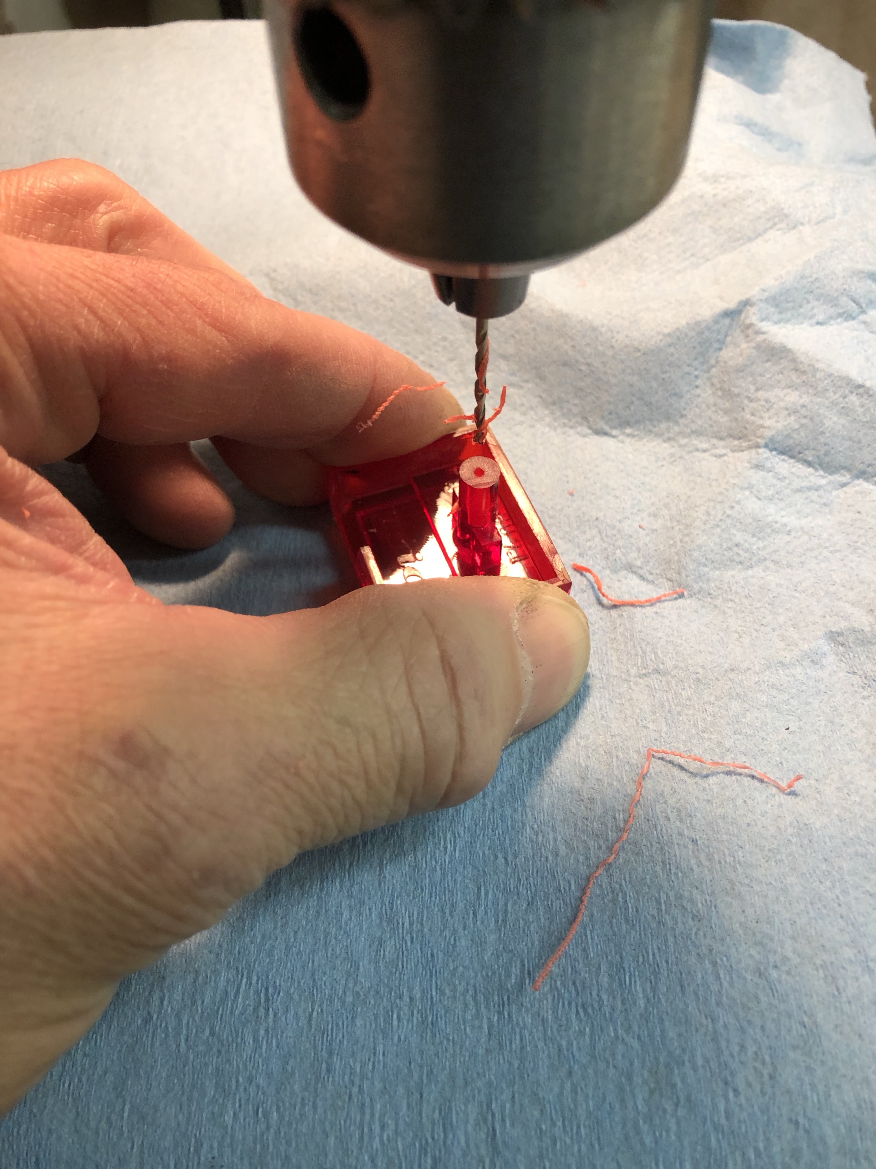
On the left – the end of a small artist paint brush. The plastic feels identical to the button’s in terms of hardness, etc. I clean cut the broken button stump and using the smallest drill bit I had – put a hole down the center of the button post on the drill press.


After that – I cut the end off the paint brush and drilled a centering hole. My tiny drill bit gave its life to this button. I cut it to length and used it to pin between both sides together. A drop of JB Weld to secure it, a little sanding and the original button is good as new. Maybe better – it’s hardened steel reinforced!
The proper amount of reject button exposed!
As for the other parts – I found the reject ‘porkchop’ at Arcadefixit.com. The hardware store had a suitable spring ($1.15). I ordered .25c push to eject inserts. Both button caps got wet sanded and Novus’d to remove the wear. A long arm switch for the coins is on the way. The only part I really need is the long plastic coin mech retainer. It is a candidate for 3D printing I think. If I model it in Sketchup – I bet I can get it done.

The harness was a little chopped up – but there is enough there to reconnect everything. Look at those original stickers? How could this door be in such good shape! 😛 The cashbox is even in mint condition.


Cooling fan from the back panel had a busted tab? Not really sure how that can happen. I was able to solder one on that worked with the cabinet’s connector.
Working on the monitor was an entire entry in itself – read about it above.
For the most part, all of the PCB’s in the stack worked. The sound board is the only one that has issues. All static. I swapped it with one from another set of Star Trek boards that I have to work on.
This last fix came after a lot of weird happenings. While set up on the bench working on PCB’s – I used the G80 power supply and transformer that came with the cabinet.

For just PCB repair, this worked fine. When I added in the G08 – I had all kinds of problems with 5vdc. Which is off a completely different secondary winding of the transformer than the G08.
I picked up a second G80 power supply off eBay to use as a bench supply. Connected it and the transformer connector shorted and welded itself to the header. All of the diodes, etc. all checked fine. I replaced the LM723 regulator and that seemed to correct the problem. (It didn’t in reality)
For the longest time I bypassed the G80 / 5v power with my bench supply. I’d also tried one of the recommended mods to restrap the transformer for 120v vs. 110v. That would not work, game would not boot correctly at times. There was a power loss I wasn’t understanding.
Fast forward a few weeks – I found the root cause when I was reassembling the cabinet. After putting the cage, power supply and transformer – that had all been working together – back together – in the cabinet… Smoke and sparks at the transformer header on the power supply – It had been working for a few weeks on the bench and the game worked when I picked it up… WTF?

The burned connector is the one that came with the cabinet, it was not the original. This is my reference pic before I started taking stuff apart. I’m normally very suspicious of prior work – but it was working! I had replaced the burned Molex with a new one after this was taken. The G80 power supply schematic is a bit misleading – the internal lug numbers on the transformer and the pin numbers can be confusing since the transformer lugs are not relevant, but I’ll blame me for misreading it. I had looked this over when I was cleaning everything.
The cabinet wiring diagram has it right. After finding a few more pics of this connector just to be sure I verified it correctly against the cabinet diagram and a friend’s S.O.S.
They replaced the wires backwards!
It should be:

The red group and brown group give the same AC voltages, so the 12v+, 12v- and audio circuits were fine. But the purple 5v+ circuit had the hot wires connected to ground and the grounds connected to the ‘hot’ side. This messed up the AC reset circuit and I’m assuming made the power supply run ‘backwards’? I was getting +5vdc and -5vdc, even though I get it was all wrong. I’m more of a 1’s and 0’s guy. Maybe the more analog savvy can fill me in.
Correcting this allowed me to re-strap the transformer for 120v – lugs 2,4 on the primary winding – providing the proper 90vac to the G08 and the game now resets properly.
Experience +1. Do I need to “Always suspect prior work – even if it works?”
Thinking about this even further, did all of the zinc oxide coating turn to dust from electrolysis?? It makes the most sense.. 14.6vac was connected to the ground plane. Not enough for anyone to notice. It had to have been this way for years. I’m certain that is what happened now. Another problem solved.
