
I’ve been fortunate enough to be helping a friend rescue a Star Trek S.O.S. Captains Chair.
The woodworking and restoration phase of the chair is nearing its end and it was time to transfer the electronics from a working upright to The Chair. Once the board stack got over to the chair – it decided to stop working. Of course checking wiring, connections and cross checking didn’t reveal a thing. After some remote collaborative diagnostics – my buddy shipped the stack to me to see if something had failed.

Full stack showed up in really nice shape. It should be – it was fully working.
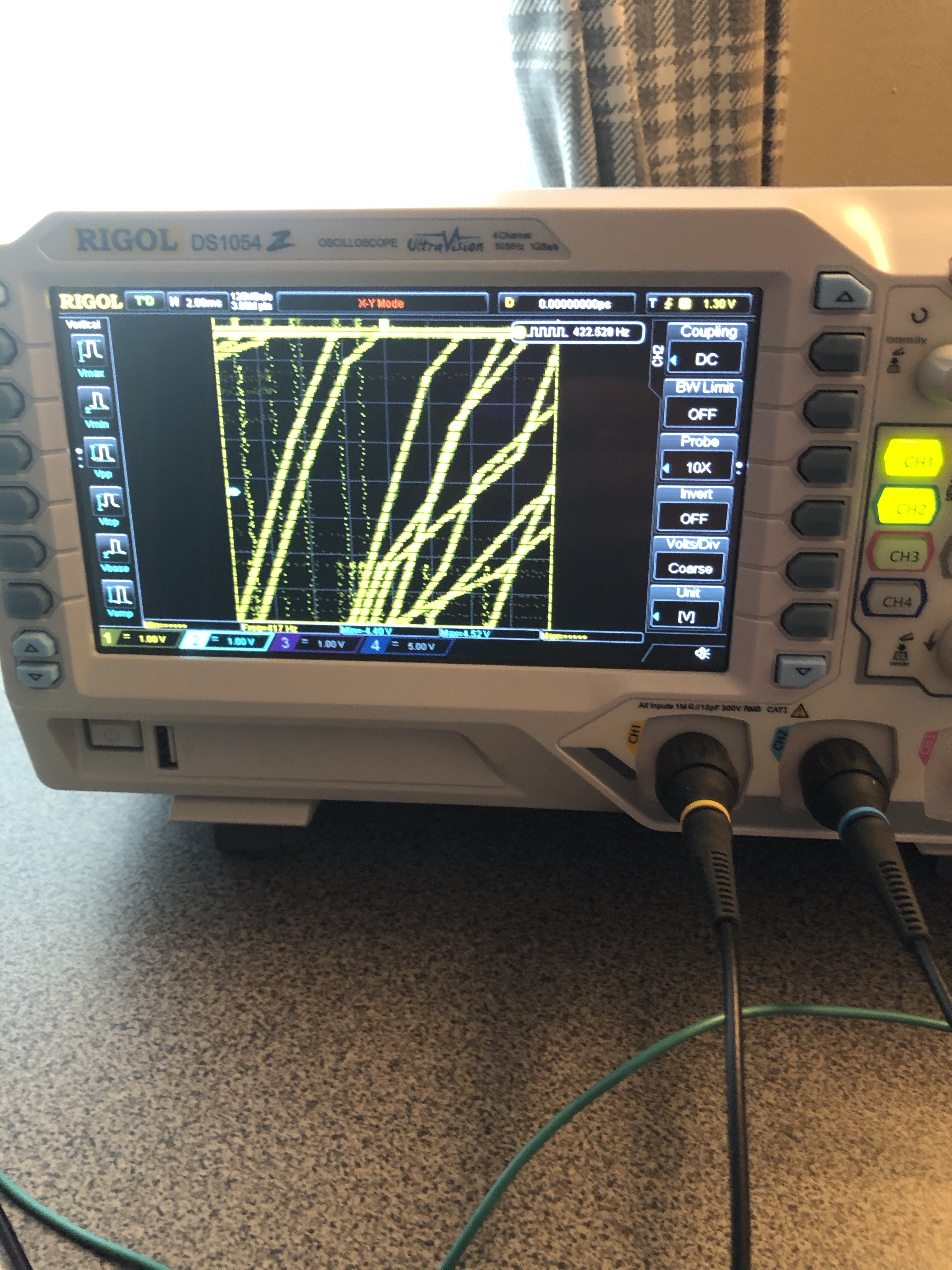
I’ve never worked on one – so it was a good learning experience. First step was to create a test setup. Best I was going to do is get it working on a digital scope. I don’t have a Star Trek cabinet or a G08 monitor.


I’m still in the process of setting up and designing a more permanent test bench. For this stack – my simple Jamma test rig wasn’t going to work. My power supply from my Defender cabinet had been refurbished (Defender cabinet is on deck to be restored) and it had all of the voltages I needed. I did have to do a bit of checking on the -12v because it was unregulated.. Only a few chips in the stack used -12v and they were all within tolerance of the -14v the PS was actually putting out. However – the +5v didn’t have enough punch and translated to about +4.3v on the board set. Not good enough.
Part of the stack uses a single AC voltage as a sense line to signal the first reset on powerup (it seems). It’s a little confusing on how much voltage should be going into the line. A bunch of online references say 3vac, the actual Sega power supply is showing 8vac and I only have 5vac coming off the defender PS. After messing around with it for too long and determining the CPU was being held in reset by this circuit – I moved the lead to 5vdc and the CPU started behaving like a CPU according to the logic probe.
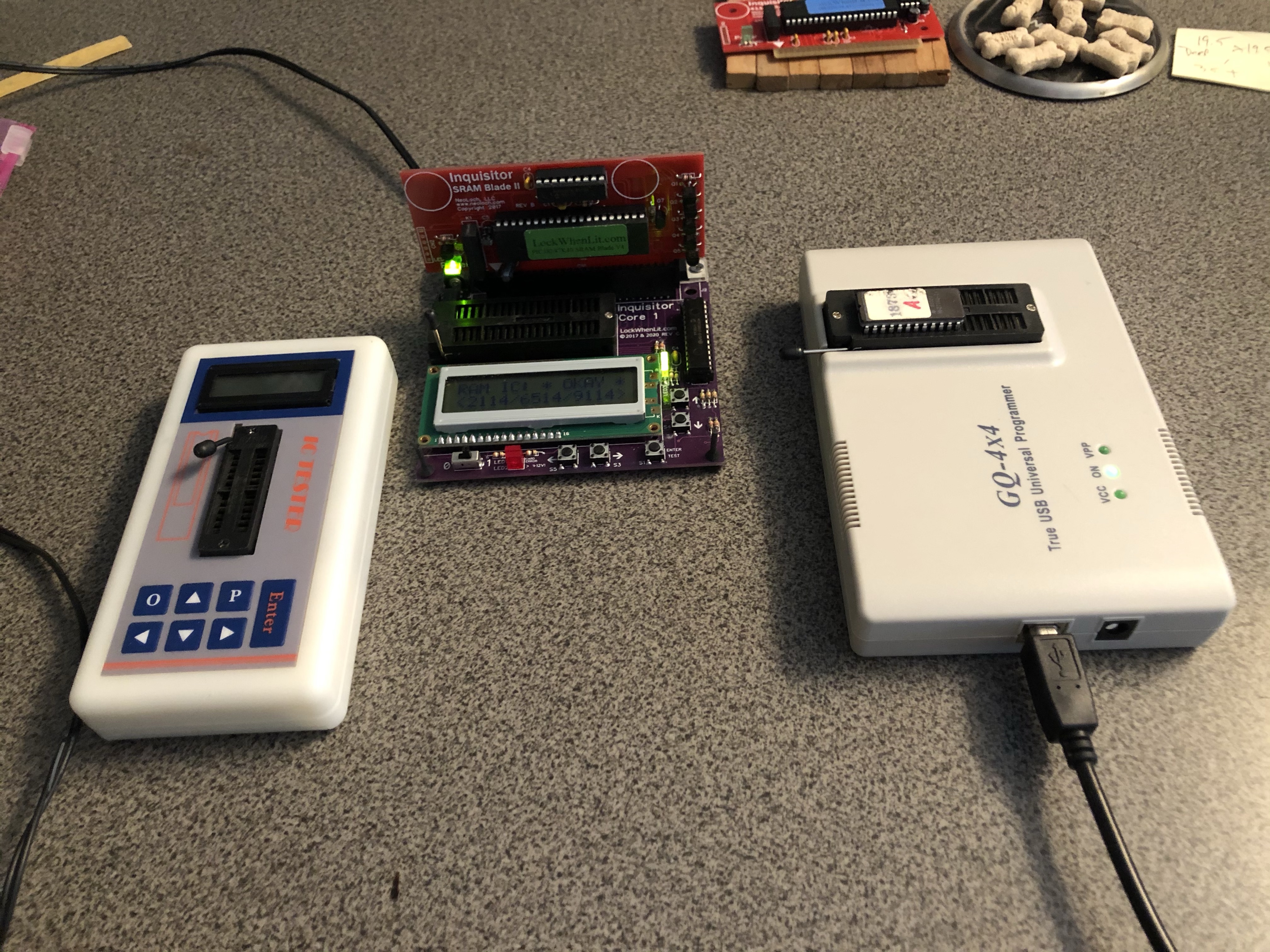

One of the first things I do is remove everything that’s in a socket and determine if it’s good. Everything checked ok as expected, except for an 74S04 that had been socketed and replaced at some point in its past. I pulled an 74S04 from another board and it checked on the chip tester (just because I haven’t tested many ‘S’ chips) vs. the original . I was testing the tester here. The swapped one checked out on the tester, so I installed it. It didn’t change a thing. Next I got a real bench power supply so I can manage +5V better. I see a few more of these in my future, very handy.


It took a while to figure out how the board stack worked. Parts of it seemed to be running and other parts seemed dead. I located the G80 Diagnostic ROM and that really got things moving. Once I plugged it in and ran with the minimum CPU and XY boards – the stack came to life. At that point I put the other boards in and everything started working. So – what was wrong with it? I’m not entirely sure. Maybe a finicky socket? I had the CPU board ROM and CPU in and out more than once.. It’s been solid since it started up. Stack works!
The fun part (for me) is that while the stack was getting to my house via UPS – a full S.O.S. stack popped up on eBay that we picked up. Having two sets of boards (even not working) makes diagnosis much easier. I had not got the good stack running yet when we got the second one.
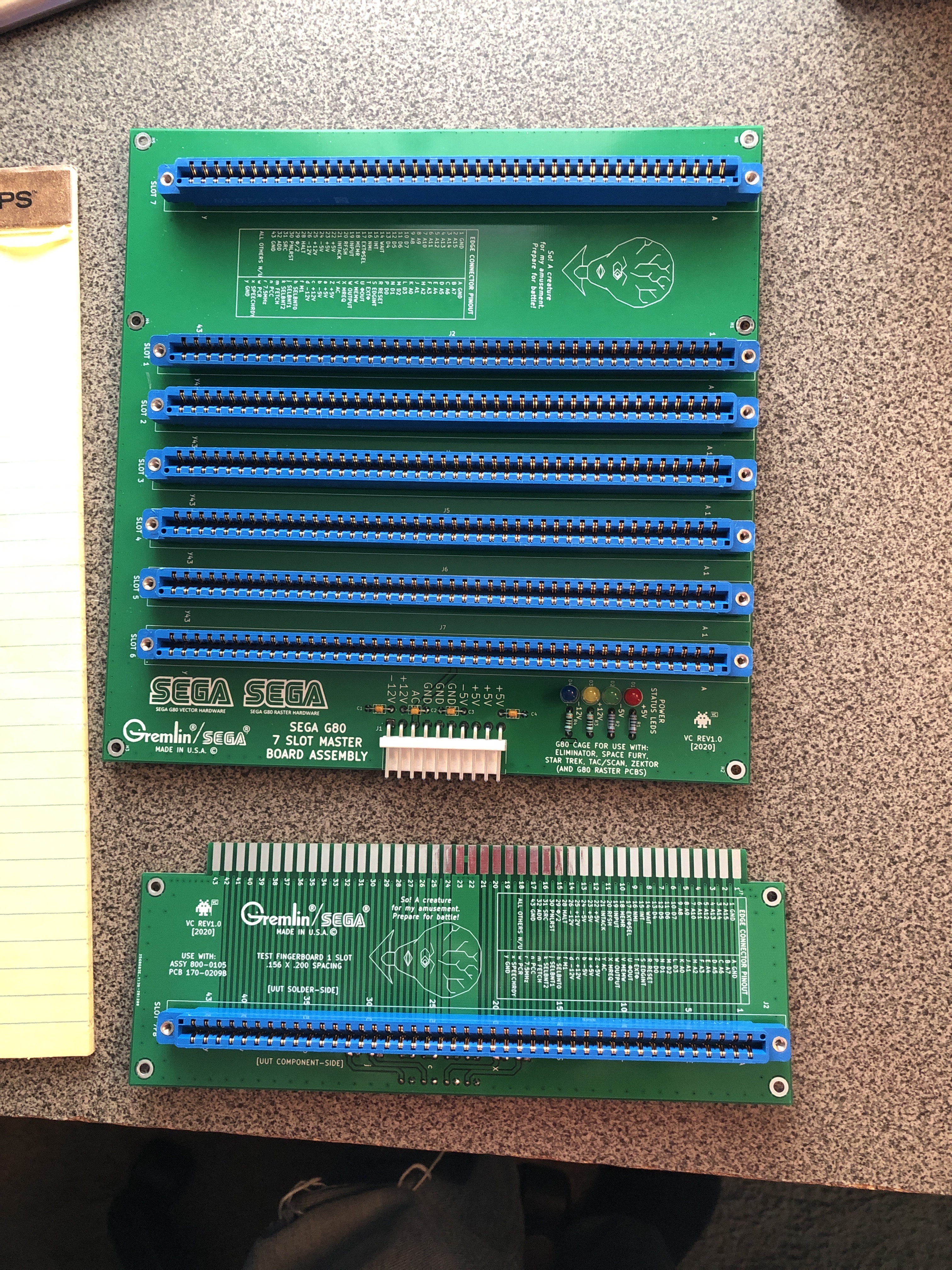

Well – now I was down the rabbit hole on these boards. Enter VectorCollector’s 7 slot backplane and finger board. Working on these is logistically challenging in the vertical position alone. Being able to get one flat was a nice change.
The eBay stack was visually in ‘ok’ condition. The boards had prior work and some were nicer than others. I pulled RAM, ROM and anything else that was socketed and bench tested them as appropriate. I swapped them one at a time into the working stack to unit test them as needed.
From here I’ll focus on each board in the eBay stack individually.
- CPU Board
- X-Y Control Board
- X-Y Timing Board
- Speech Board
- Universal Sound Board
- PROM Board
The eBay stack put up a good fight. Each board worked individually mixed in with the original stack as I repaired them. After I sent the first stack back to my buddy – I waited on parts to finish this one. Once I got the parts and re-tested this stack.. troubles crept in…
I’ll note this as: *** Burn in cycle ***
CPU Board
- Checking the RAM on the Inquisitor – had a bad 2114.
- Replaced bad RAM
- Board works!
*** Burn in cycle ***
I had not spent too much time on this one because it seemed to just work. Burning the board in revealed that there was more to do. Once I had the remaining parts and put the stack together – the CPU board decided to stop working..
Probing around revealed that the Pin16 INT was stuck high.. The CPU was not servicing interrupts. There was plenty of activity on the address and data lines, but clearly the game wasn’t running.
After considerable poking around and head scratching – since this board WAS fine – I happened to check the PROM chip at (U15). Poor and intermittent activity out. Sockets? Sockets. Seemed pretty solid – but I decided to replace it and the EPROM socket (U25).
Now the symptoms changed. Much more activity on the scope and very strange signals on D0 and D1.
It turned out to be my first experience with signals fighting each other – but took me a while to figure it out. Long story short – D0 and D1 shorted replacing the socket. ughhh.. self inflicted wound. The upside is I know what competing signals now look like and how to quickly find a short on a buss. The same 2 data lines furthest away from the short read .6 ohms (chip U1).. as I worked my way closer.. the resistance would drop.. .5 ohms, .4 ohms.. the actual socket read .2 ohms from D0 to D1.
Pulled and resoldered socket – board works (again) – original issue was the PROM socket.
Not to long after this – the board was still a bit flaky. It would run, then not run after a power up or being moved on the backplane. This turned out to be a flaky socket for the custom chip (U21). After replacing it – board has been solid and running for hours on the bench.
X-Y Control Board
- Got lucky here – worked out of the box
*** Burn in cycle ***
On the first stack – I didn’t test this board because I had no real way to test it (so I thought). However – we think it may be the real issue with that stack since we still have no colors on a known working monitor. Remote diagnosis is tricky 😉
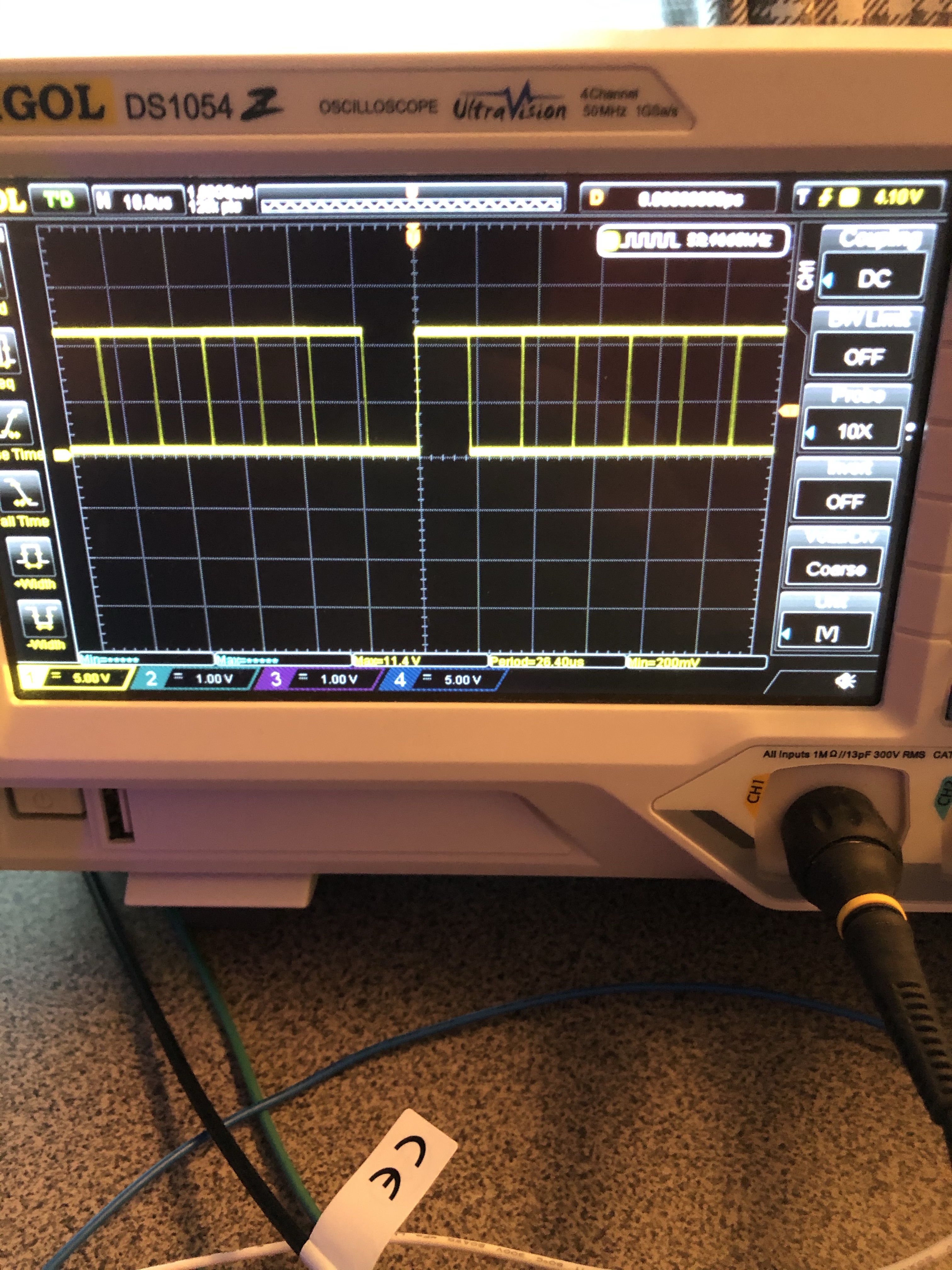
On this board – I used the diag ROM and was able to cycle through all the colors and measure the voltage outputs at the RGB connector on the board. I was using the DC voltage setting on my DMM and it was showing 7-9vdc. The monitor documentation specifies no more than 4v. I didn’t want to blow anything up on a G08. I spent a fair amount of time checking diodes, transistors, resistors around the outputs and they all seemed fine. Not having a G08 to test with had been adding a layer of complexity for this entire repair.
Finally I checked in with the Sega G80 Connection and was told to check the outputs using AC on the DMM. Perfect! Voltages are fine – I just measured them incorrectly. This board works as good as I can test on the bench. Cycling through the colors with the diag rom shows the appropriate voltage changes across the RGB pins.
X-Y Timing Board
I actually worked on this board last, it was a disaster. The hackery on the board was ugly. Board was labeled bad in 1982.. Has it really been sitting since then?
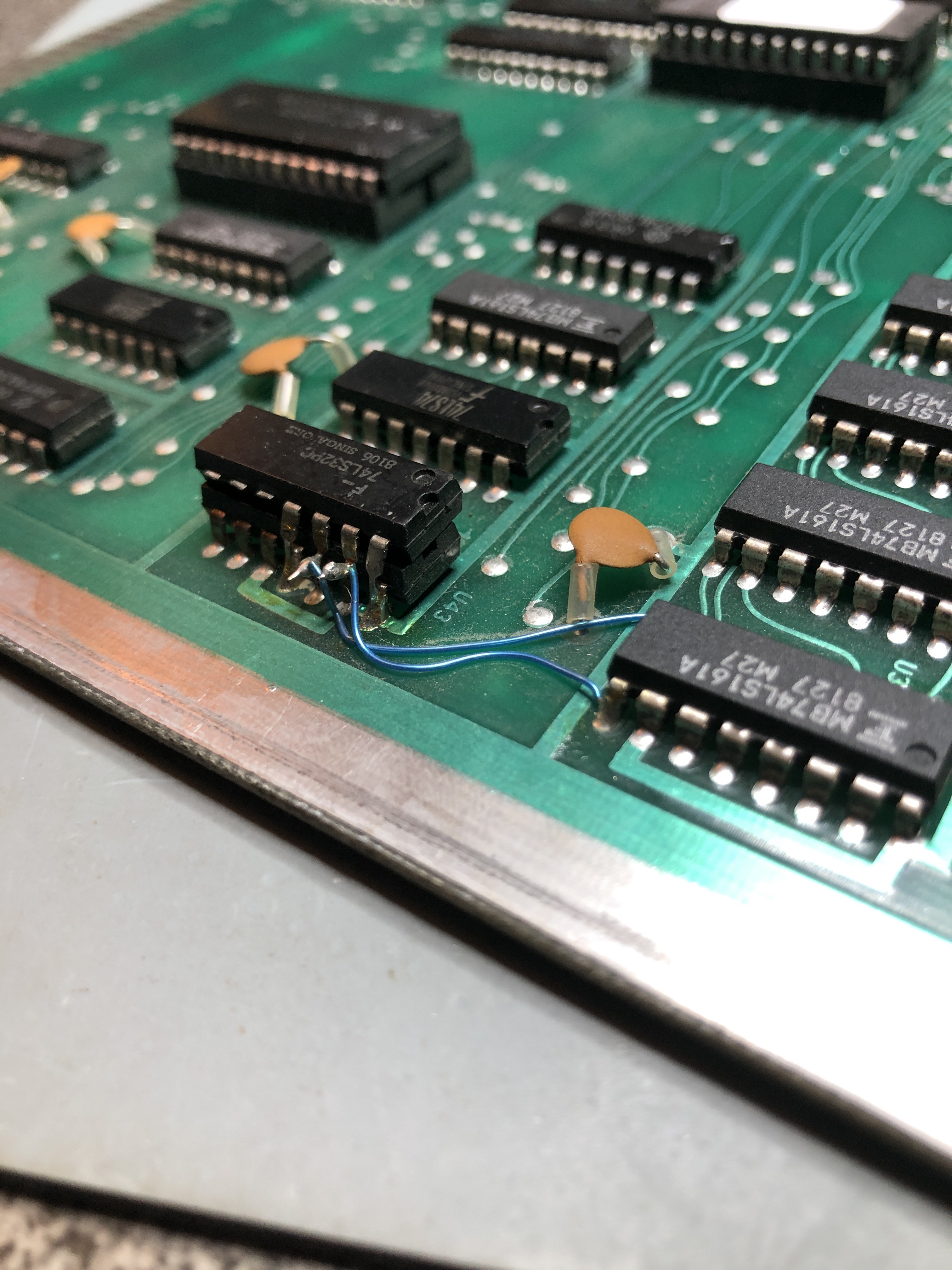

There were a few of these in this board. I documented them just in case any were valid and took all of this stuff off. The worst offender was the piggyback chip at U43. I pulled that out and replaced the LS74. Then beeped out each leg of the chip to see if it was connected to where it was supposed to go. Part of the hack was a cut trace on the backside.


Added a piece of Kynar wire and some solder mask. Fixed that hack.
Sega may have had these boards manufactured by different vendors. Between the good set and the eBay set – there were a couple of traces on this board (and the other) that did not exist. There were a couple of factory fixes. I only needed to add a wire between pin 1 and 8 on U14 to make up for a missing factory trace to get the board matching the schematic electrically at least.
Powered the stack up – but the game would not boot. I probed around with the scope and basically looked for signals into the board and off the board. This path lead me to U42 – a LS74. Good signals in and flatlines out. Replaced it and the game boots! On one of the other boards I had the same date coded LS74 that was bad. Two bad ones?
With the game booted, I had signals on X and nothing on Y.

These TL081’s were jammed into their sockets and working backward from the Y signal – its the first connection. Turns out they ruined the socket on the Y side for -12v input. I replaced both of the sockets and the TL081’s.
Once that was done the Y signal showed up on the scope, it revealed that only one half of the X signal was present. The signal didn’t go negative. Swapping the DACs made the problem move..
Solution: Replace bad X DAC – making progress! A screen full of vectors that are broken vs. a little line of junk that is broken.
A this point I had only found a couple bad LS74’s and the X/Y signals were a mess. I tested the LS74 at U25 and it also had good signals in and a missing one coming out.

With nearly no effort during removal – it crumbled. Big surprise. This was the third or fourth bad LS74 – I decided to remove all of them at this point. I pulled the LS74 next to it and it checked bad too. In total 5 of the 8 LS74’s in the stack (same manufacturer/date code: Fujitsu PCOM8048) were bad.
X-Y Timing board works!

The de-hacked and washed version of this board came out great. Looks like new. Just waiting on a few parts.
*** Burn in cycle ***
Once I received some new DAC’s – I went to test one in this board – out came the magic smoke, with just a hint of flame.
This time it wasn’t me! – I received a bad set of DAC’s. All from the same manufacturing lot. The vendor replaced my order and the new replacements are working great.
Speech Board
This was the second board I worked on and I was still getting a feel for how the stack worked at this point. It had a crazy failure. The stack would go through the sound test pattern and then hit the speech test pattern. Except it would play one phrase over and over like a broken record – “Damage repaired captain” – how fitting. Once in a while it would change phrases – but the board never got the signal to stop talking. I swapped all the socketed components from the good board and nothing changed.
Signals going into and out of the speech processor were consistent and there really isn’t much going on – on this board component wise. After poking around for a while on it – I put the logic comparator on the LS74 at U15 and it flagged a bad pin. Popped it out and it checked bad on the tester!
Replaced the LS74 – board fixed! – This was the first LS74 I had found bad – it was not yet a trend.

So now that I know that it was that chip…. The code/processor must signal on pins P17 and INT programmatically that the phrase is finished speaking. That gets fed into the LS74 telling the chip to stop talking on the T0 pin?. (this is my educated guess)
*** Burn in cycle ***
Has been working great all through the burn in cycle
Universal Sound Board
First board I tackled – Using the logic probe – poked around and nothing was happening on the CPU. Swapped the 8035 CPU from the good board – got all the sounds! After listening to all 28 sounds a few times, a handful of sounds were a little off.. All seemed to be explosion related. None of the explosions had life and a few of them sounded identical to each other. Which lead me to U60 – MM5837 – a noise generator chip.

Good noise signal from the good board on the left – flat line noise on the right. Part ordered – it’s not easy to get as it’s turning out. No US based vendors for it and I’m guessing it was not all that common. I had one Chinese vendor already cancel my order and the other is not responding after placing the order 5 days ago..
*** Burn in cycle ***
Added the noise chip
Sounds are much better than before. The noise signal has returned to this machine. After about an hour of use. The CPU died. This one was one of the replacements I picked up off eBay. Good thing I got more than one. Replaced it again and this one has been running fine for hours.
Prom Board
Pulled and tested all 23 EPROMS – 6 tested bad. Replaced all 6 and I was able to save the original stickers and reinstall.

Board Works!
*** Burn in cycle ***
No issues.

As it turns out – this Hallmark Ornament has been hanging in this window for the past couple of years. It’s just above my desk where I worked on the stacks. Fitting that they got fixed just below the Enterprise.
***** It’s been a while since I worked on Star Trek Stacks ***
I got one in to be looked over. The set worked fine.

The only thing wrong with it was some cold solder joints on the CPU board – No other issues.
Working on a set for a Friend:
CPU board: All 4 RAM were bad
Sound Board: All the ‘Blue’ sounds were missing.
Poked around a little bit until I found the dead outputs. Replacing CD4053@U31 restored all of the Blue channel sounds. Makes perfect sense, it is the analog switch right before the sound outputs.
XY Control board #1:
Looked great on the scope. Ran with a G08 monitor displayed no colors.

Transistor cold solder joint basically shut off the XY Colors. Q1 acts as a switch for 12v+ pullup for the color outputs.
It also looked like it had a bad RAM, but found a weakling chip that was corrupting data just a little bit. Replacing LS374@U13 cleared it up.
Board works!
XY Control board #2:
Replaced a bad RAM – board works!
While I had my test rig out…
My personal sound board developed a bad explosion sound a while back. I tracked it down to noise generation on the ‘Green’ sound channel. Unfortunately the source of the issue did not readily present itself as a dead output. I socketed and ‘put back’ a few chips in this circuit until the culprit revealed itself.. CD4053@U15 had not failed, but it was pulling the noise output negative and causing the issue.
Board works!
One last XY control board for a friend..
This one has been problematic for a while. There is one remaining graphics glitch, however I found a great example of a thermal failure.
When cold, the vectors are all messed up. As the board warms up, they clear.
Watch the heat gun clear the vectors and the freeze spray mess them up again.
