

My first full bench harness was for Battlezone since I do not own one. I knew when I made it that it would not be very well designed or efficient. I’ve also been repairing boards all curled up behind my cabs (Asteroids comes to mind..) and after making a slightly better DigDug bench harness, I didn’t want to make more one-off harnesses for Tempest, Star Wars, Asteroids and a bunch of others. I came up with my version of a universal Atari bench power harness. I’ve done a few with Jamma adapters on the bench, but they do not always supply the same voltages as the originals.
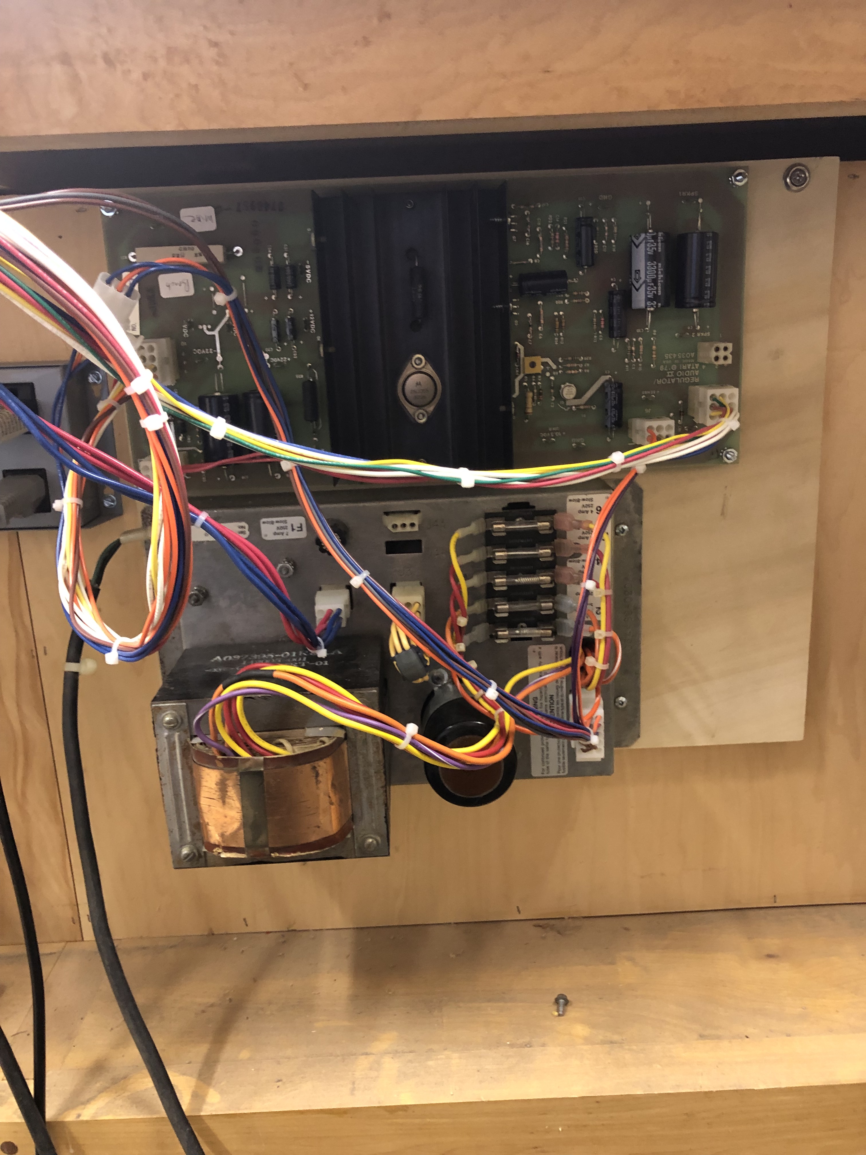
First step was to mount the Power brick and ARII onto a backer board and get power to the ARII. I have two of these setups now – one raster – one vector.
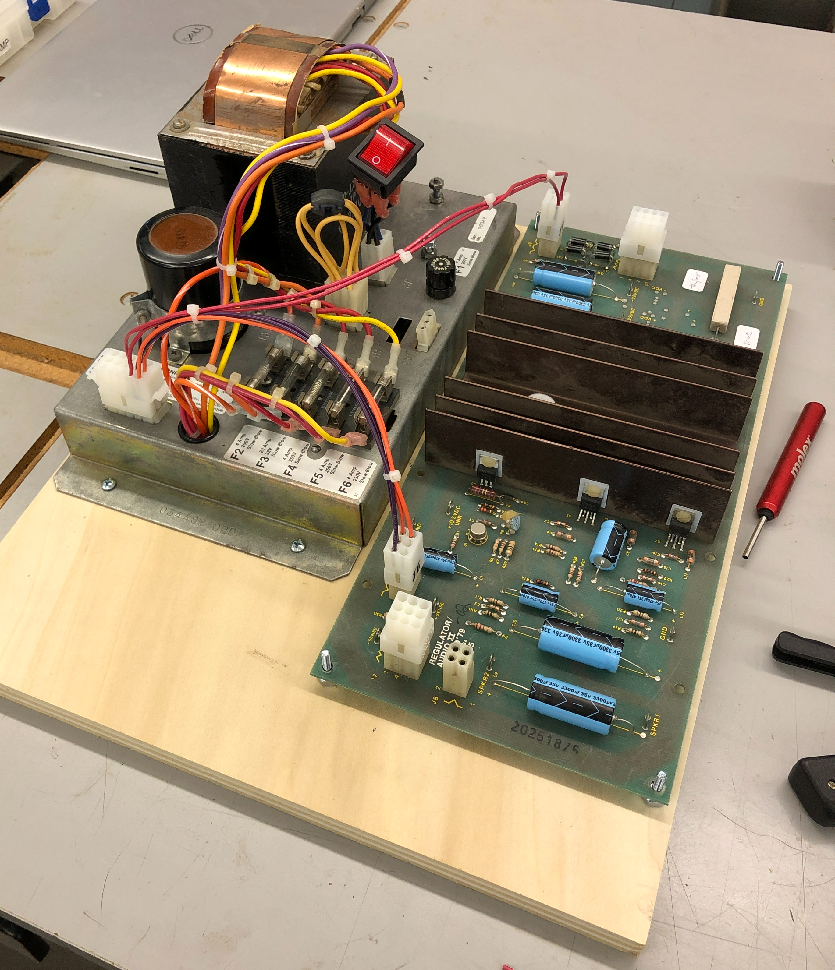
All of 6 wires get power off the brick and onto the ARII via J6 and J9. I also raised the ARII up off the backer with spacers to provide heat dissipation clearance.

Here is the completed Brick to ARII cable. This one is for vector bricks. I made another for raster bricks which is pretty much identical except for a couple pins. Along with J6 and J9 there is a connector for monitor power and the second one for 6.3VAC and 10.6VDC. Those voltages come off the brick and get used at the board level sometimes.
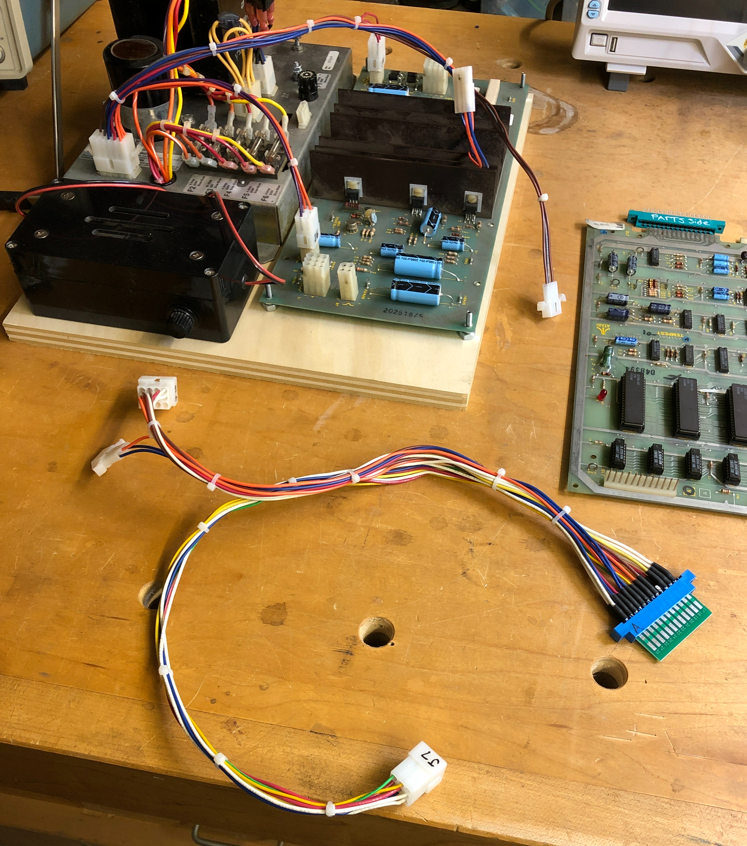
My “Universal” adapter puts all of the Atari voltages onto a 24P edge connector – shown here with a cut Jamma finger board. It connects to J7 and J10 and to the 6.3VAC/10.6VDC connector from the brick harness.

It picks up all the voltages and provides many ground connections and mimics how Atari uses these power lines. I matched many of the Atari colors and made a few up when I needed too.
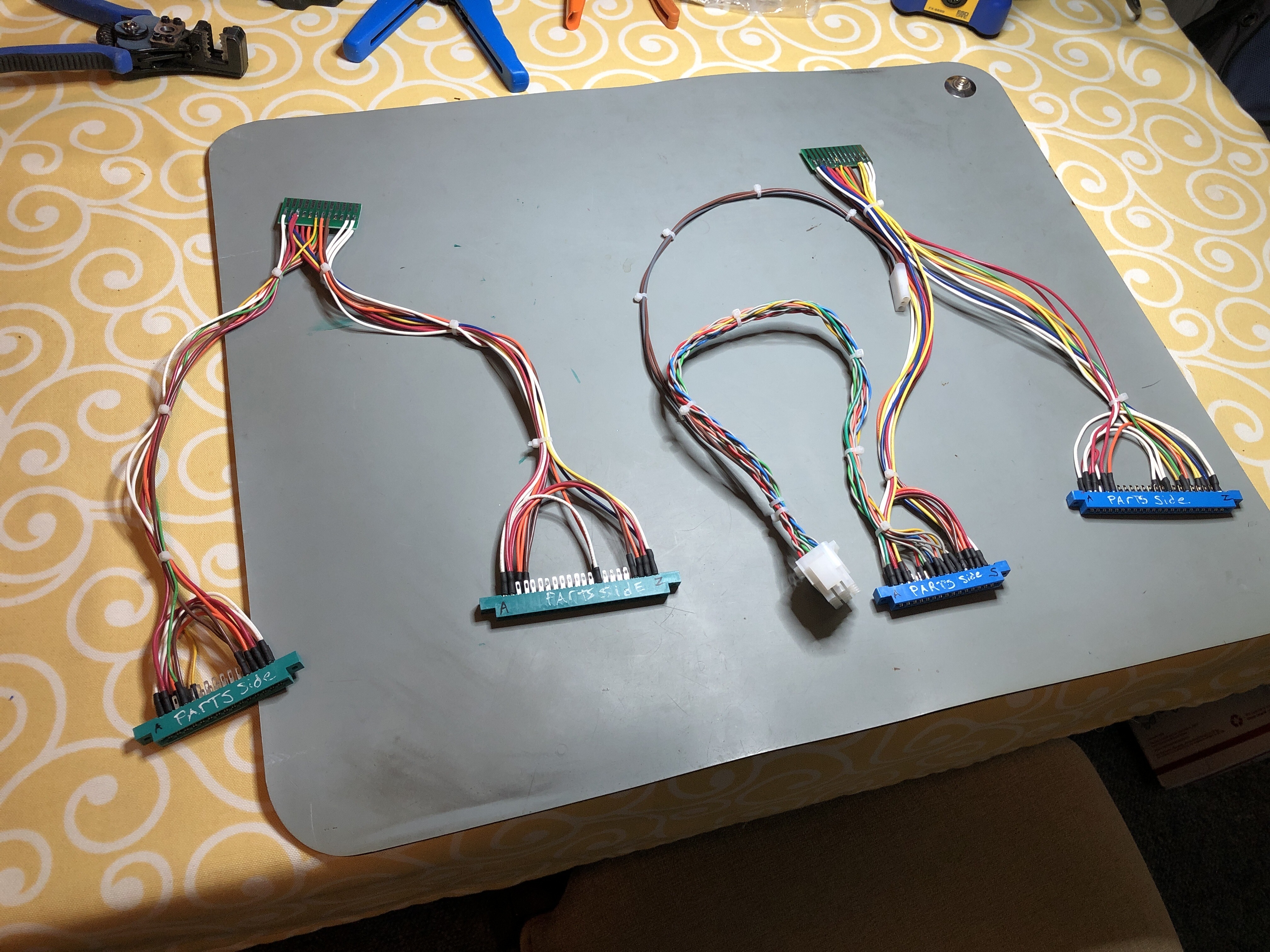
My first two new adapters. Tempest on the left and Star Wars on the right. These are so much cleaner than the old way. I started with just the power wires on both and went back later to add video connectors. I’ll add control connections at some point. Instead of making each harness with a long video cable, I went with a short one. If the monitor is on the bench it will reach.. But if needed…


I made a 4′ long video extension cable. The originals had twisted wire. It’s supposed to cancel electrical noise from other wires. Using the drill to twist them was a good find on YouTube. Monitor cable extender works great.

I went back and stripped off all of the extra connectors and reworked my original Battlezone harness to the new setup. Much easier to work with it now.

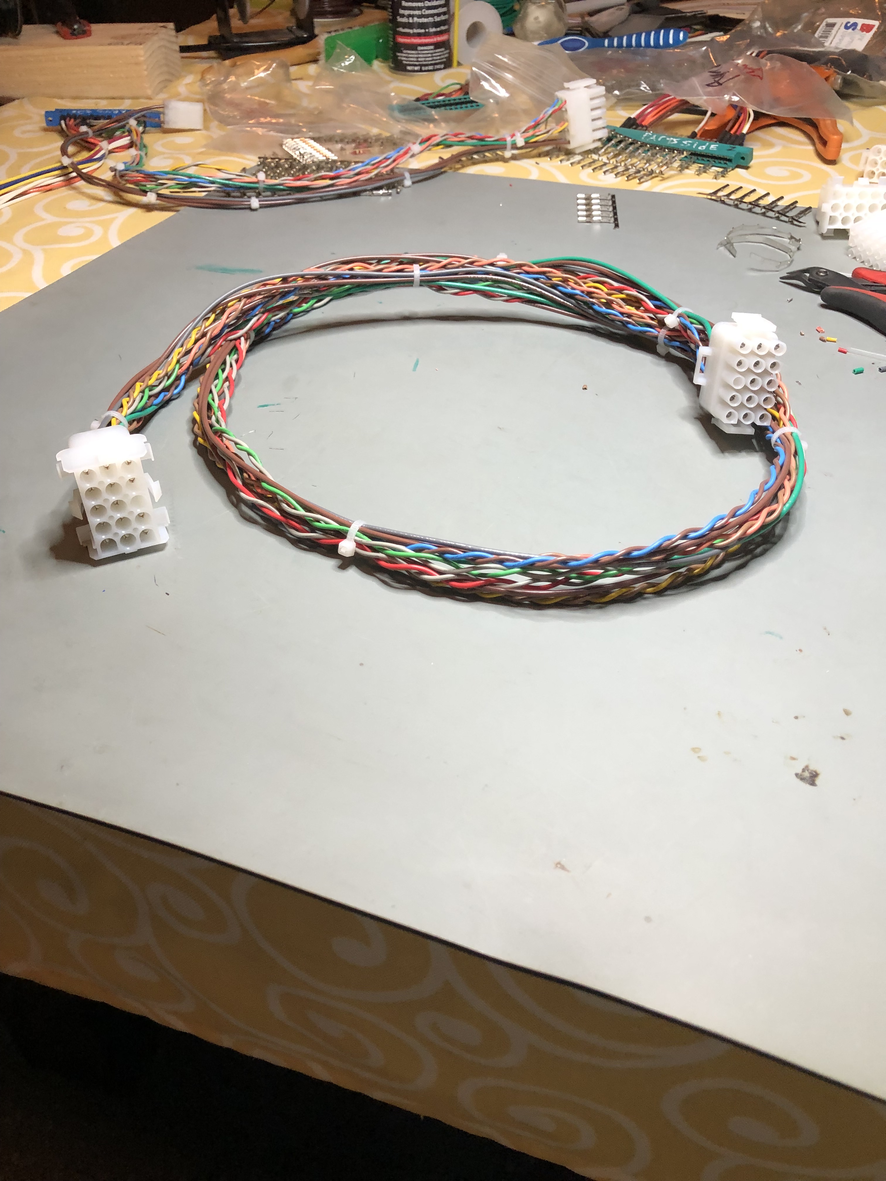
Tempest adapter with a long bench interconnect cable I made up.
The final part was I had to cut up Jamma finger boards to make adapters and I was doing a lot of counting and cross checking of wiring during fabrication.


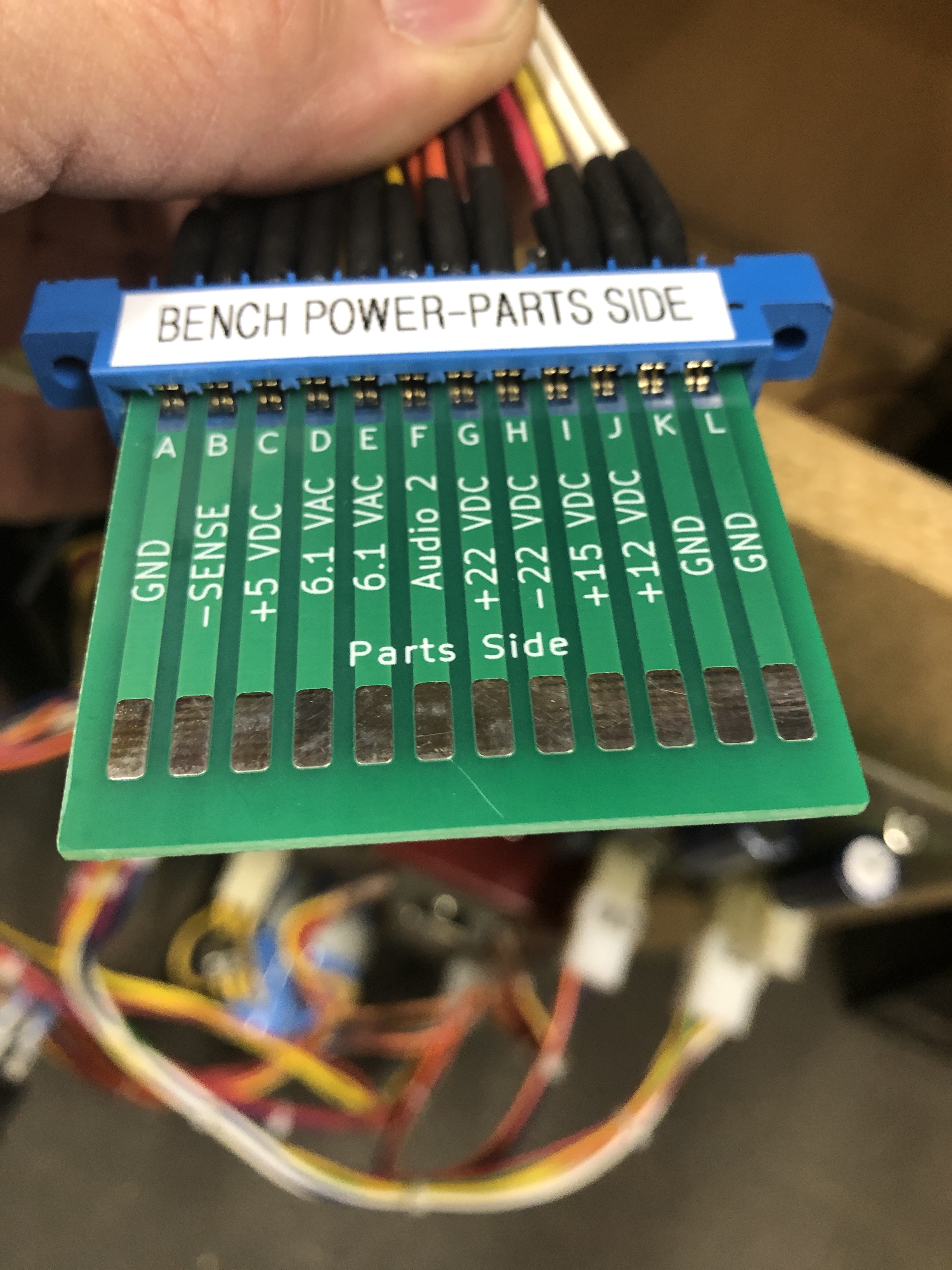
I drew this up in KiCad and had 30 made. Pretty sure they cost less than the Jamma adapters I was cutting up. I’m going to go back and rework my other harnesses with these. Going forward it makes each new harness simpler. BTW: 9MM tape is the perfect width for the label maker for the edge connectors.
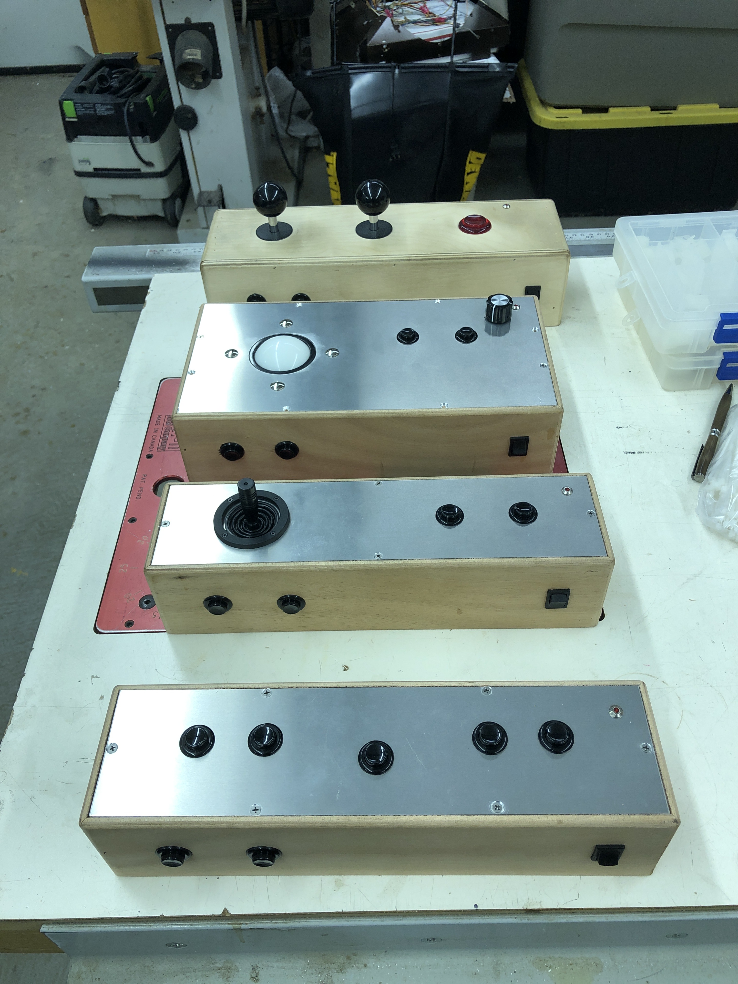
My first bench controller was the 2 stick one at the top. I made up some additional ones to cover the vast majority of inputs.
- Trackball controller can handle Trackball, spinner and most optical input games.
- Single stick controller is analog – Now I can bench test Star Wars, Red Baron, Food Fight, etc.
- Button controller is for games that are all buttons – Asteroids, Gravitar, etc.
All have coin, start, test button, Coin LED (used to check for resets) as well as others.
*** Updated ***
I’ve added a little more to make life easier.

After using just the adapter connected directly to the power supply through an edge connector – it was flopping around the bench and I was always wanting reference voltages. I designed this (blue) PCB with test points for ground, 5V+ and 10.6V+. I also added a volt meter on the sense lines to see the voltage at the board level.
The ground points came in handy for connecting the scope without wires all over the place. When I test coin counter and lockout transistors – I need the 10.6V to mimic the actual game. The whole assembly mounted to the bench is just an added bonus.
The vector power supply is out of the way on the back of the bench.
Because it was all easy to do – I made a portable one so I can use additional table space when needed.
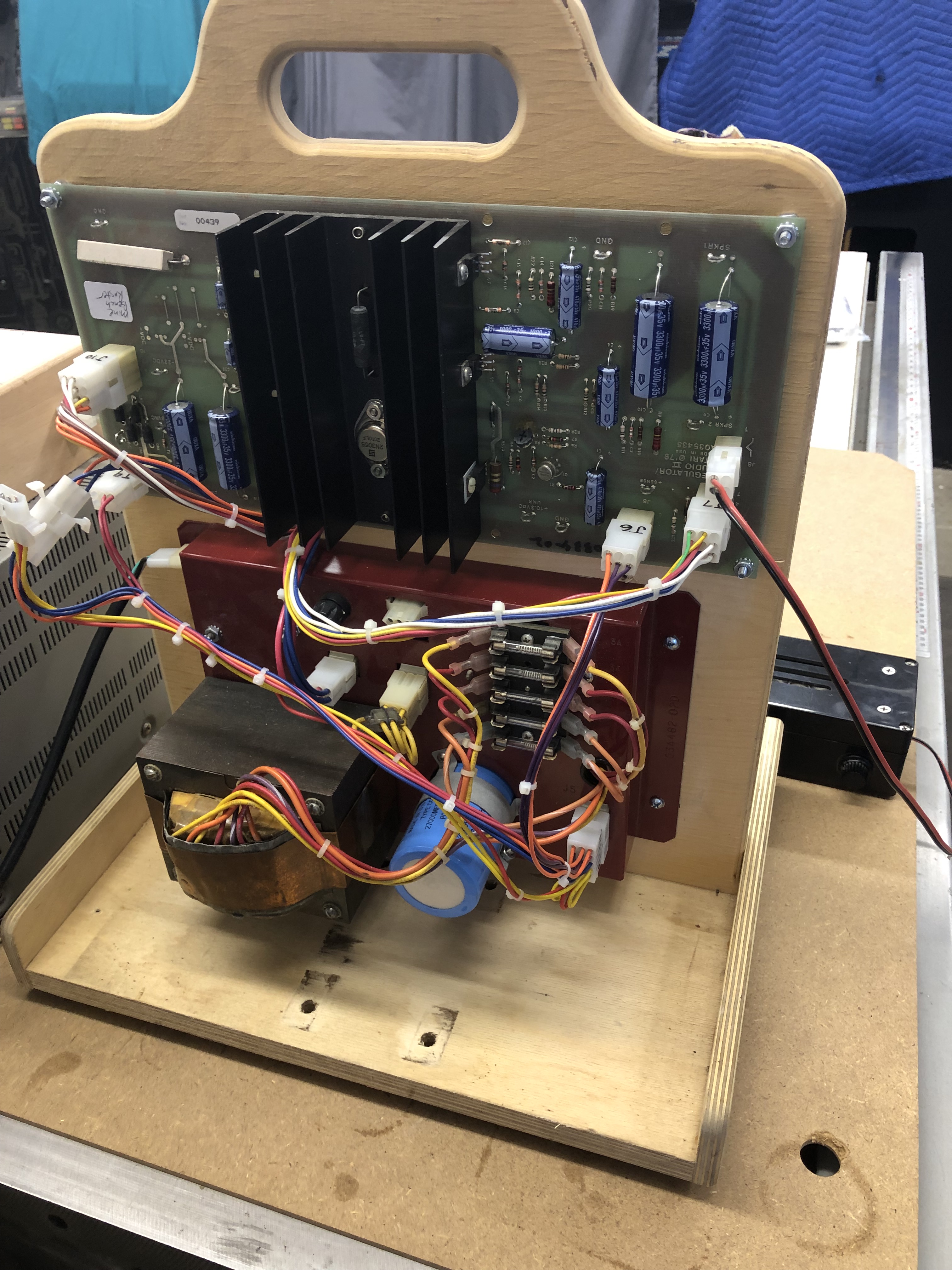

Complete with meter and adapter.
Been a while since I’ve updated this post – as for bench adapters – I have over 30 of them at this point. They are a true time saver and worth the 2-3 hours of assembly time.
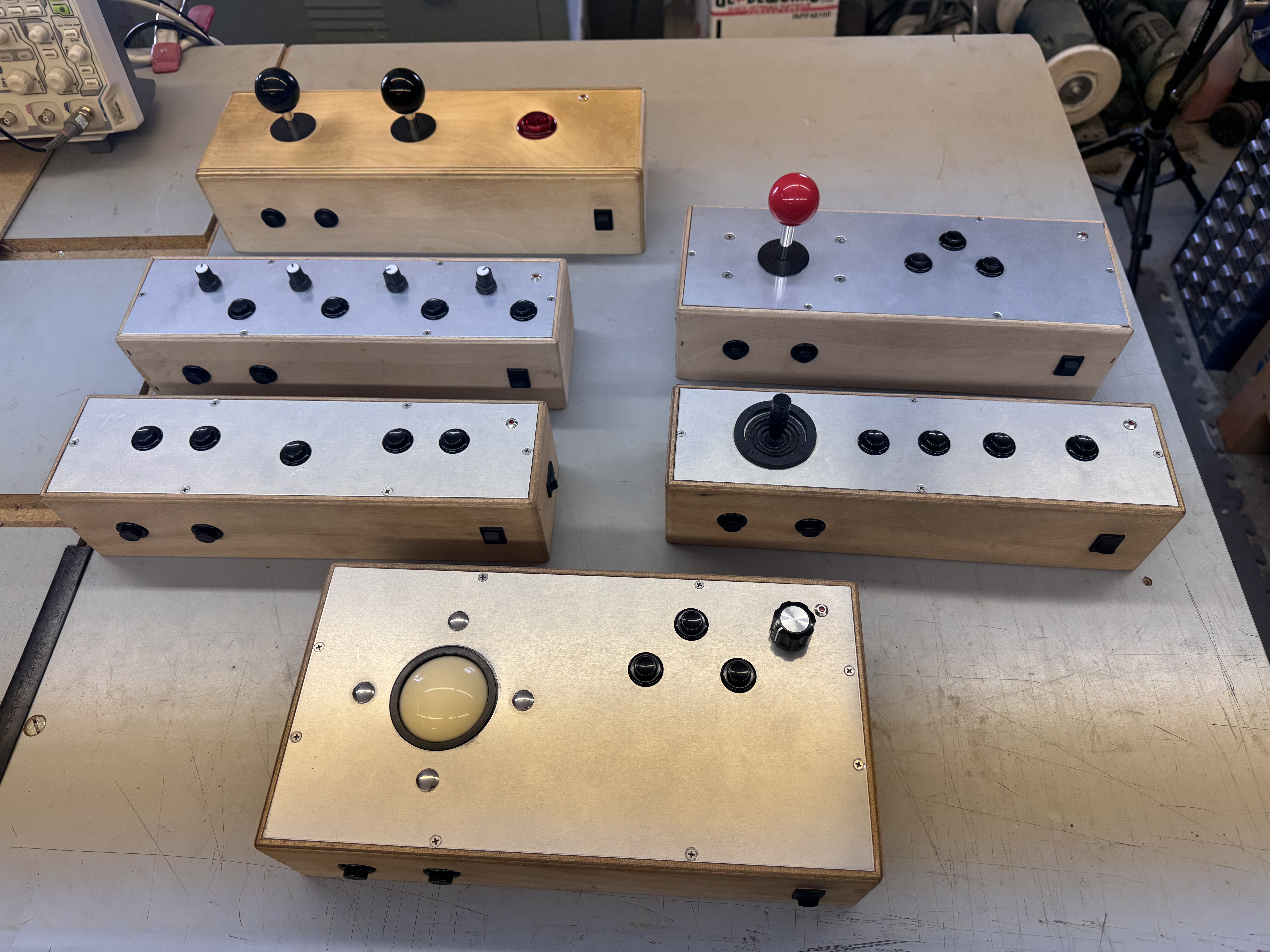
My collection of controllers has expanded too.. Dual stick was originally for Battlezone and the first one I had made. All share a lot of common buttons – which share the same pins on the connector. The unique controls are different pins by controller. They all have a start, coin, test, slam button and an LED to match the coin LEDs on many games.
The controller list with some of the games supported by controller..
- Battlezone – dual joystick
- Warlords – 4 pots to test gameplay with 4 start buttons
- This is a bit of a single use controller, but I’ve repaired a number of Warlords now
- Buttons – Asteroids, Asteroids deluxe – button based games
- Trackball – Because it is optical – I can use this for many games
- Centipede, Missile Command
- Tempest – yes! For bench testing works perfect. The Tempest knob is a optical rotary controller.
- Pole Position – Same as above. On the bench – works great. The knob on the upper right is the gas pedal and on the right side there is a shift button.
- Single (Jamma) Joystick – I use this for Jamma game testing
- Needed more buttons than I could add to the double stick
- Analog Joystick – Used for Foodfight, Red Baron, Star Wars and I,Robot
- This one has some special features – rocker switches so I can reverse the direction/polarity of the stick – the games are different directionally sometimes.
- The original sticks use 5K pots, but they are often mechanically limited in range so the voltages often go from 1.5v-3.5v vs. 0v – 5v. I recently added voltage dividers so that I can have better adjustability based on the game.
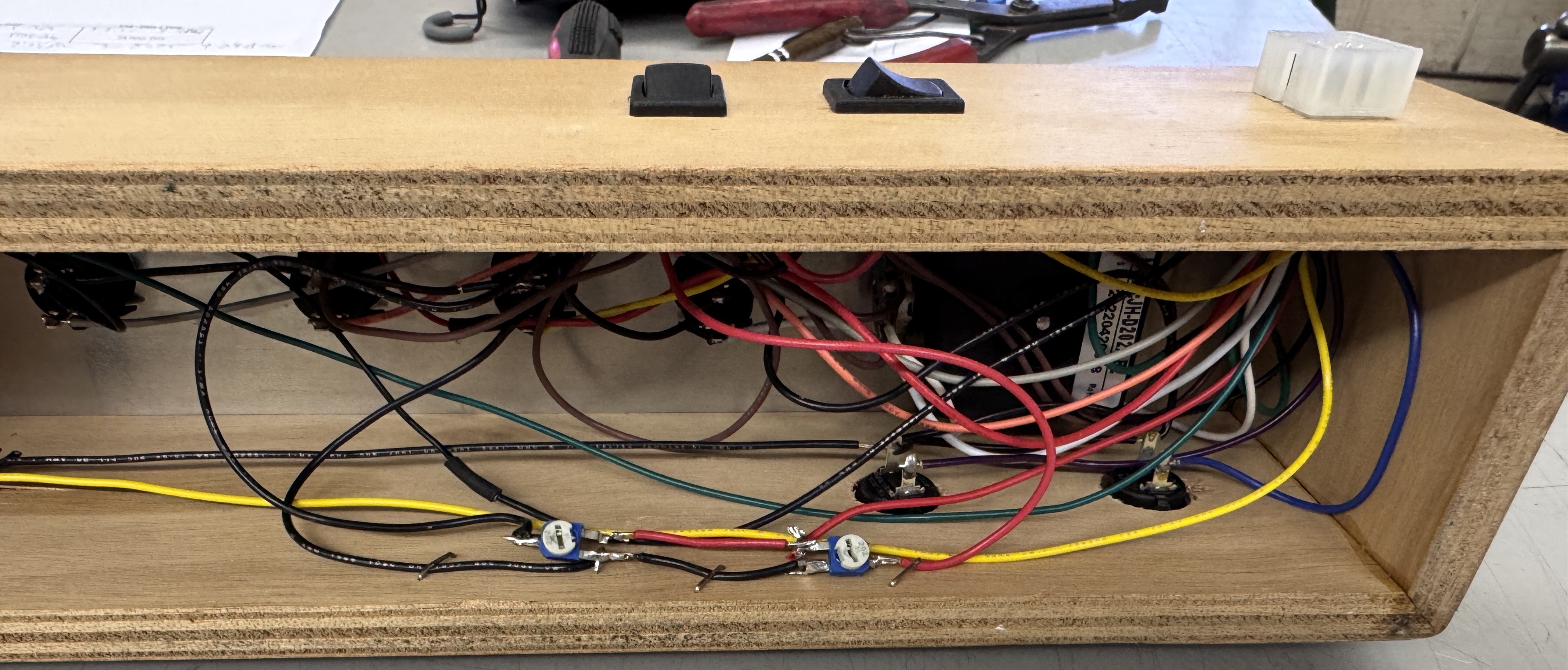
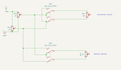
Between the ability to reverse the stick and the voltage dividers, it was a bit to keep track of.. I had to draw it all out so it made sense.. You can see the reversing rocker switches on the back of the controller.

Before adding the voltage dividers, the stick had ~3/8″ of throw before it went outside the box on I,Robot. Ok for testing sort of.. But I actually wanted to play a bit and the controller was way to sensitive. Now I can have full throw and keep adjusted in range..
**** New addition ****

When testing a repaired board.. The first 12 hours I burn it in and see what/if anything fails or it resets. My second test cycle is more of a try to break it test. It is done by a smart home automation. Power on for 30 min, power off for 60 min. 16 times (24 hour test cycle). I’m not looking to see if it fails during the test – I just want to see if it gets to the other side of it and works. Once issue I have on occasion is that both of my work stations are running 24 hour tests and I have no place to go.. So I made a third test station. I had the parts and it went relatively quick. Fits up on a shelf and I keep the test queue moving..

[…] Atari Bench Power Test Rig […]
[…] Atari Bench Power Test Rig […]
[…] Atari Bench Power Test Rig […]
[…] Atari Bench Power Test Rig […]
[…] Atari Bench Power Test Rig […]
[…] Atari Bench Power Test Rig […]
[…] Atari Bench Power Test Rig […]
[…] Atari Bench Power Test Rig […]
[…] Atari Bench Power Test Rig […]
[…] Atari Bench Power Test Rig […]
[…] Atari Bench Power Test Rig […]