
Received a request for an I,Robot repair from someone I had done some work for in the past. On a board I’ve never worked on before – I like to have at least one other PCB as a reference, working or not. That way I can go back and forth and eventually get both working as I learn how the board works. Fortunately I also had a couple of friends who wanted me to look at their I,Robot board sets so I got to figure these out with 3 sets of boards! (to start)
But first – I have to build a bench adapter..
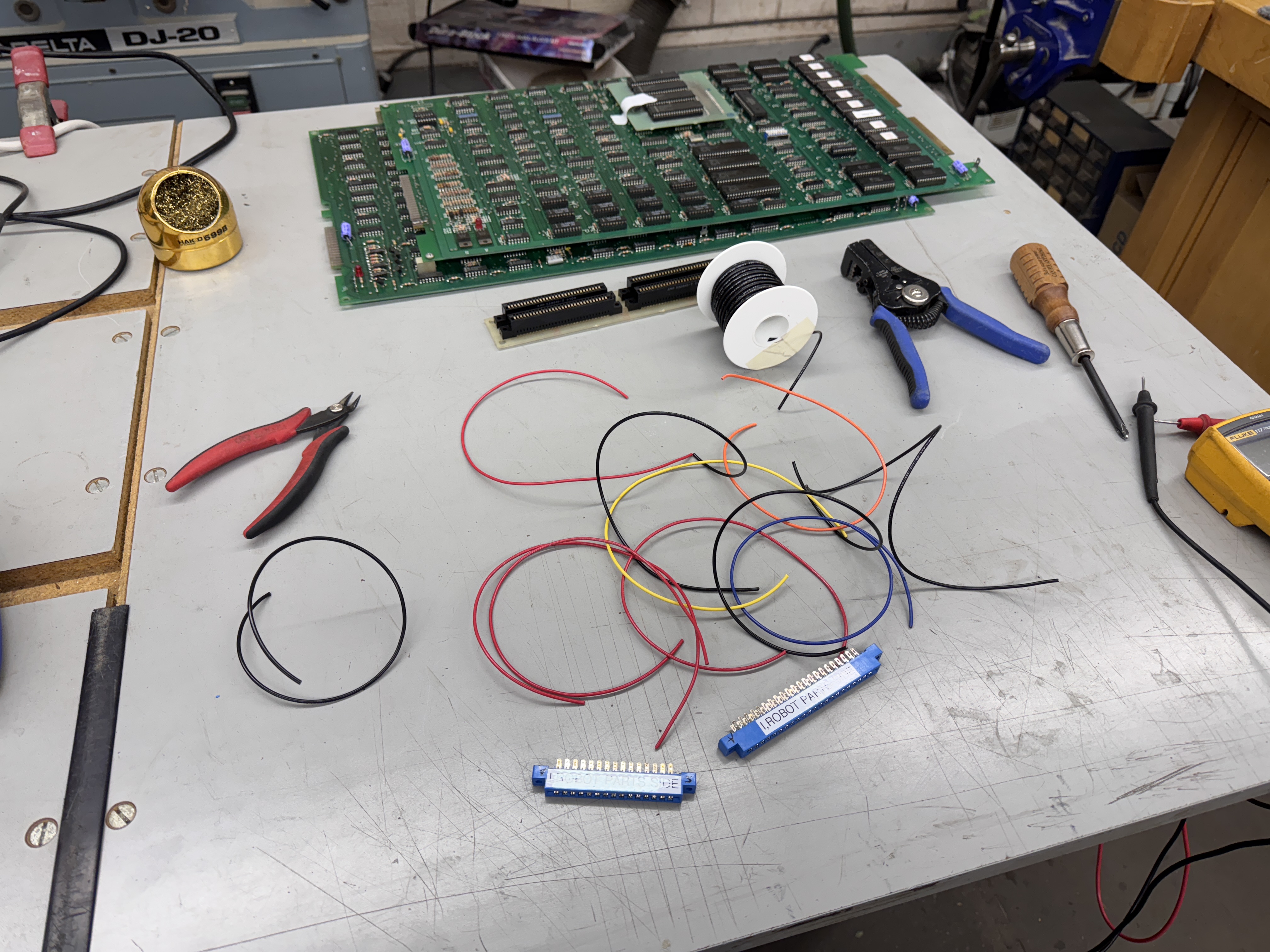
I, Robot is a 2 PCB stack and came originally with a 10A switching power supply. My bench setups are ARII based (5A) – so I add in a bench power supply when necessary. I use the same configuration for Pole Position which uses 2xARII’s. All of this is so I can utilize my Bench Power Test Rig.

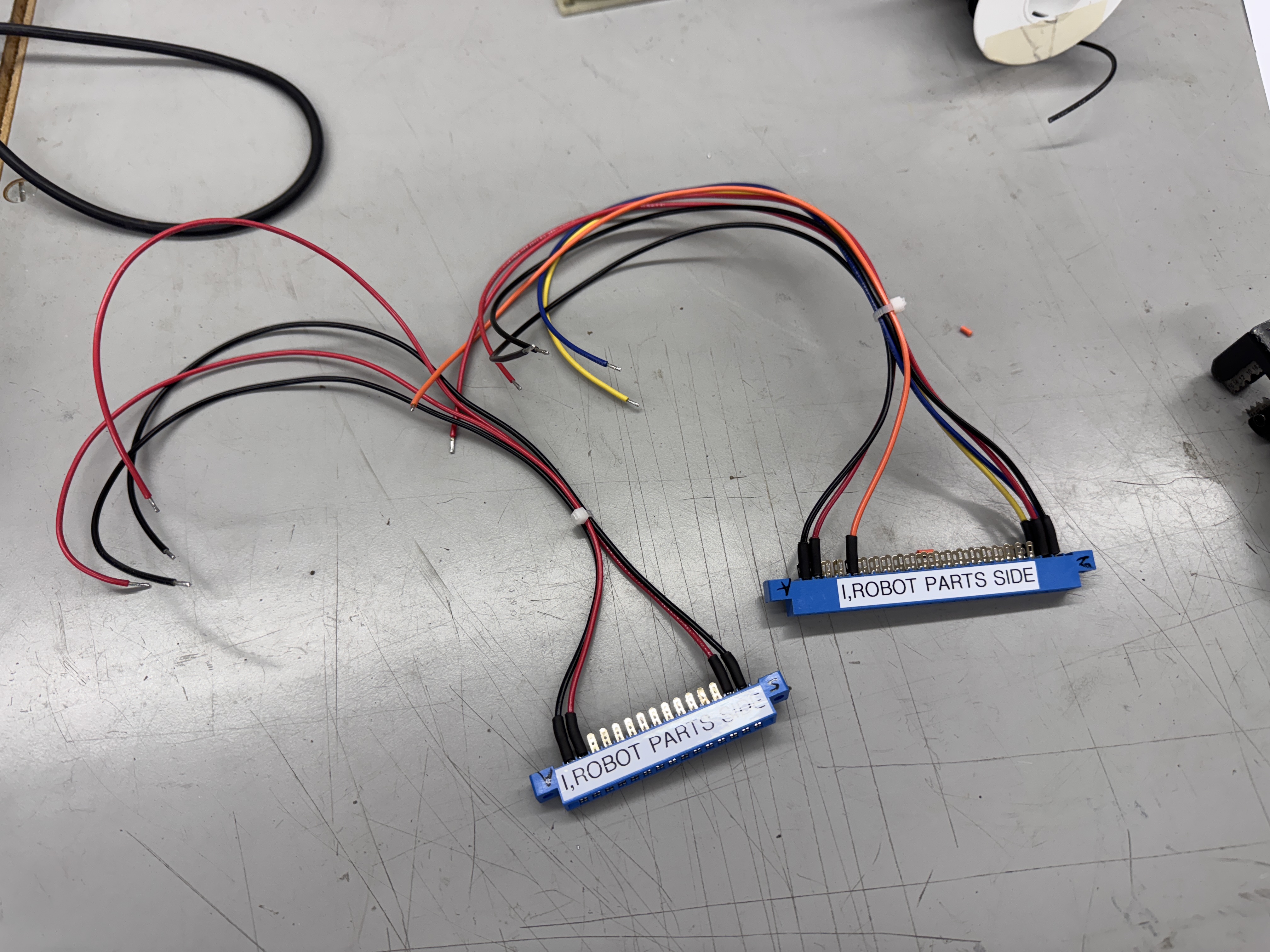
Here is the completed harness adapter. The CPU board is connected to my bench rig and the Video board is connected to my bench supply. I’ve have this setup pretty standardized and can change boards very quickly. This one took a little work to get going.. I had initially tried to just use the ARII w/o the bench supply – no way.. Also the schematics conflict on a 15.5V/10.3V line going in to the reset circuit. I initially used the 10.3V off the ARII (which is unregulated) and the boards would randomly reset, but many Atari boards use this voltage as part of the reset circuit.. I moved it over to the 12V regulated voltage from the ARII and no more resets. Good to know..
Board #1 – In for repair
This one came in with reported memory errors. The owner had tested all of the RAM with the Inquisitor and could not find issues.


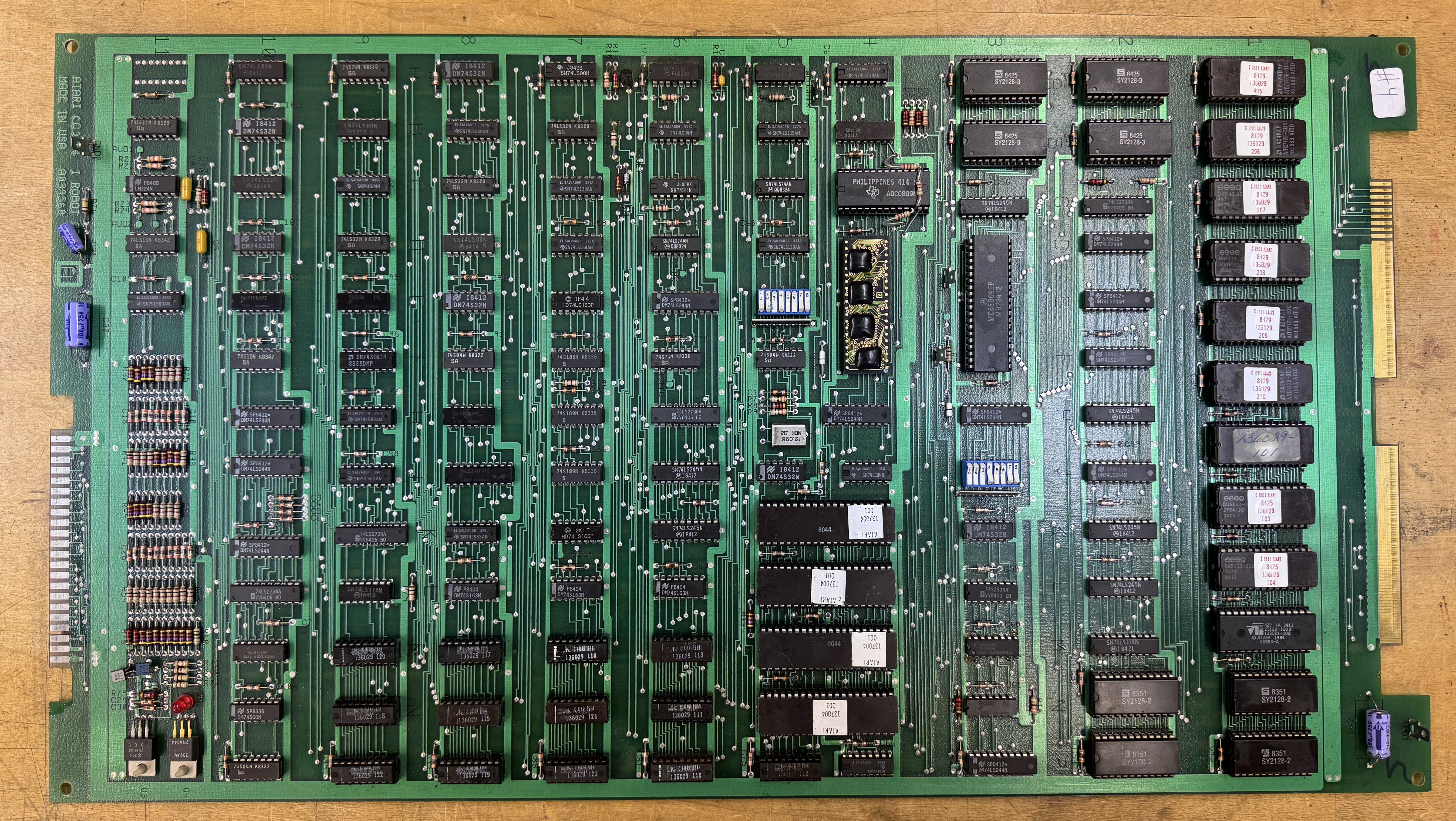
Here is what an I,Robot sets look like. Lots of chips and power hungry like Pole Position sets. This particular quad Pokey eliminator is a bit misleading. If you zoom in, it has Pin 1 marked at the wrong end of the footprint for connecting to the board. There is a little ‘1’ in blue marker showing the actual Pin 1. I did a bit of verifying here just to be sure.
First up was the edge connector:

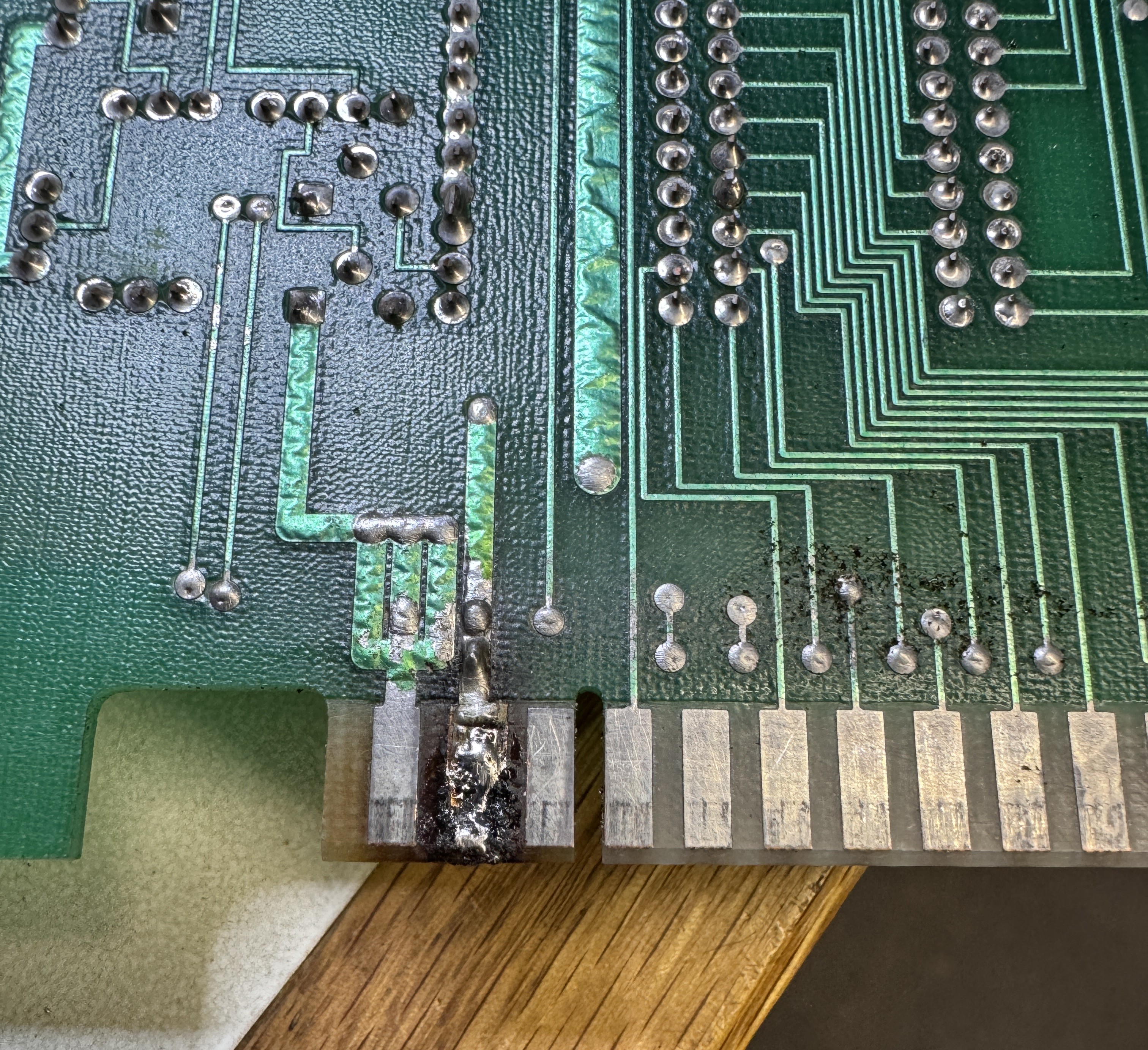
This needed to be repaired.. I removed the bad solder and cleaned up the finger area with alcohol. There was a small divot that I filled with UV Cured resin and then I flattened the area. Final steps..

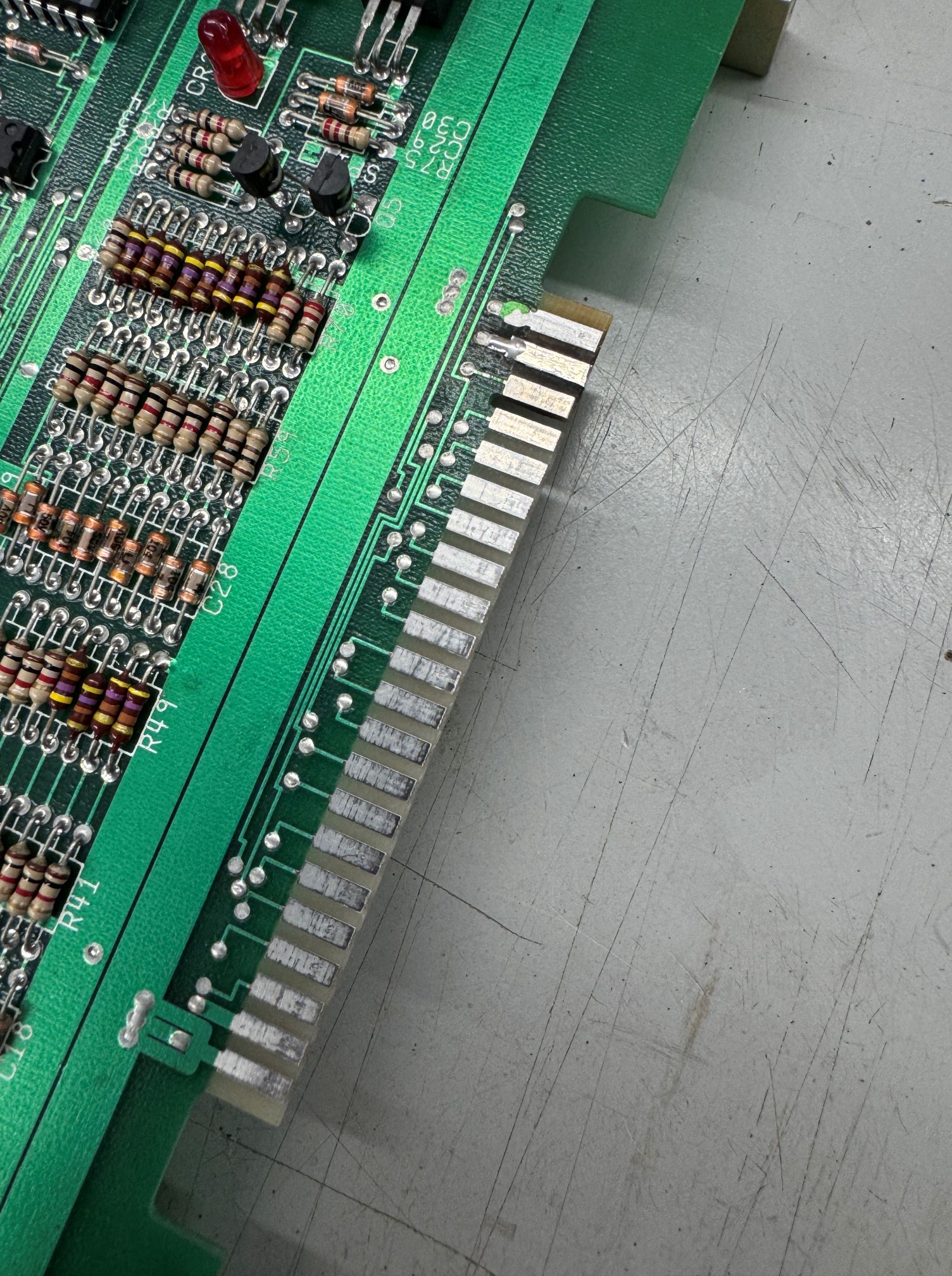

Replaced the copper foil and coated with liquid tin to protect against oxidization. Now that I can connect to the PCB without issues. I also performed all of the chip cleaning, etc.. Many socketed chips!
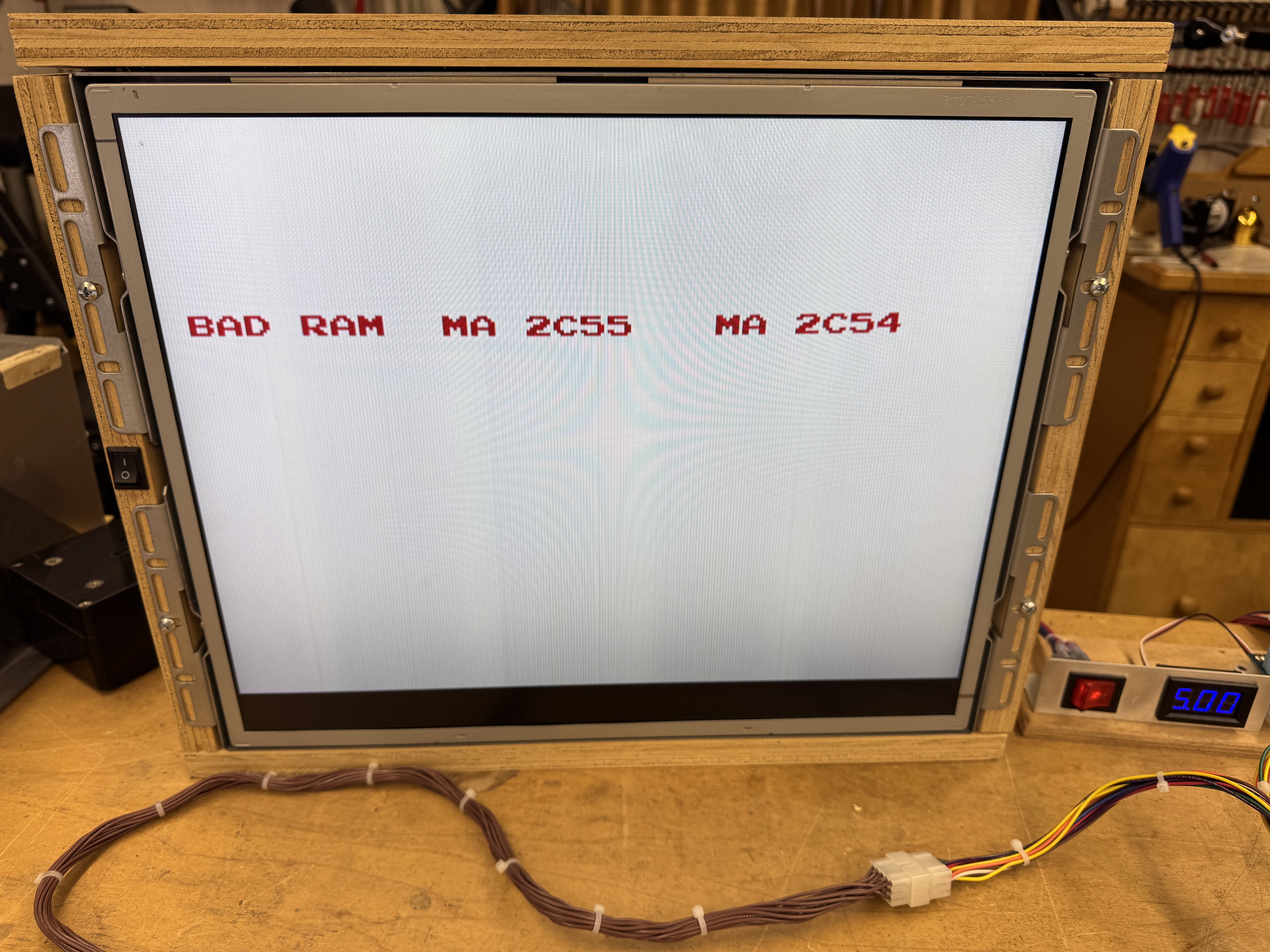
First error – BAD RAM W2. The self testing in I,Robot is pretty advanced. Star Wars was the most advanced to this point for me, and this is a bit better than that. The manual showed it could be RAM 2A, 2B, 3A, 3B. Swapping them around did nothing.. A close inspection showed that the socket @3A had a questionable pin. Replacing the socket fixed this memory error. Off to a good start! During some of the ‘figuring out’ of I,Robot I was swapping boards around from the 3 sets to determine if any pairs of boards worked together. At this point I had one of the other Video boards paired up to the CPU board. Once this error was cleared
This error was pointing to RAM on the video board. I swapped on one of the other CPU boards and got this.
Great! The video board from this set was working. It has a graphics glitch, but the RAM error from above was from the CPU board side even though it was pointing the Video board. This glitch looked like RAM and it was..

Here is the video RAM section – probing these showed RAM@11L and RAM@12K were bad. Replacing them got the video board 100%. Now back to the CPU board..
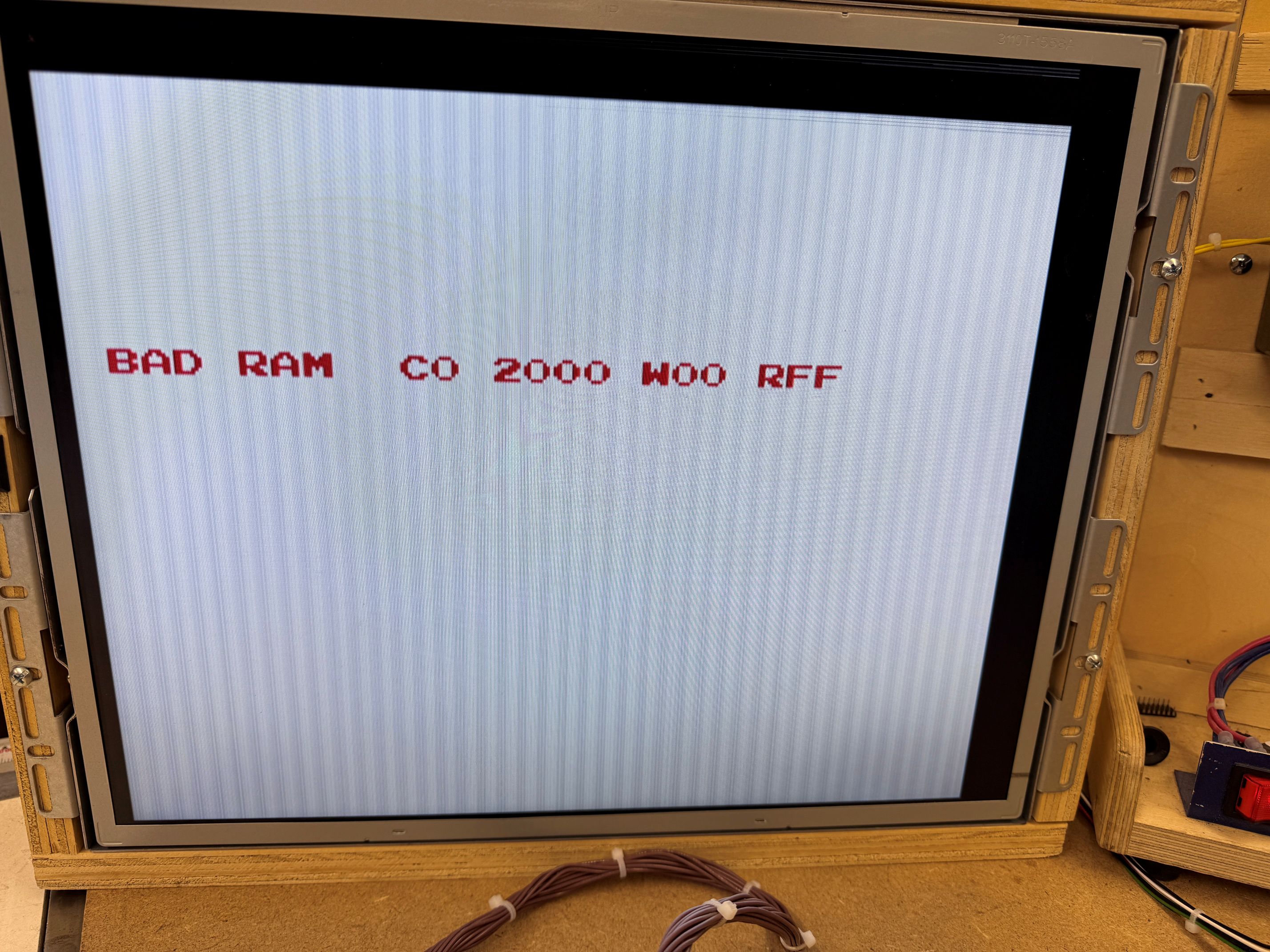
The final error was not RAM on the video board – but testing with a good CPU board showed that the RAM (C0) that it was flagging is the very first RAM it tests on the video board. I verified by removing that RAM from a working video board @1C and reproduced this error. My issue is the CPU board not talking to the video board. At this point I spent a fair amount of time probing the CPU board looking for the cause, but starting at the Video board since I knew exactly the RAM it wanted to talk too..

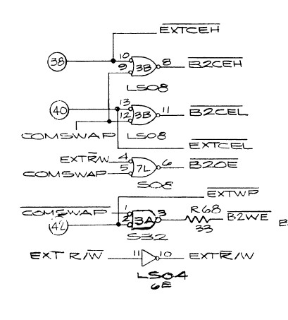
the RAM@1C was not getting selected /BICEH@pin18. That signal originates at LS08@3B Pin6. It took a while to trace it all around, but /EXTCEH@3B was not signaling.. Here that backtracks to PIN38 on the interconnect back to the CPU board. I chased a few ghosts during this discovery phase too.

The names are a little off between the sheets, but this signal connects to Pin37 on the interconnect. Going backwards through the LS08@10C and then to LS32@11B… The LS32@11B was bad. Replacing this restored communications to the video board! The RAM sockets on the video board were also a bit suspect, I replaced them to eliminate any other odd graphics issues.
Board works!
Board #2 – In for repair – friend’s board that had issues.
Sets #2 and #3 came over as 4 loose boards. I paired them up in no particular order. None are marked with serial numbers as Atari often did.

Here is the CPU board with an original quad Pokey. Atari did a better job on the ground connections on the edge back plane edge connector vs. some of their earlier designs.
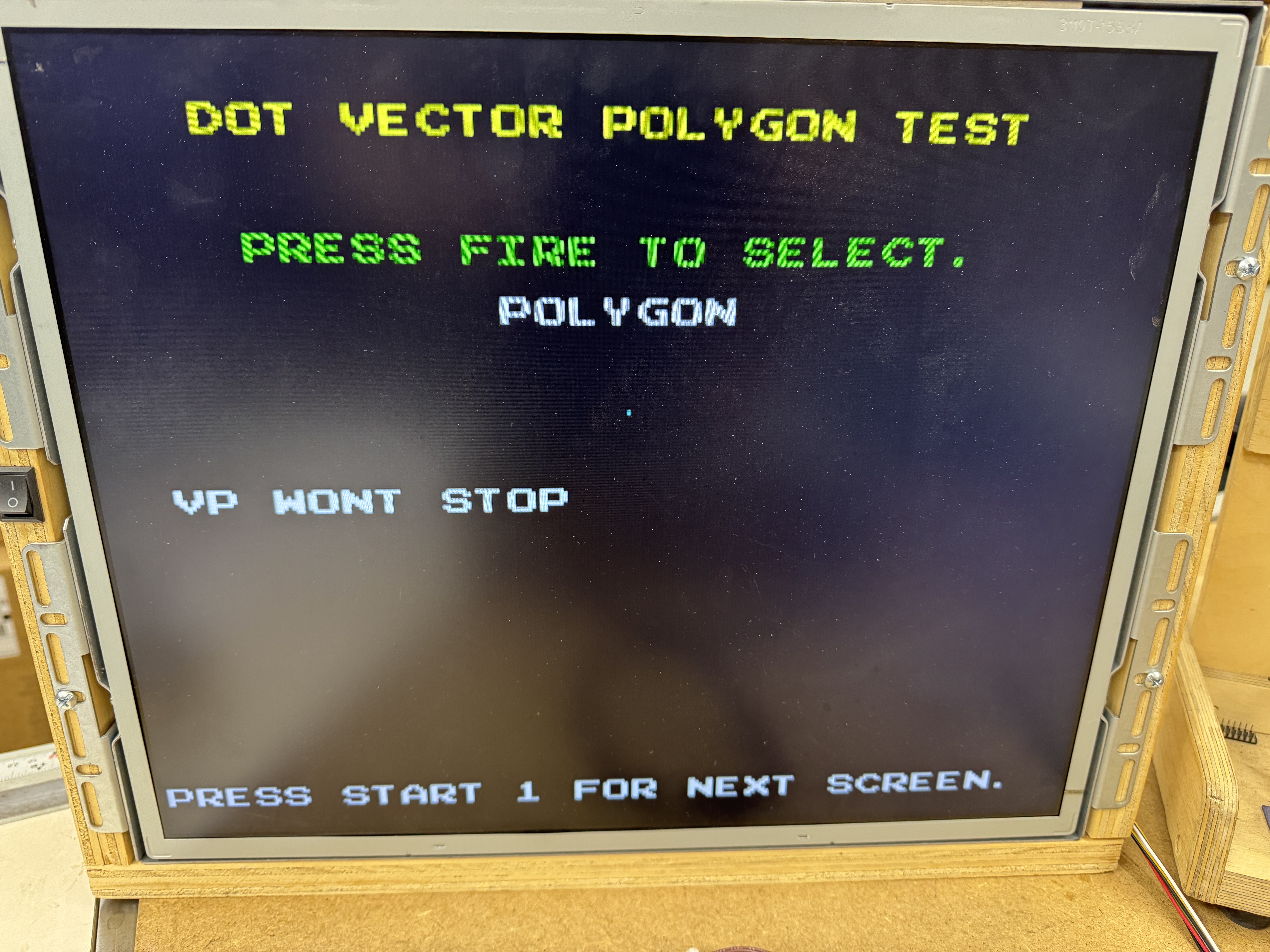
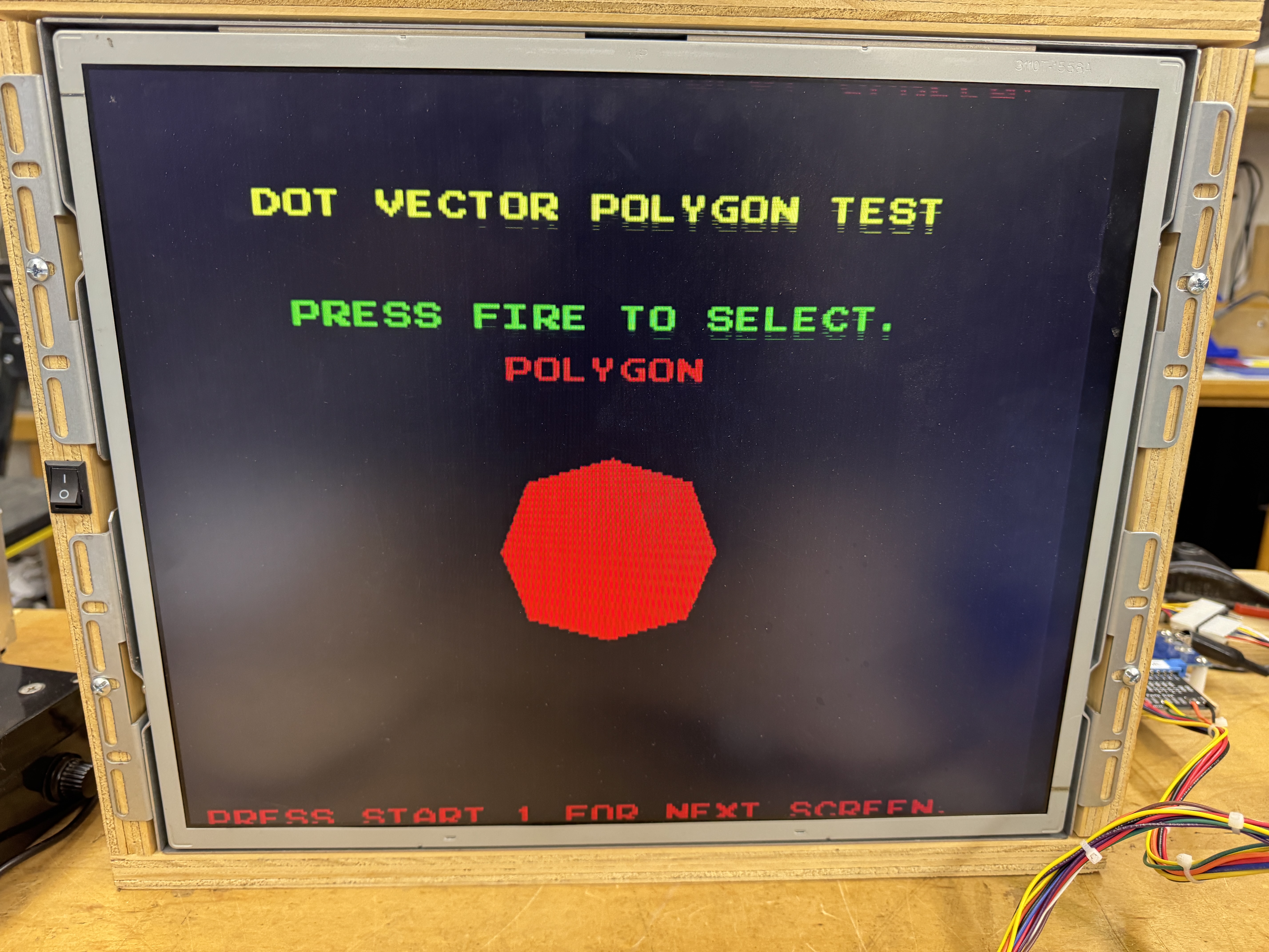
Here under the word POLYGON is a single dot.. It should be an actual POLYGON as on the right. Very Missile Command…
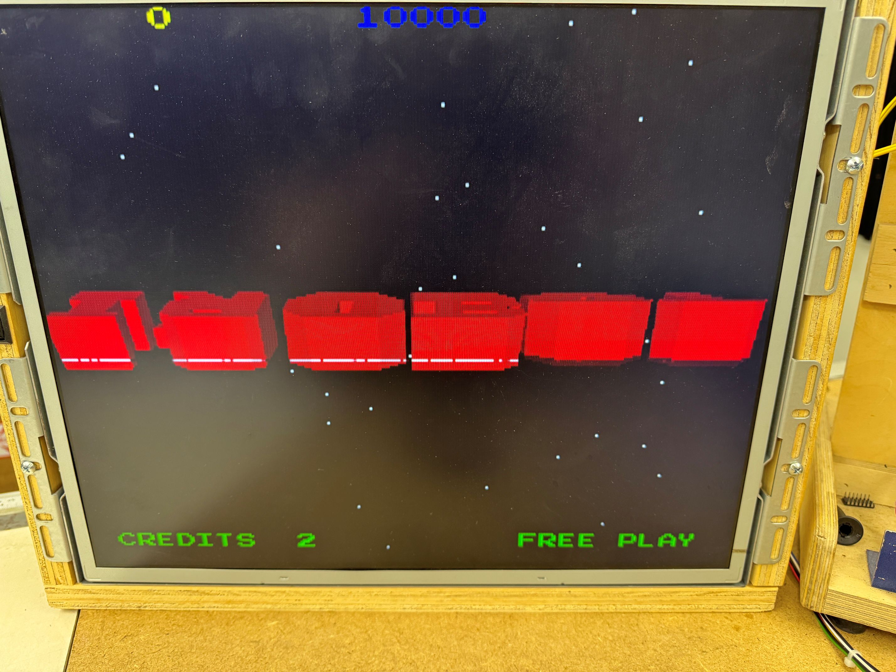
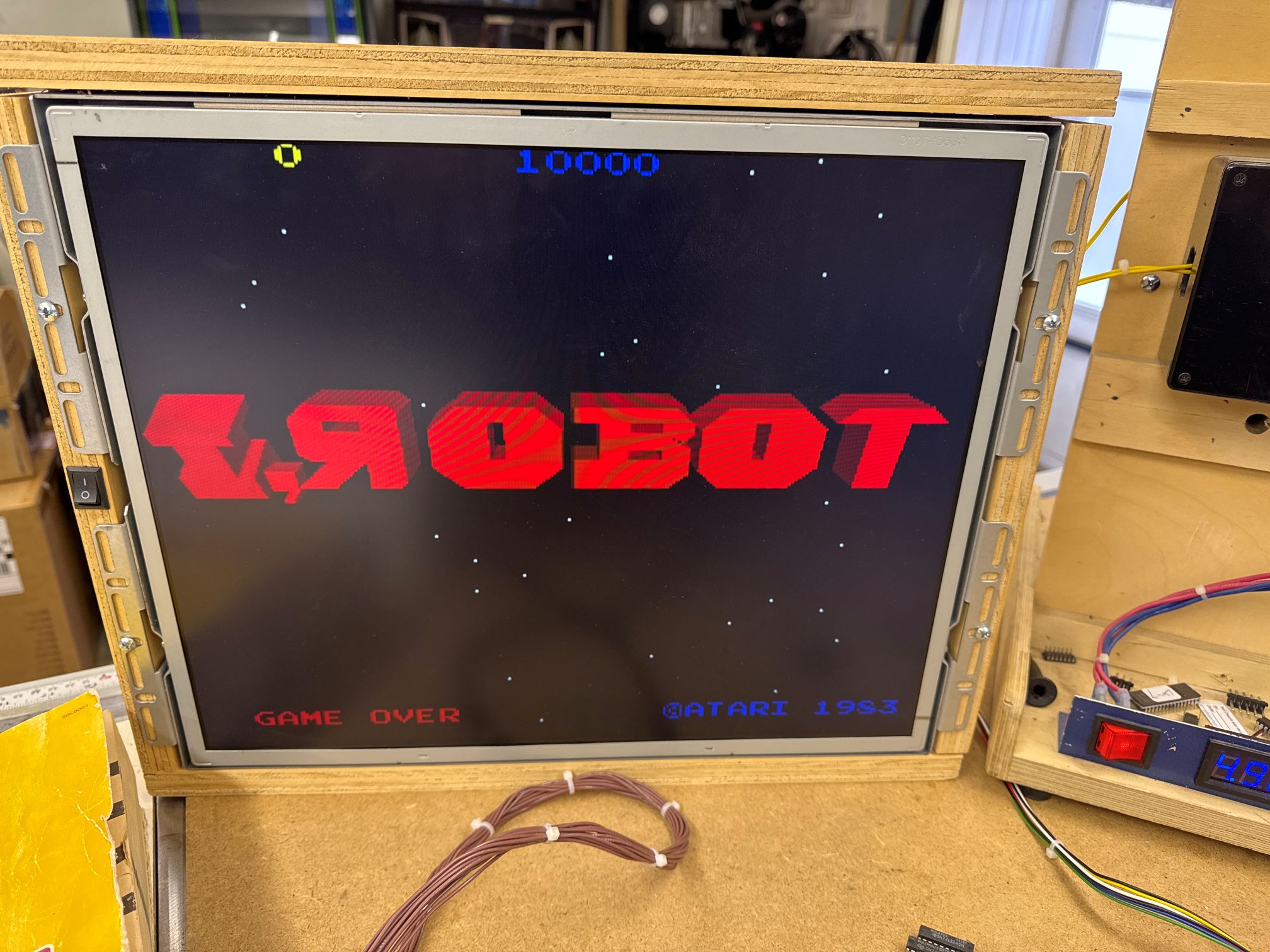
Here is what VP WONT STOP looks like in attract mode in my case, just for fun..
I,Robot has some nice built in self tests. One of them tests the Vector Polygon circuit.

It’s not the same, but it is very similar (to me) as the vector generator circuits in other Atari games. There is a /STARTMM@Pin1 7J and a DONE@5R Pin2 and a HALT@8K Pin12. I haven’t deciphered all of this, but VP WONT STOP reminds me of a vector game where control is transferred in and it never comes out (no HALT). That is what was happening here – DONE was never signaling and the majority of this circuit was dead.. A little blip here and there. Good news is that test mode stays in a loop on this circuit waiting for it to work. The PROMS @7C,7D,7H were all socketed. I swapped them with the other board – no change.. The S174@7J had been removed, socketed and replaced at some point.. no change with a quick swap.. I spent a while on this page and eventually I kept coming back to the S174@7J. Finally I put a comparator on it because it was still bothering me. It complained about Pin5. I lifted Pin5 from the socket and it went from 5v to toggling..
A quick check showed Pin5 was shorted to 5V. It made no sense because it seemed to be nowhere near a 5V line. I pulled out the LeakSeeker and it kept telling me look at the socket.

The socket was cleanly installed. I removed it and didn’t see anything, tested and the short was gone. Gave it a quick brush and put it all back.. Board worked..
For about 4 hours.. then VP WONT STOP came back..
I checked and Pin5 was being pulled high again – ok – it wasn’t the socket (which makes much more sense) I could not find a way for Pin5 to short to 5V here anyway. The short showed up testing the actual socket and went away when I pulled it.. weird.. that said…
I pulled out the LeakSeeker again searching for the short.. this time I found the real problem.
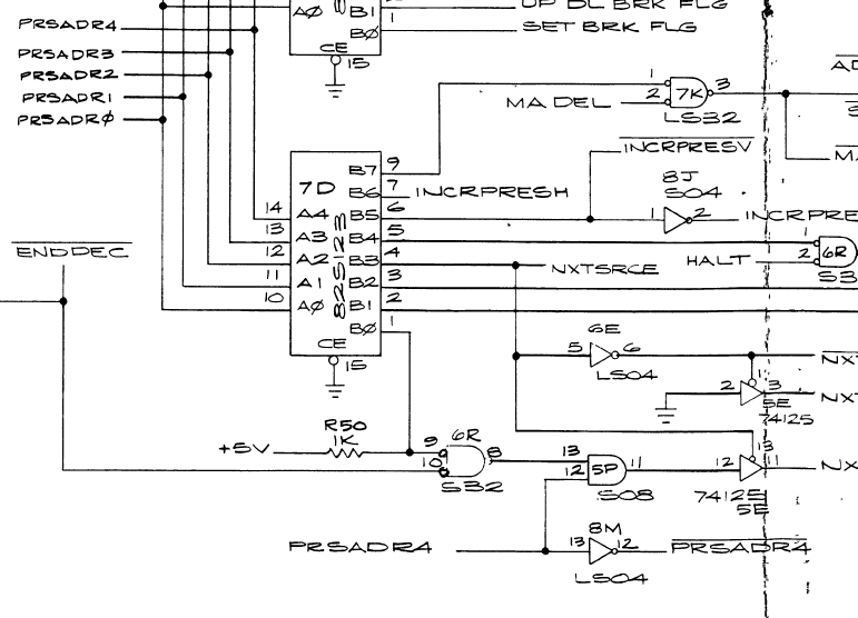
7J@Pin5 is tied to PRSADR4 – the first time I checked I missed that it was connected to LS04@8M. It was hiding in plain sight on the schematic.. Testing showed that 8M Pin13&Pin14(Vcc) were shorted internally. An uncommon TI chip failure. Replaced 74LS04@7J.

Board works!
*** Except once it got back to my friends house, it was having C0 memory errors. He swapped some boards around and determined the Video board still had issues.. ***
I got the board back on the bench and connected it all up – sure enough it was reporting memory errors on the video RAM. These are @1C, 1D, 2C, 2D on the video board. While testing and moving the memory around – I could get the error codes to change. Then one time it booted clean.. The sockets looked suspect and I replaced all 4 of them. Board ran for a while, until it didn’t.. really?
I then flexed and moved the board around and I could randomly get it to boot. Looking close..


On the backside of the board, this first pic shows a via that was not full of solder.. It visually looked suspect.. I filled it. Second pic was a LS157 that had been replaced in the past and socketed. This pin appeared to need more solder. Since filling these, board has been 100%. I think it needed RAM sockets, but one of these seemed to be the cause of the random memory issues. Physically moving the board and flexing would cause them.
Board works! (again)
Board #3 – In for repair – friend’s board that had issues.

This one turned out to be simple and interesting to figure out. I didn’t realize it was an issue at first since it went away within a minute and I’ve never worked on or played I,Robot. It’s not exactly Centipede or Asteroids.
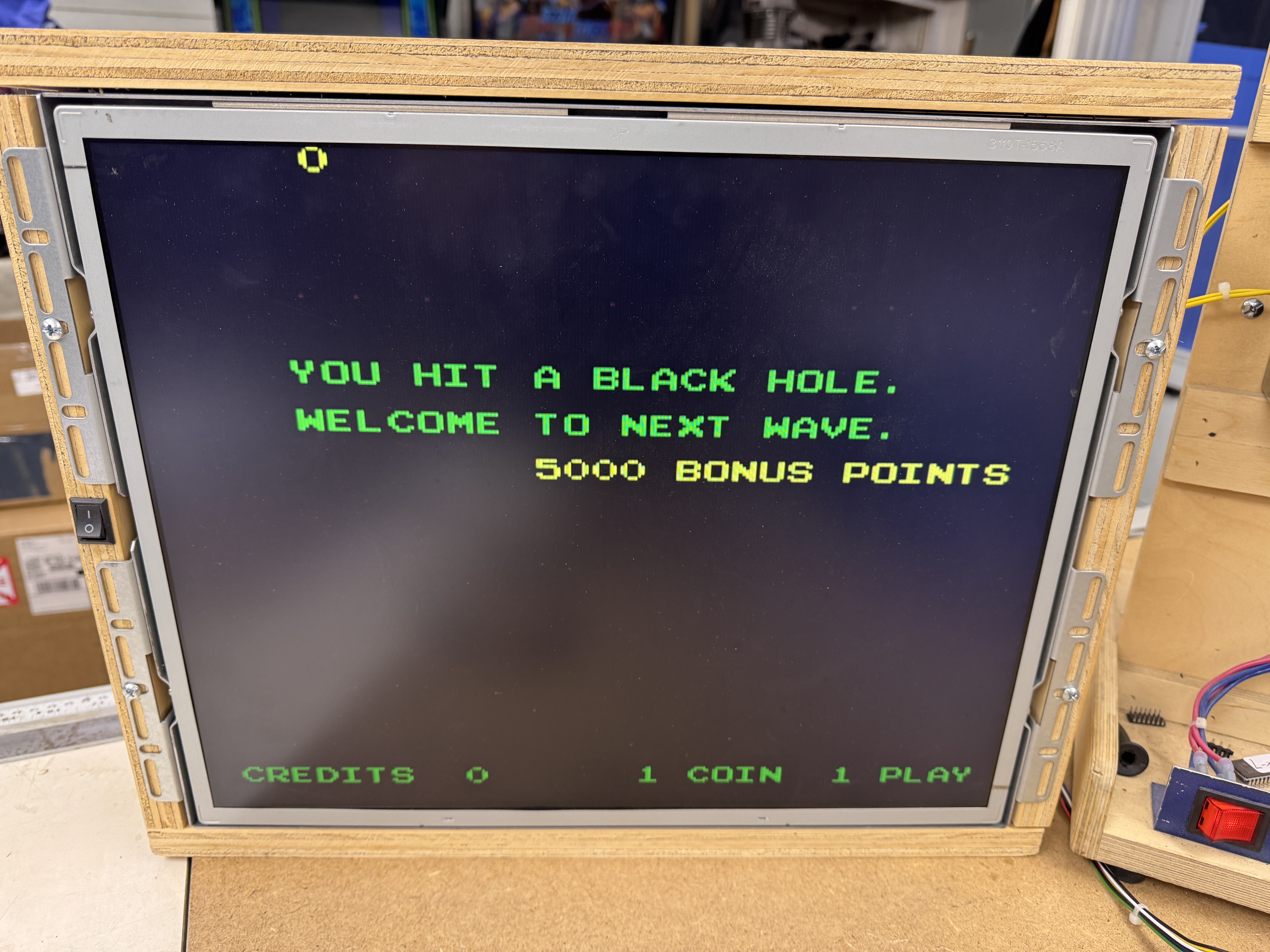
Similar to Tempest (and others) I, Robot has a ‘mathbox’ along with the vector polygon (vector generator) circuit. On I, Robot it has a row of PROMS and bitslicer chips on the CPU board (think Tempest AUX board). The “BLACK HOLE” error is the code getting lost in the mathbox it seems. Big difference between raster and vector games?.. Raster games can display a character error message when different parts of the circuit are broken. Vector games pretty much need all of that stuff to work just to draw the error messages on the screen in the first place.
Back to the error: I didn’t know it was a mathbox error at first. I did know that from a cold power on you “hit the black hole” – for about 30-45 seconds. Then the game started working as expected. Classic thermal chip failure. I have a can of freeze spray and I spray one column of chips at a time. Got to column 9 and hit the black hole quickly. From here I spray one chip at a time until I find the offender. PROM-120@9M was the troublemaker. I swapped one in from the other board and the game boots immediately. Normally thermal failures are the other direction. Chip works and then fails after a minute. Here is the much less common, doesn’t work until it warms up failure. Once I determined the PROM was failing – it became obvious the “Black Hole” on I, Robot is the mathbox. I didn’t see any reference to this in the manuals.

Board works!
Board #4 – In for repair from a friend
This one has the less common quad Pokey with the visible traces, very pretty!
Of the 4 – I,Robots – this one put up the biggest fight. I started simple, I connected the video board to a working CPU board and it ran fine – just had some graphics glitches.
In test mode they present as dotted horizontal lines through the color bar test screen. Probing the ram, finding dead outputs and replacing RAM@11L, 11M and 12M corrected the problems and the video board was all set.
The CPU board took a bit longer.. Partially because I sorta skipped a step and mostly because I’ve just started working on them.

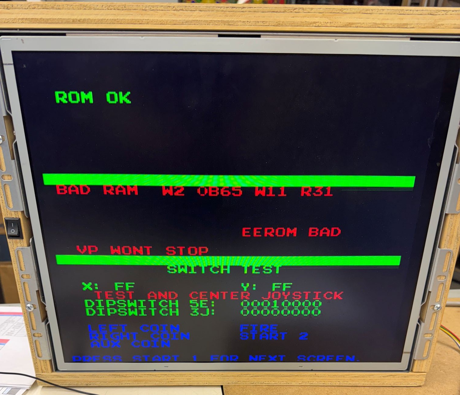
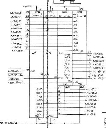
Self test was showing problems with the mathbox ram. It’s saying there is a short at this memory location (which sorta makes no sense) It was my kill screen. If you removed all 4 of the mathbox ram, you could get ROM OK and RAM errors. I could even put 3 of the RAM in place and still get the machine to come up to this point. The 4th ram@2N would cause it to fail to the first screen again. I could put a single RAM in and get 2 ROM failures or swap the RAM to the other bank and get the other two ROM to fail – some sort of bus corruption for sure. From here I spent some time trying to determine what that one RAM was connected too causing all of this..
Spent more time than I would like to admit trying different combinations of RAM and ROMs to see if I could narrow the cause.. I found a signal that when you added the last RAM it dragged this one down, chased it for a while.. Mixed in there was it was enabling both ram banks at the same time when this was happening. Eventually I was able to backtrack through the circuit and found what was causing the drag down and enable issue..

My buddy tried to help by cleaning chip legs.. Except he swapped the PROMs @7M, 7N accidentally – /MBMEMDEC@7M Pin 14 was the problem after backtracking through the RAM issues. I should have compared the PROMs to the working board.. At lease I could get past the kill screen now! This was the step I missed.. But the mathbox not running can kill everything, that I do know now.
Except, board got worse.. It would just boot into a garbage screen, really? At this point if I pulled a mathbox ram I could get back to a simple ram failure.. My thought as it was now just getting lost inside of the mathbox after the RAM test completed. I spent more time trying to trick the board into providing more clues.


Somewhere along the way I removed this bitslicer@4/5K and the board unlocked! Good clue! Plug it in, board locks.. Now to determine which of the 40 pins were causing it..
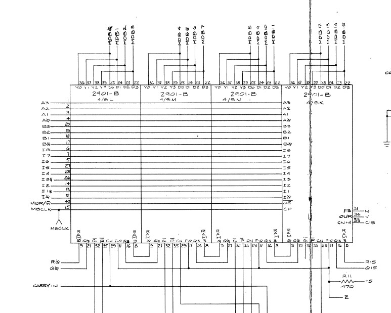
From the schematic, I figured all of the address/data lines were ‘likely’ ok since only this individual bitslicer chip was causing the lockup, the other three removed had no effect. I lifted the N,V and C15 legs so they would not go in the socket.. plugged it in and the board stayed unlocked.. I then eliminated C15. N & V went very few places thankfully..

N & V go into LS86@10A and LS04@4j. The issue was the output @10A pin11 had a signal on it that wasn’t part of the input. The S253@3M had some pins that could have had parts of the signal and could have had some internal short – So I removed it.. Signal was still on pin3. Then I removed the LS86@10A.. Signal was still there with nothing connected.. A SHORT! Beeped my way across the board until I barely spotted this..
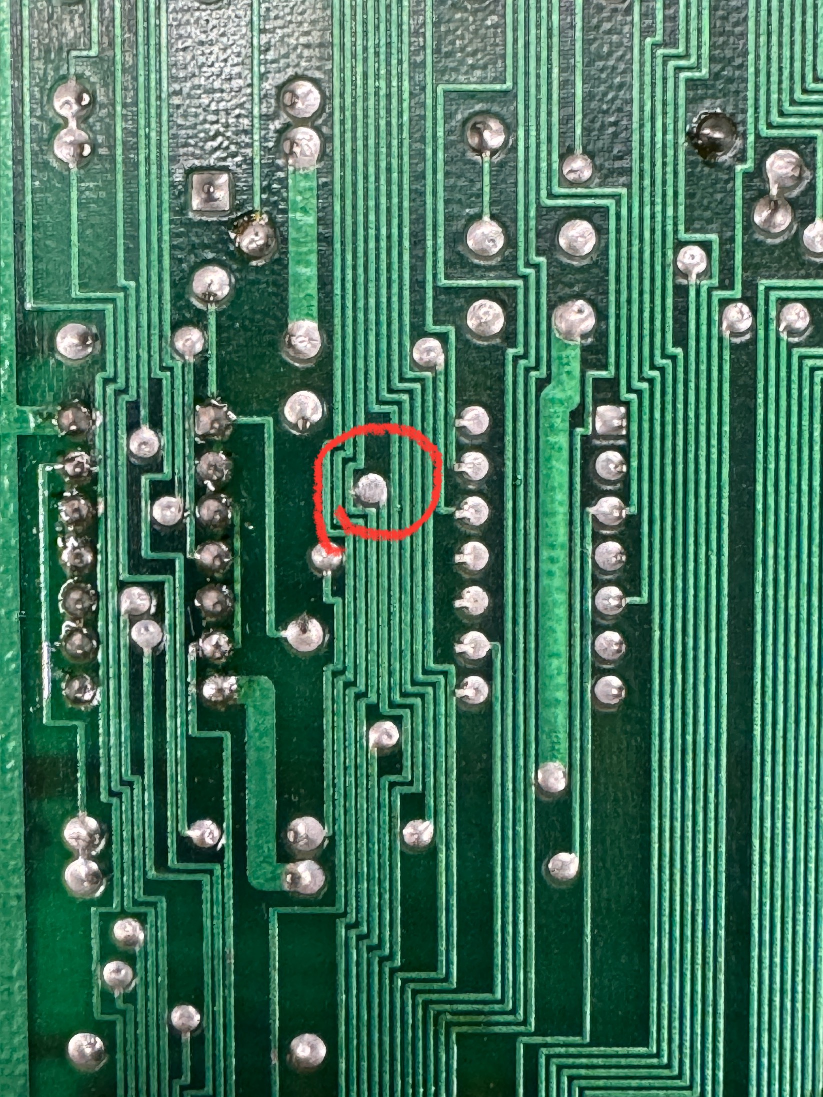
This is factory.. It is just a tiny whisker that must have creeped over time.. Don’t know. One quick swipe with the soldering iron and it cleared. Put all the chips back and now the board would boot with all of them installed, a first!
Except… Still getting mathbox errors. I still had a fully working board with PROMs that had good legs. A swapped all of them onto the board but still had problems. I started swapping Bitslicer chips and one of them after being replaced changed the error.. Reset the machine and it started working! I swapped all of the original PROMs back and got yet another mathbox error.. Grrr.. I then swapped one at a time to find the bad one.. It was the last one of the group of 13 PROMs.. Had I started at the other end it would have been the first.. Needs PROM-112.

I was able to create some random memory errors on the same video ram as the other boards. These particular sockets on I,Robot are the Atari single wipes that I’ve had good luck with in the past. But they were also suspect. I replaced them and the graphic glitches have gone away.
Board works!
Board #5 – In for repair from a friend
One more, really? really.
This one was more of a ‘can you check it out, I get some graphics glitches’. One thing I learned is that the RAM on the video board seems to be pretty sensitive (Star Wars is similar in that respect) Sockets were also suspect and I replaced them. I think it may be a good idea to just do them on all I,Robot sets. The graphics issues were reported to be happening during an arcade party – but normally they were pretty hard to reproduce. Through testing of a couple of the sets, the boards do not like to get too warm.
I put one set video board down on the bench and ran it a while.. Plenty of graphics glitches. Without powering it down – I elevated the board set (using spacers) and pointed a small muffin fan at the stack.. came back a while later and played a normal game, no glitches.
If I were to guess – the RAM is the cause and maybe new ones would help? But a cooling fan that can circulate over the stack would be best I would think.
Board works!
Likely the first time this has happened since the factory..
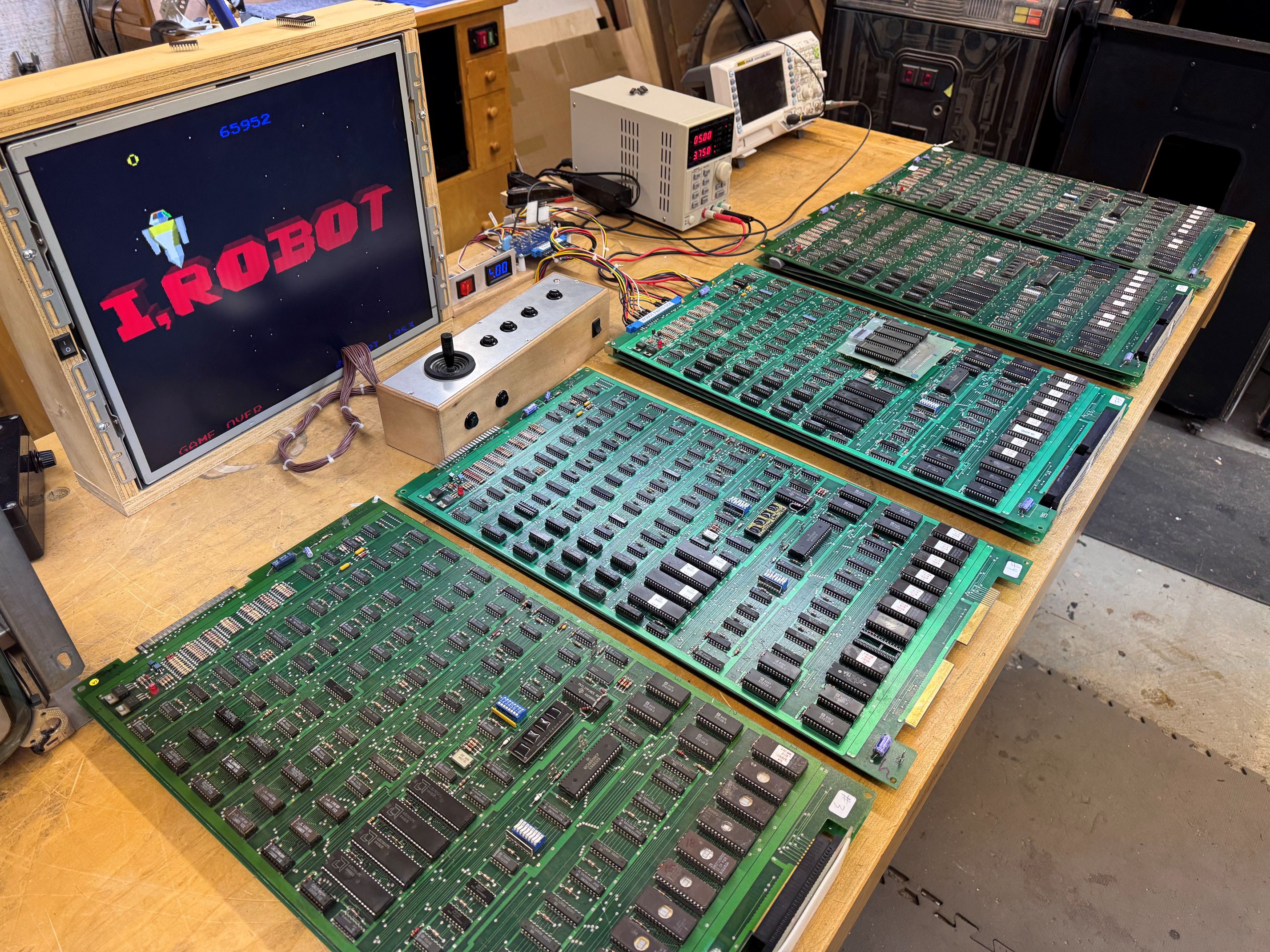
5 sets of I,Robot boards in the same place at the same time.

Amazing work! You’re the best, Bob!
the big graphics processor needs a fan- thats where your thermal glitching comes from.
in the original cab there is a big fan under the stack that pulls cold air in through the pedastal and blows up across it.
I did determine there were thermal issues. running the boards hot made them glitch like crazy.. thanks 🙂