
Got a request from an arcade I’ve done some repair for in the past. Could I fix a couple of Atari Football boards? After taking a look at the schematics, I couldn’t see why not..
The way I test boards is to use my Test Bench and Adapters


This one was a bit different than most. Power was simple – but took a little planning. Football is pre-ARI/II days and the board does its own voltage regulation using AC inputs. I’m using the 10.3vdc and 22vdc connections from the bench supply and that passes through the regulator diodes. It also uses 2 trackballs – I just need to test functionality vs have a 2 player game running on the bench. I made a P1 and P2 connector for the trackballs and can test both sides by just swapping the inline connections to my controller. One other item was the original control panels used LEDs to show you what play you are choosing. I had made one of these little LED displays for Lunar Lander which does shows your selection the same way. As luck would have it, Football is common anode and Lunar Lander is common cathode – so now I have two LED displays for bench adapters. If there is ever another game with LEDs on the CP – I’m ready for it! I didn’t need to make the LED display, it’s just fun. I could test the game board directly if I wanted too.. The adapters take a 2-3 hours to build and test – but after that testing any board takes a few seconds to connect and you know the setup is 100%.
Board #1 – In for repair

Both boards came in and are in really nice shape for the most part. Once I got the board powered and voltages verified I worked on a FPGA Tester config. The memory map is relatively simple on Football. I can also see how some of Atari’s later designs evolved from this one (and probably games before it). From what I can tell, Centipede and Warlords use a similar (identical?) video memory layout. I can also understand how the ARI and ARII came to life. The voltage regulator and power resistor get hot – the resistor gets burn your finger hot.. After running it a few hours on the bench while in the shop, there are no ill effects. That said – if Football doesn’t have a cooling fan – I recommend it unless you bypass the on-board regulation and use different power.
First item during testing was the work ram was not being accessed properly

/PFWR not functioning.

Working backwards, the 7432@B4 was doing its job, the /WRITE was not working.

7400@C3 – not working correctly. Replaced it and we can now write to the RAM. Moving on to testing ROM – @M1 wasn’t reading. Quick test with known good ROM – same thing. Checked and the select PIN20 was not toggling.

Working backwards, 7432@B4 had no output on pin8. Replacing it corrected the ROM read.

Board works!
Board #2 – In for repair

The voltage regulation section on these early boards get hot. The resistor gets “you will burn your finger” hot (ask me how I know..) The first couple of hours of testing I was in the shop just to keep an eye on them. Both boards work the same.. I have a small fan on the bench ‘just in case’. I’ve burn in tested over 12 hours without issue..
Once powered up.. no clock.

74161@P5 Pin12 had no signal, which killed all the the clock divisions down stream of it. Once replaced – ROM read good, RAM was not addressable.
Interestingly, 7400@C3 was bad again. 2 for 2 on this one.
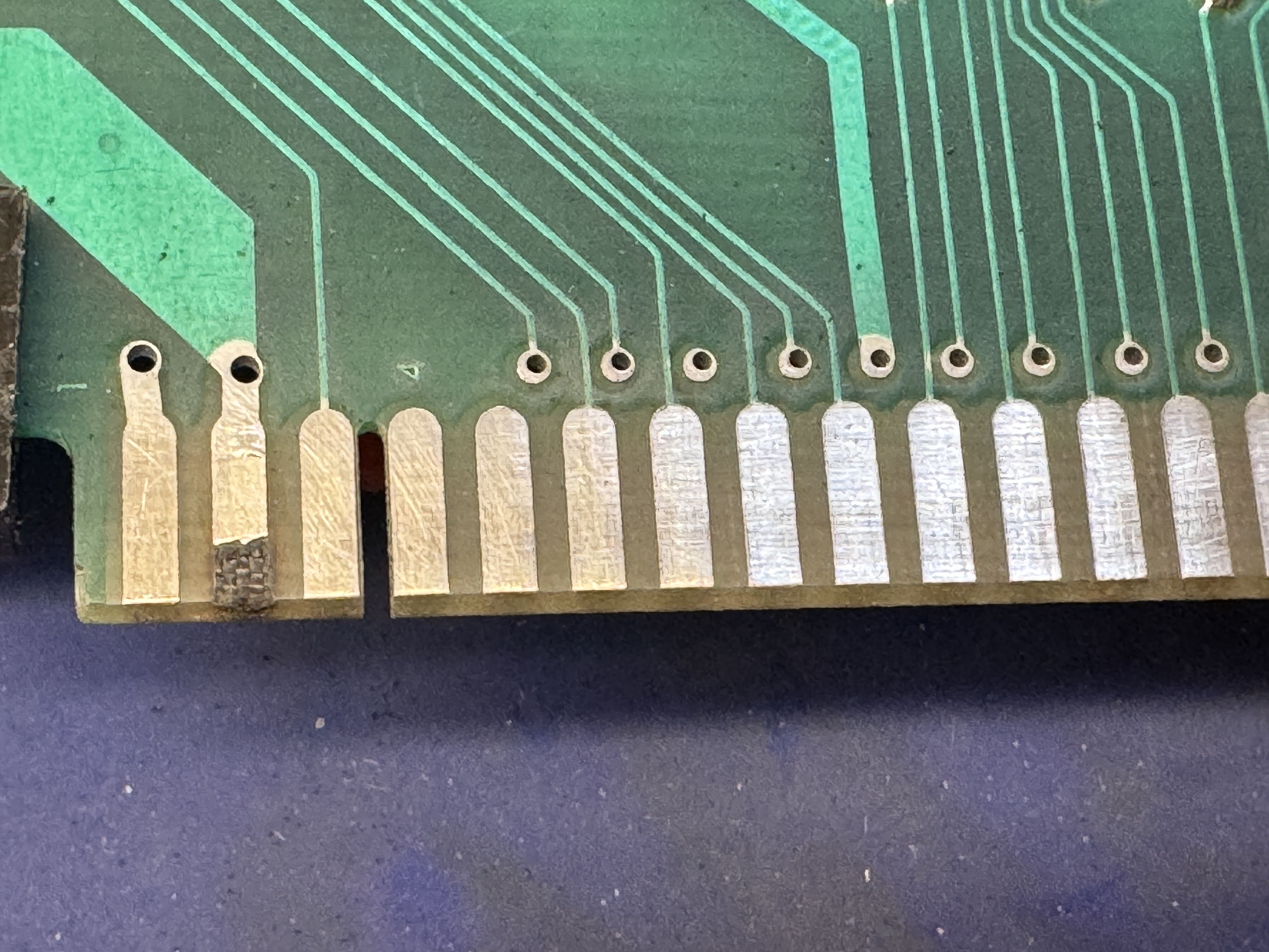

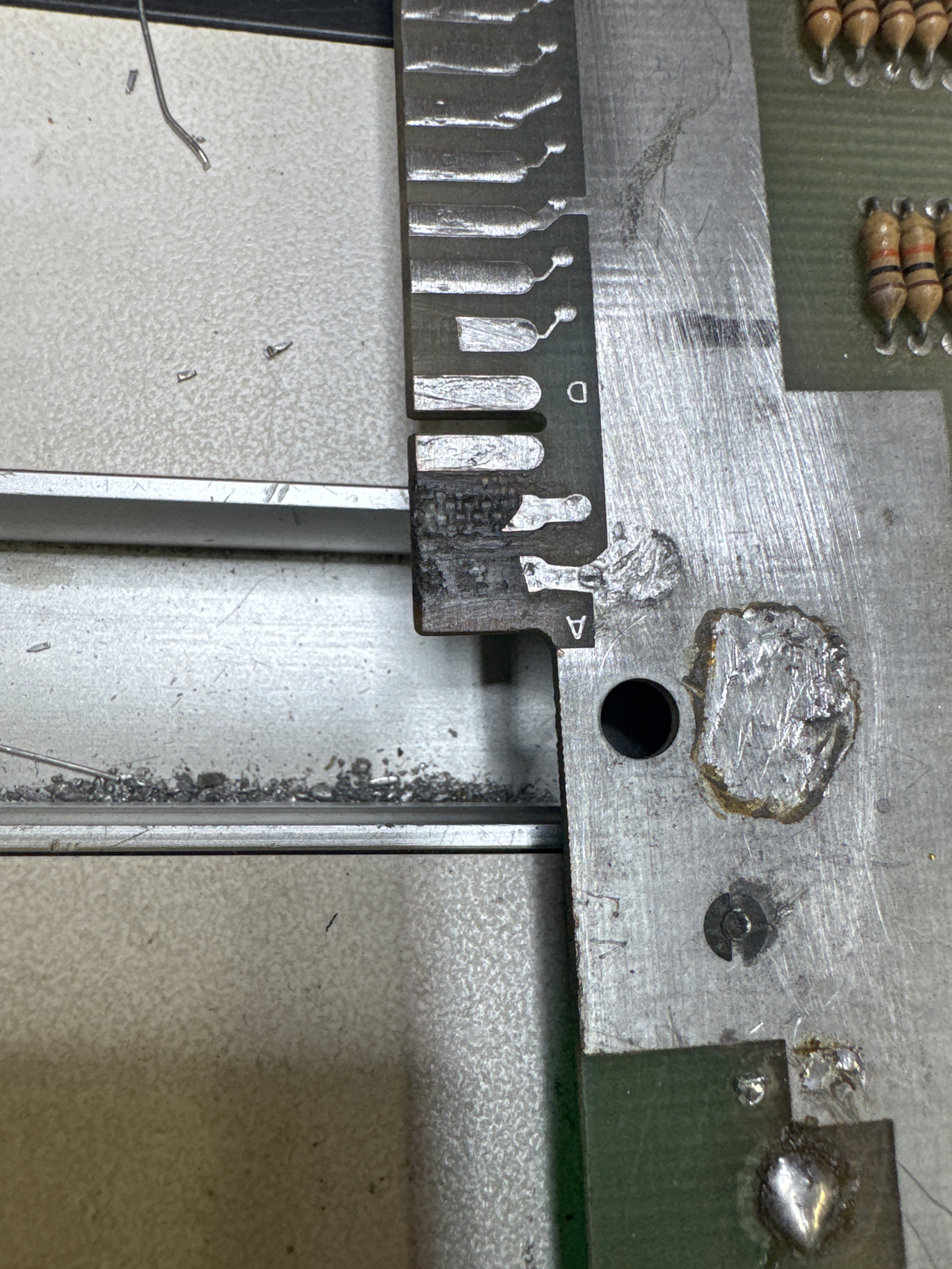
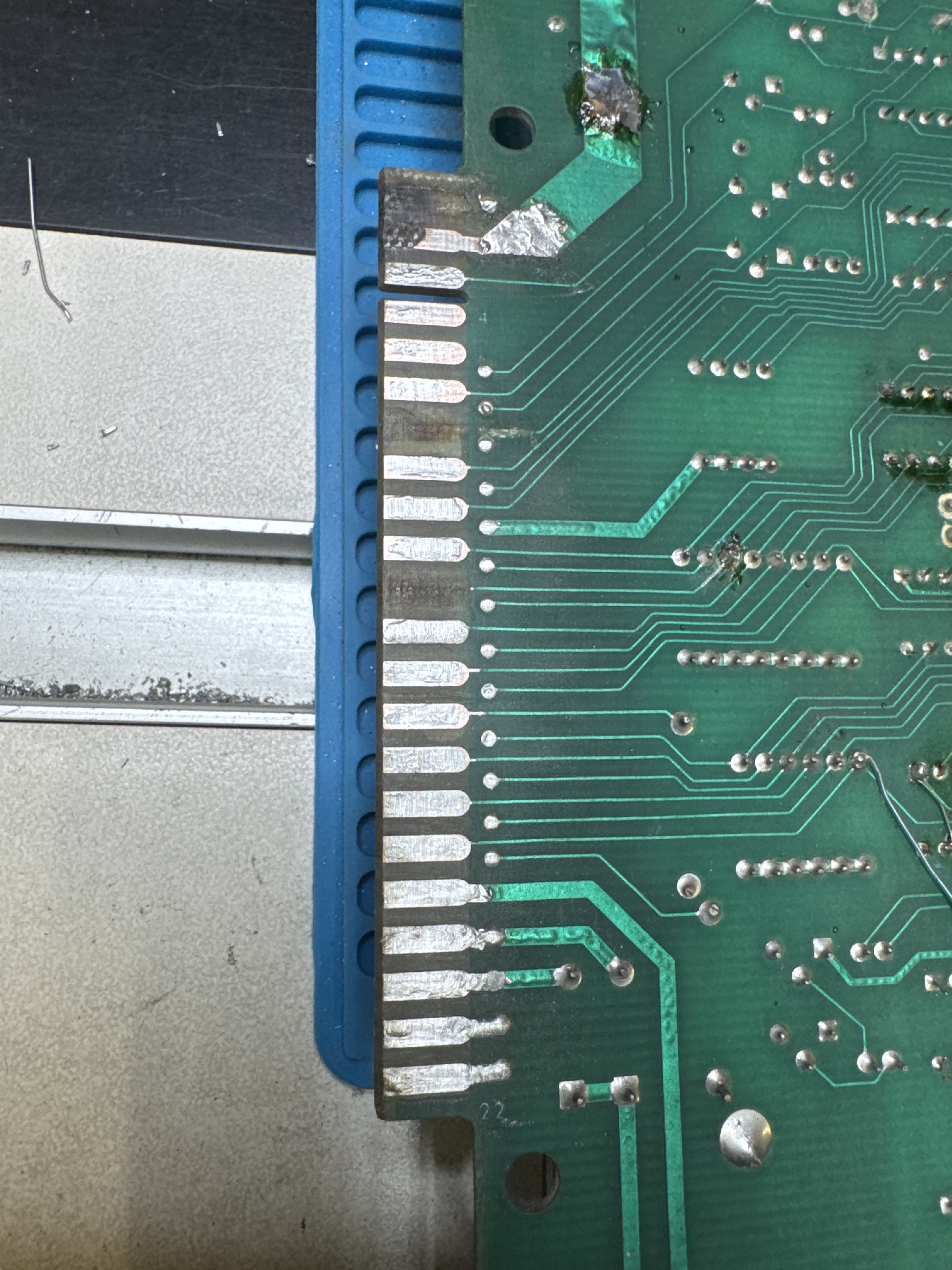
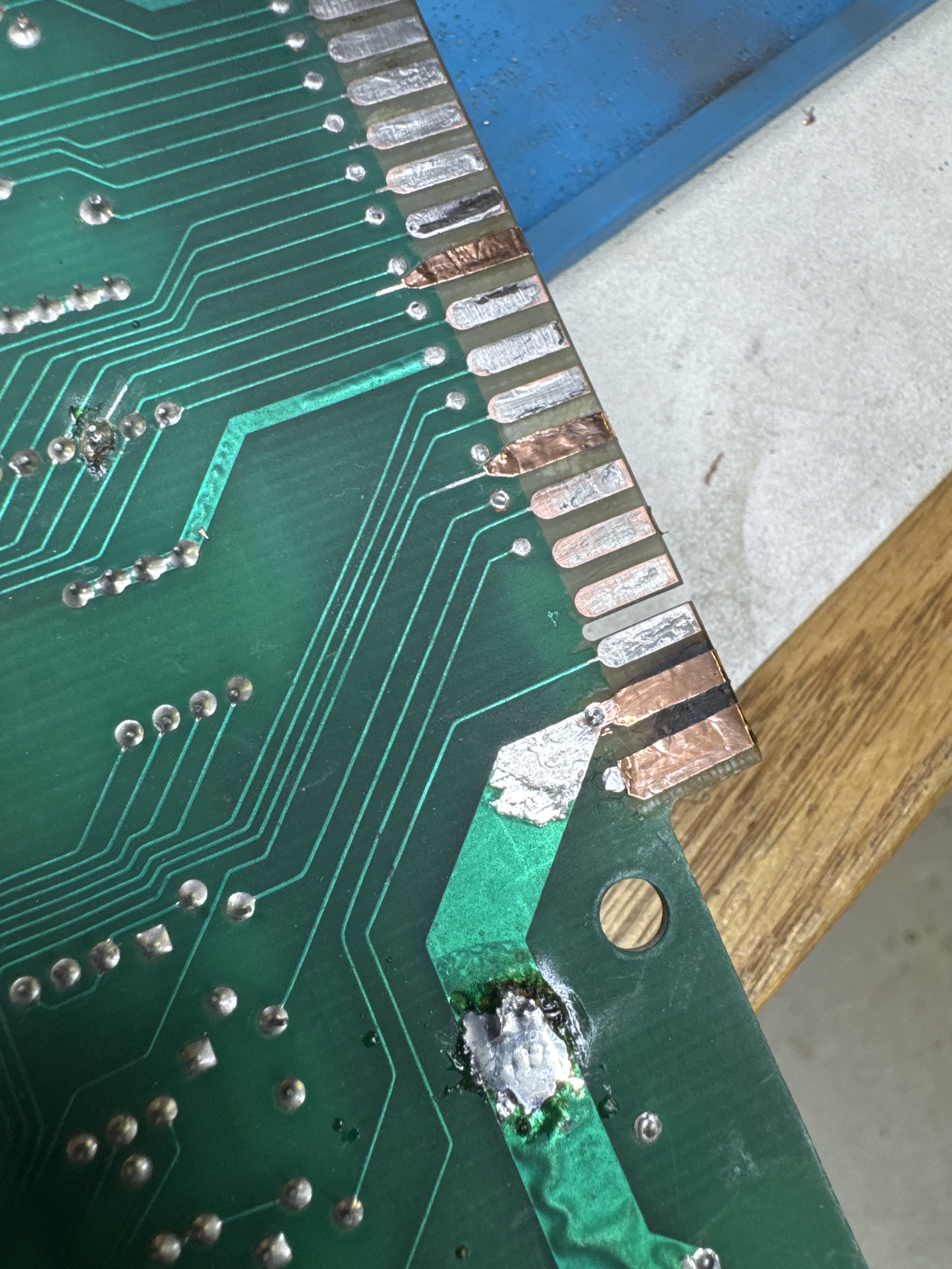
One of the fingers was burned up on the edge. It got cleaned, copper tape and then liquid tin. The tin helps prevent the copper from oxidation. Board1 did not have damage, but some of the copper was starting to show though from finger cleaning. It got some liquid tin to coat the copper.
Here are the play select LEDs in attract mode.. That’s just fun..

Easy to score a touchdown against no one!
Board works!
Board #3 – In for repair
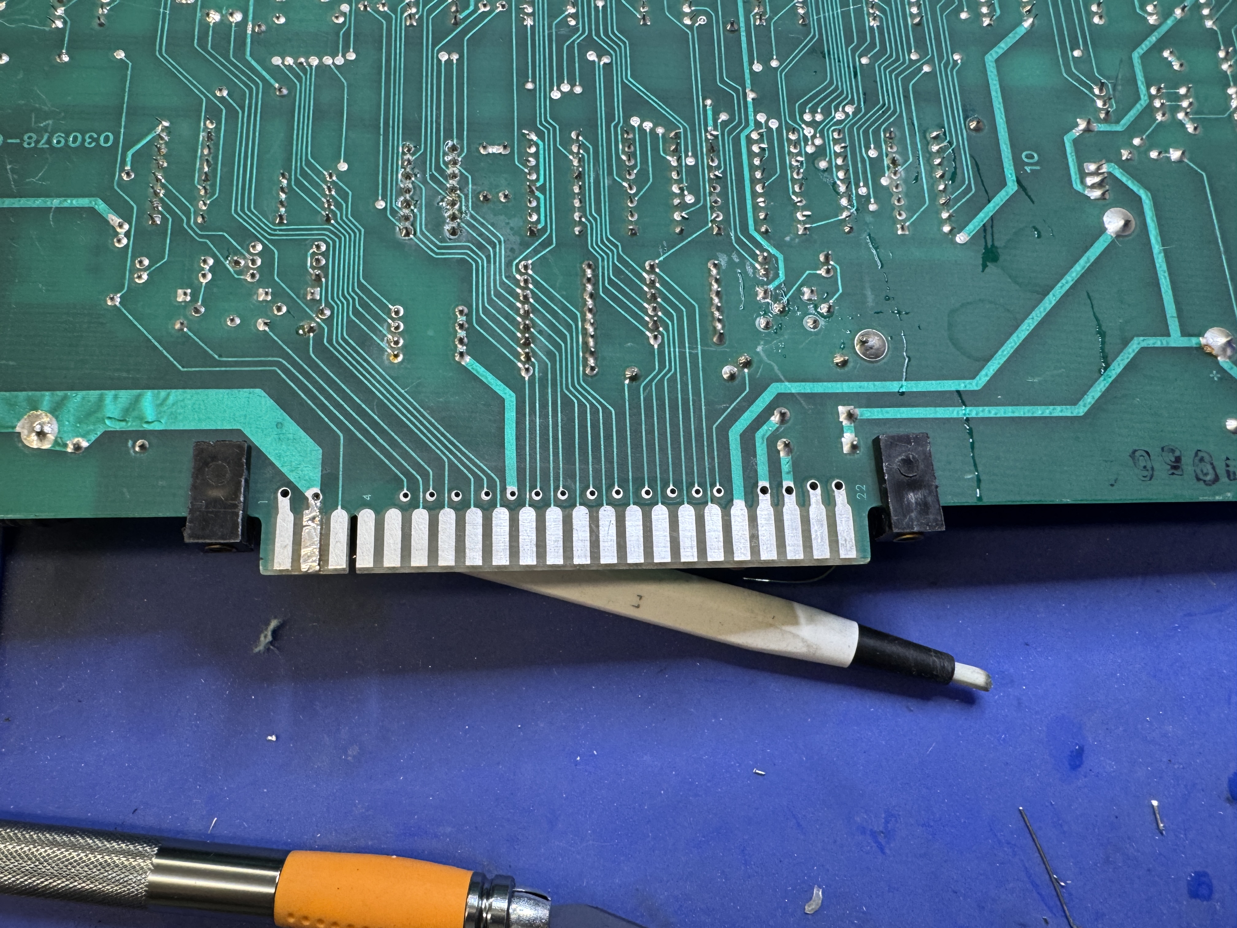
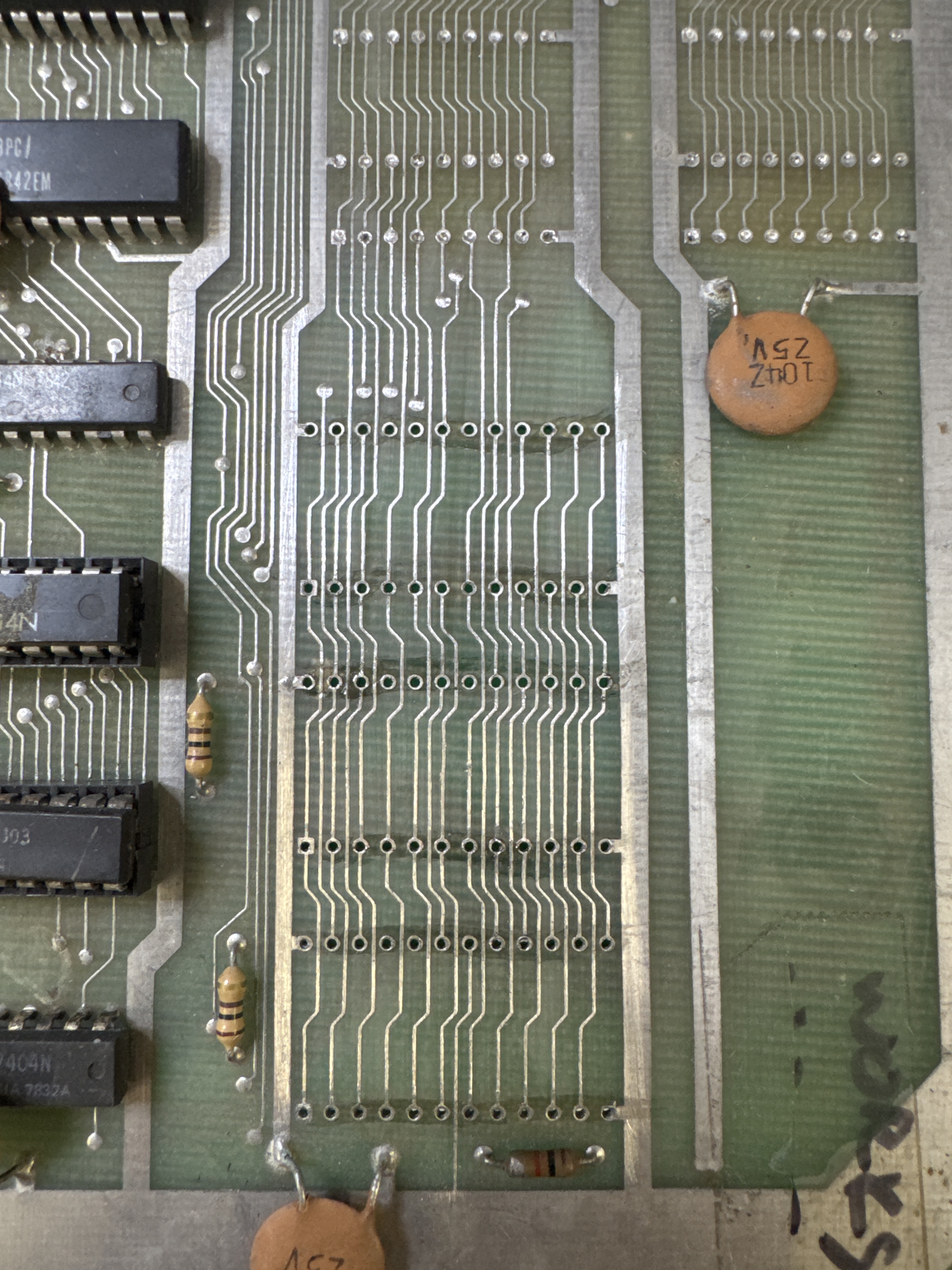
The board had its CPU and ROMs moved to the other board since this one needed extensive edge repairs. The edge connector was in poor condition and needed attention. The machine pin sockets throughout the board also required replacement. This one came in with #4 below.. I actually did #4 first because this one was in such bad shape.
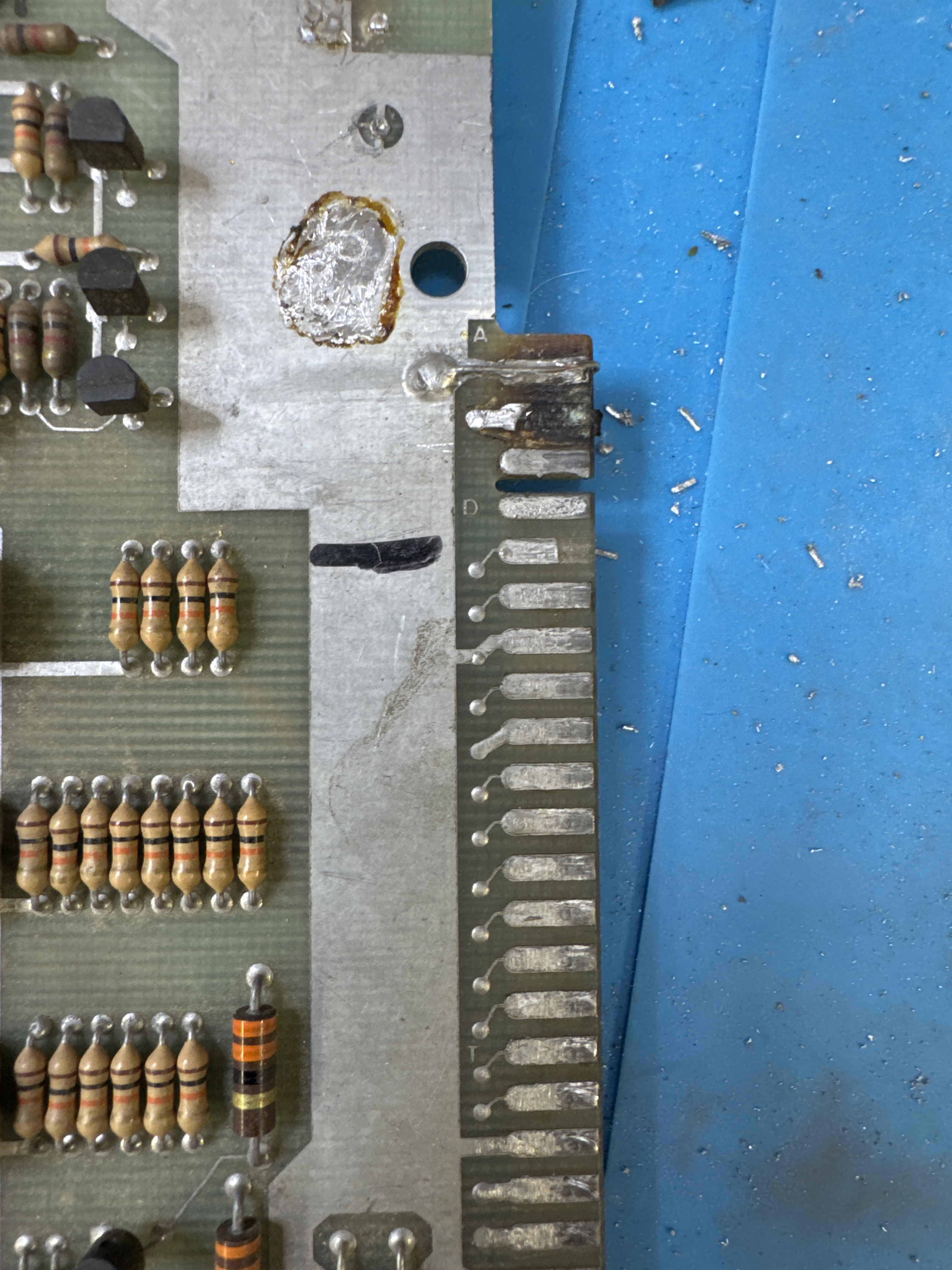
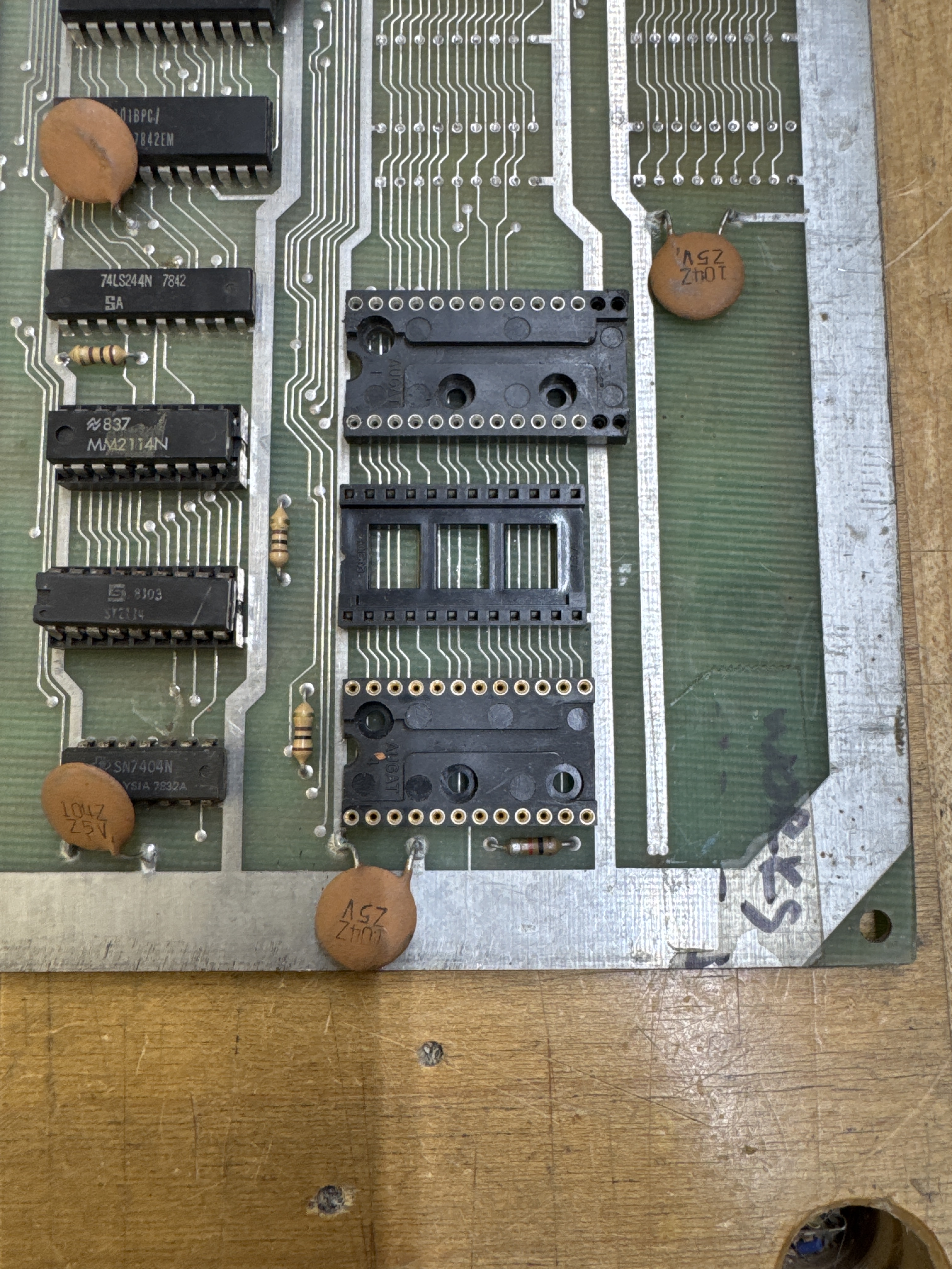
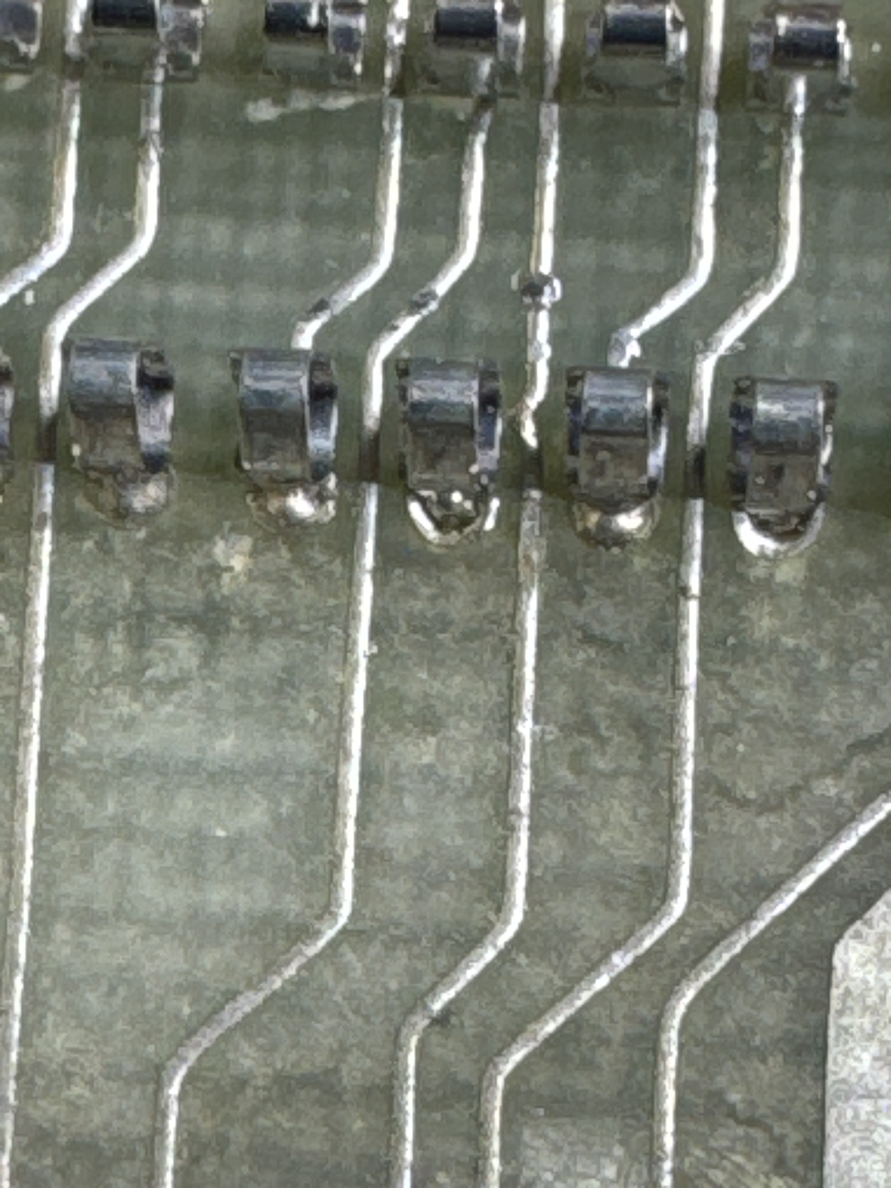
This is essentially where I started. All of this was a bit of a mess.
The CPU socket was original and came out cleanly. In the past, I’ve had issues with machine pin sockets being over sized and sticking in the vias and tearing things up.. These came out clean too.. I’ll take that!
I won’t post all of the pics, but I’ve become pretty skilled at getting this repaired and reliable.
Once I got the fingers repaired and liquid tinned.. hooked everything up.. No video..
Found this guy and replaced it. After that, found another issue with a missing signal.
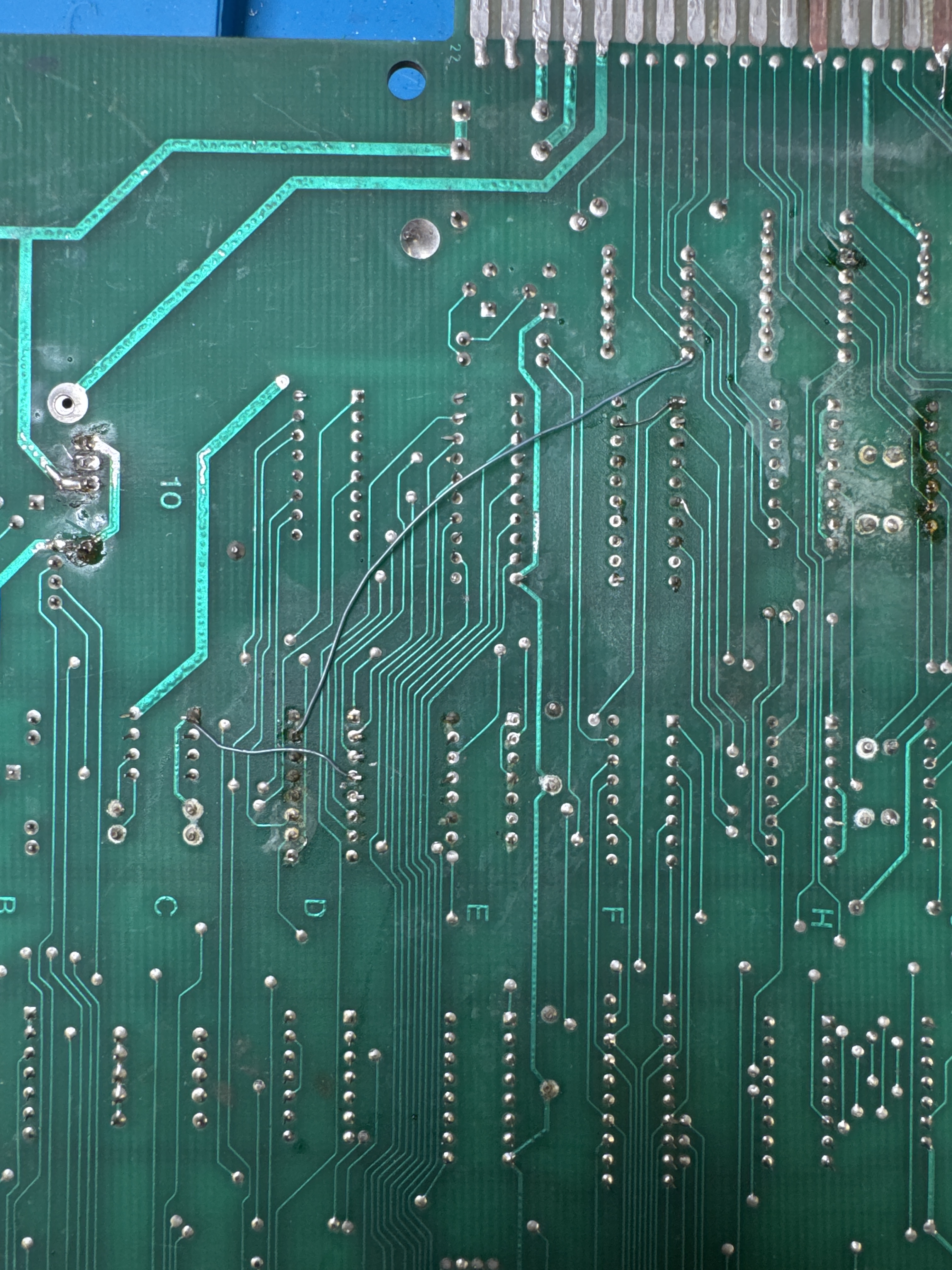
At some point someone socketed a chip and tore up some traces.. and then cut some more on the parts side. I repaired all of that, removed the jumpers on the back of the PCB and put a good socket in place.
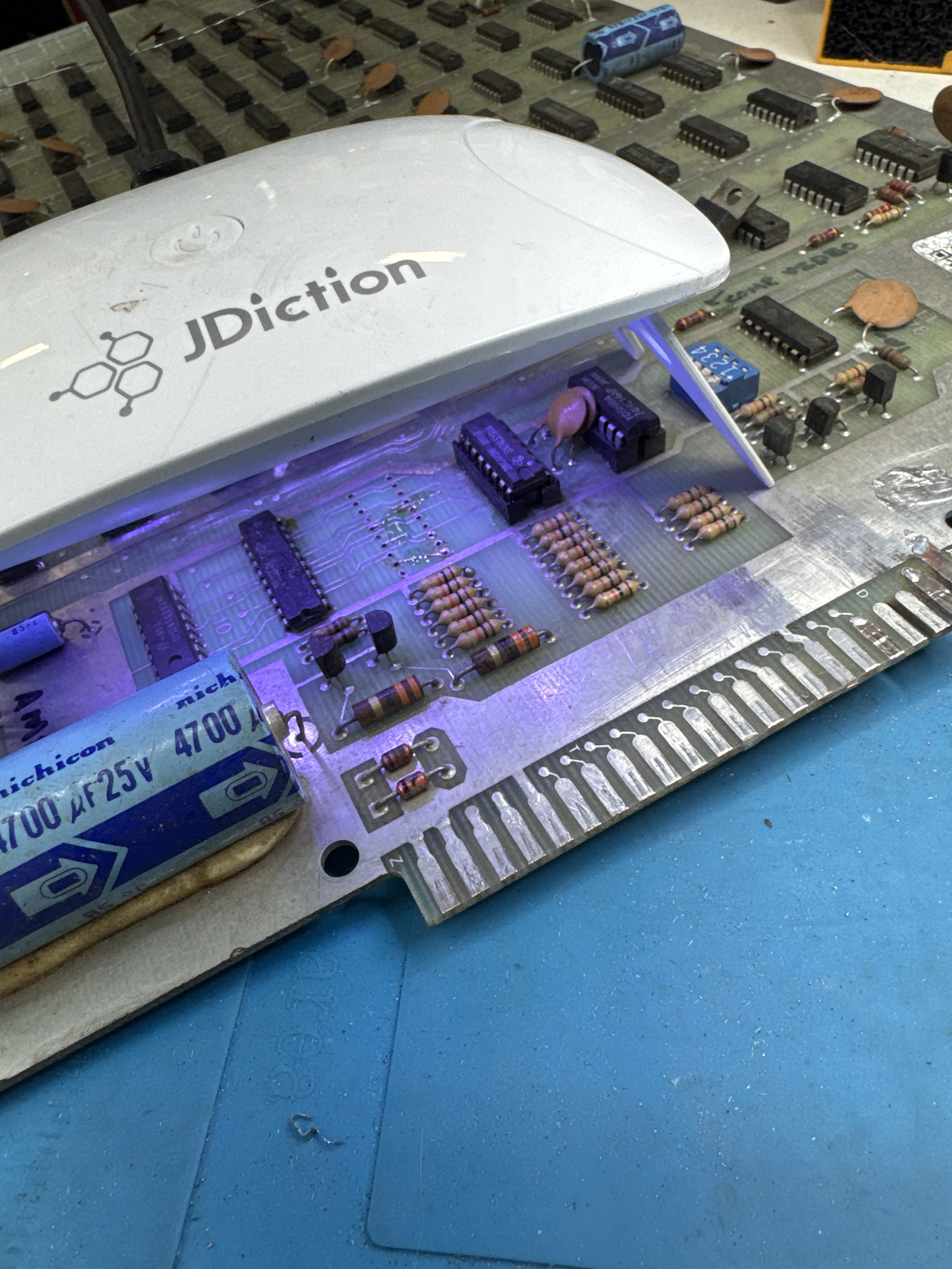
Here is UV cured resin locking the Kynar wire in place before adding the socket.. Makes the repair nearly invisible. Also had a broken 1000uf cap in the audio circuit.
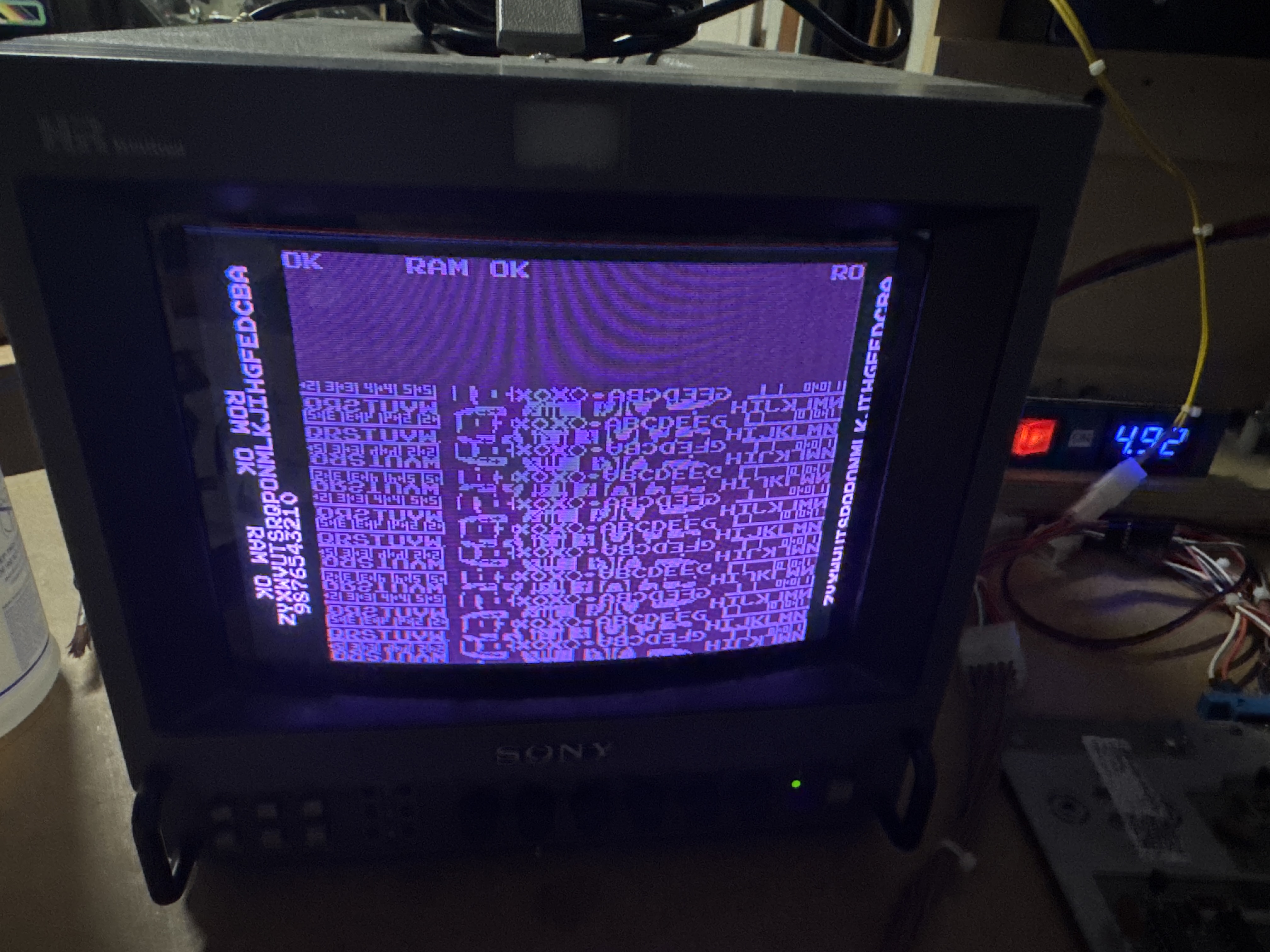
Here’s DIAG mode..
Board works!
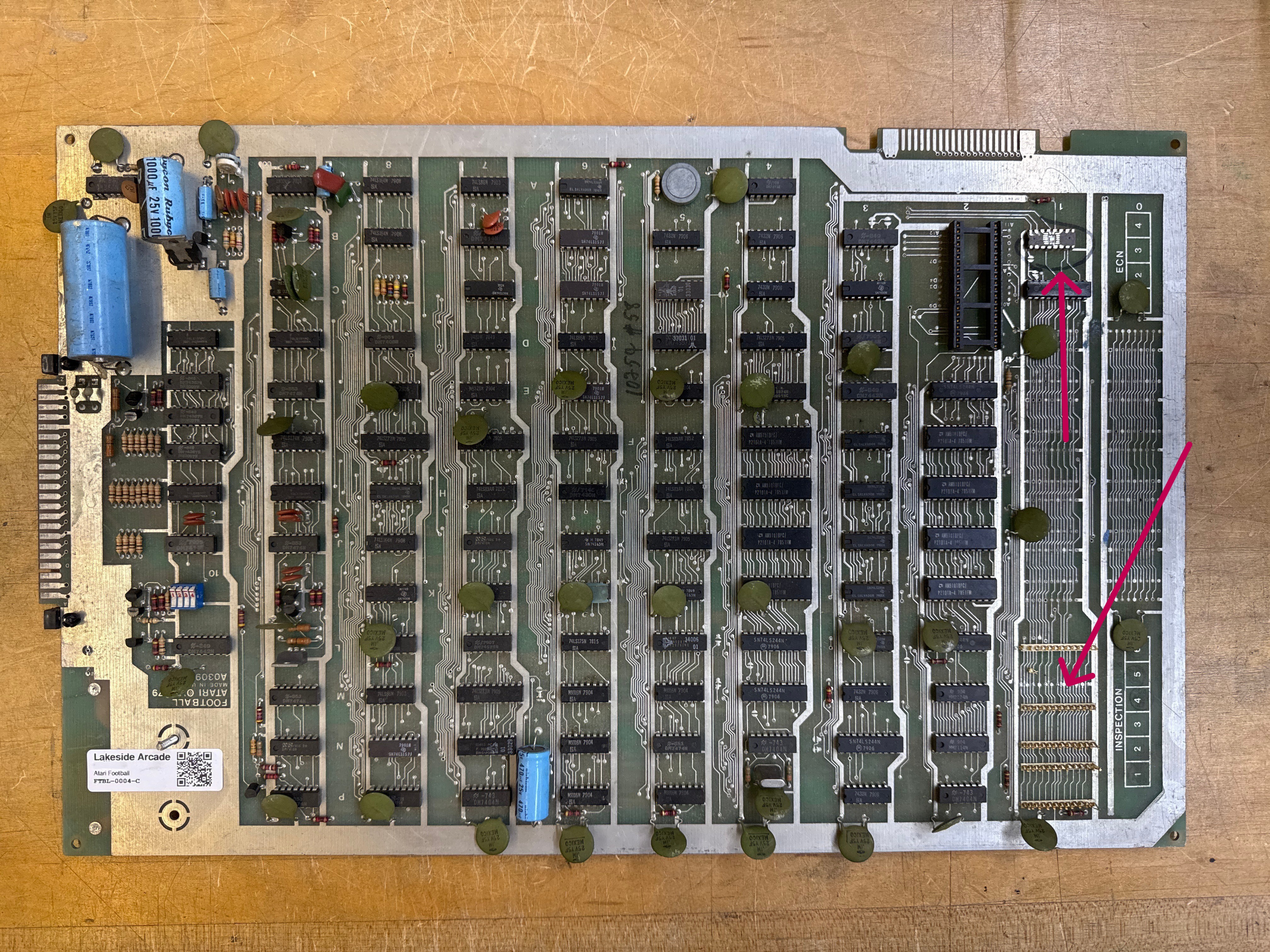
Board #4 – In for repair
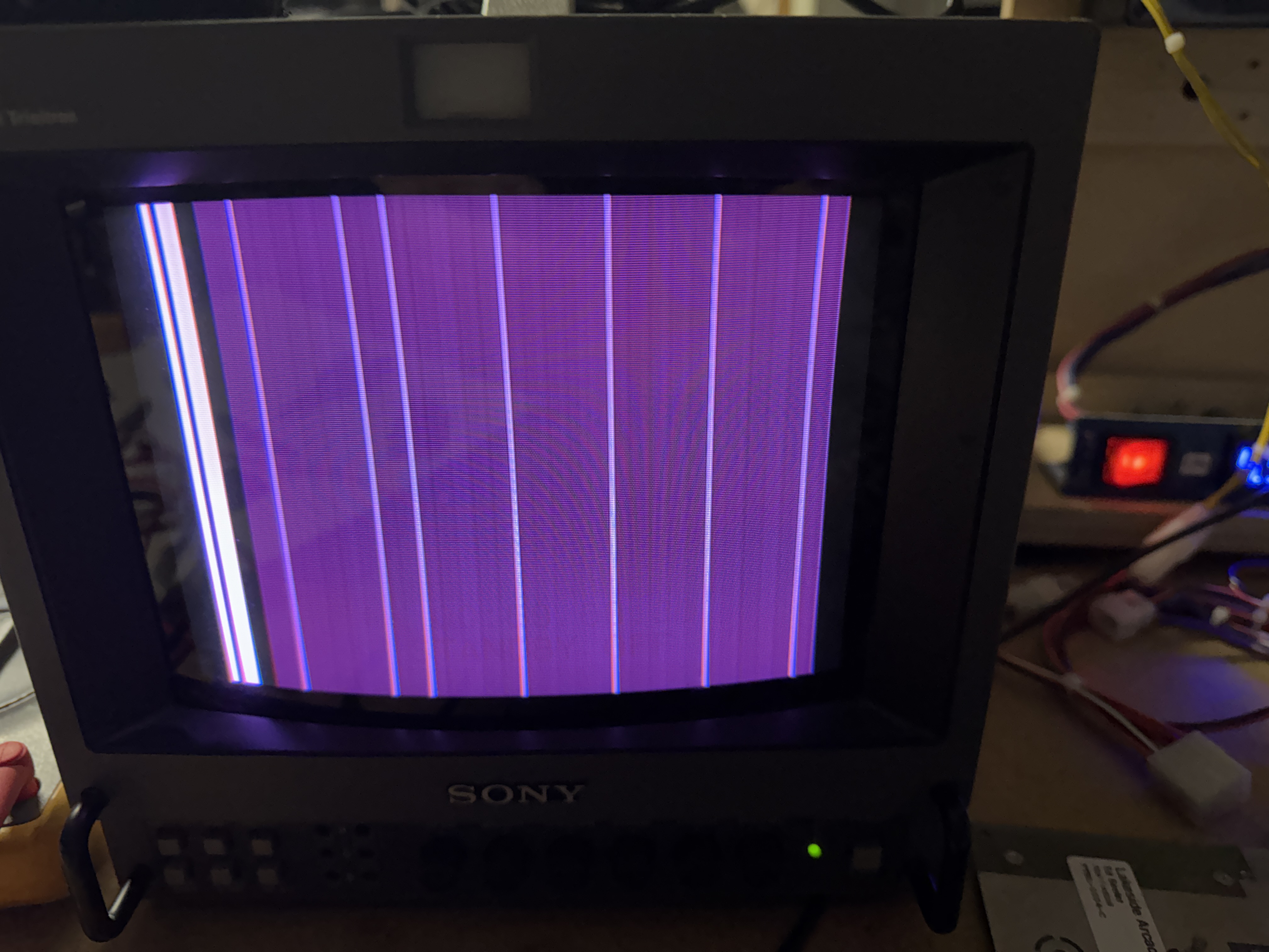
The board arrived with damaged or missing sockets and no ROM chips or CPU installed. It had vertical bars on screen, a missing vertical counter signal, and video sync issues causing a twitchy display. The reset switch was keeping the game stuck in a reset loop.
I actually repaired this before #3 because the edge connector was in nice shape. It still needed a lot of work.
- Replaced all damaged and missing sockets.
- Identified and repaired a short circuit on the board traced to address bus line 6.
- Replaced two faulty RAM chips.
- Replaced the vertical counter chip (9316 at board position 5M), which resolved the vertical bars and restored the playfield graphics.
- Investigated the sync instability; the sync PROM chip at position L5 was suspected but tested good and was not the cause.
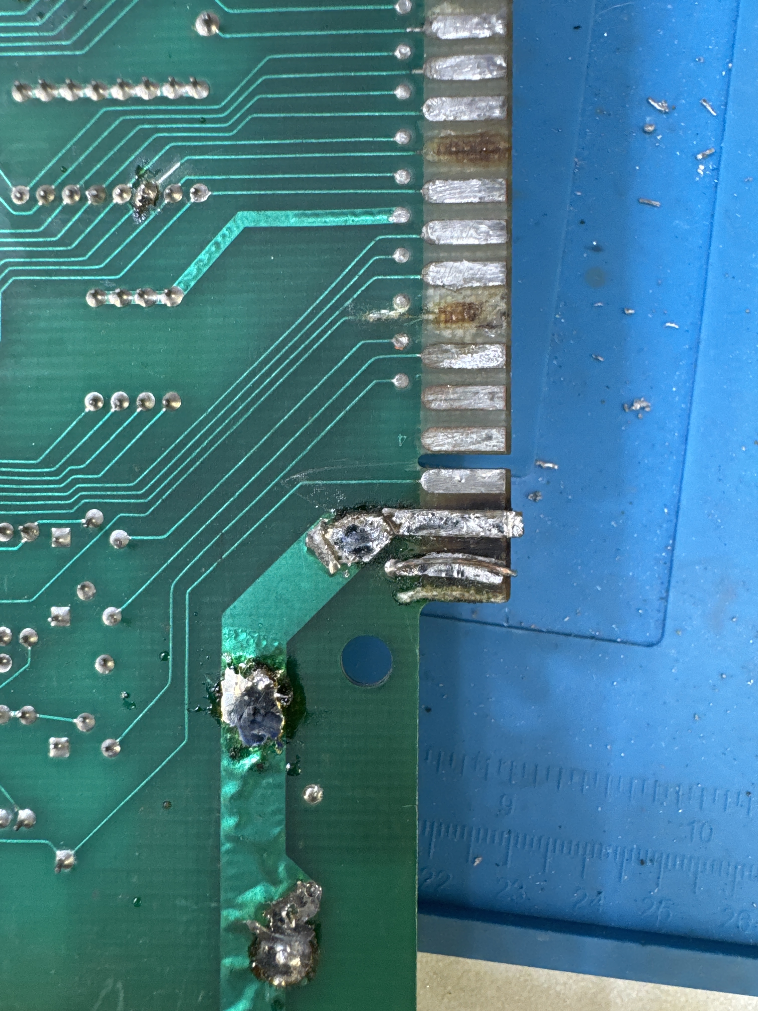
- Traced the sync interference to a shorted pin on the back of the board; performed a thorough close inspection of the entire board to find and resolve this.
- Added a heat sink to the audio amplifier chip to improve thermal management.
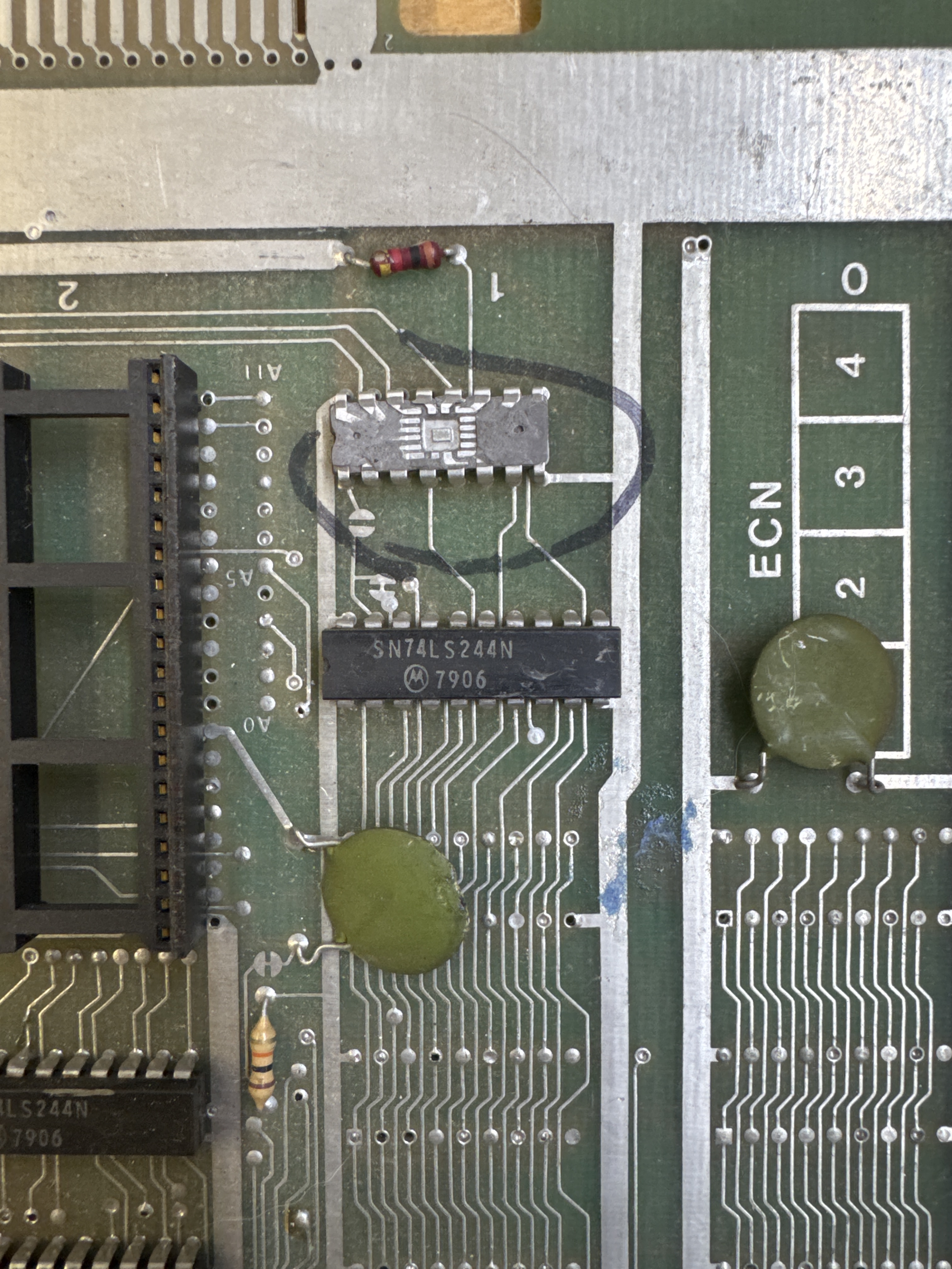
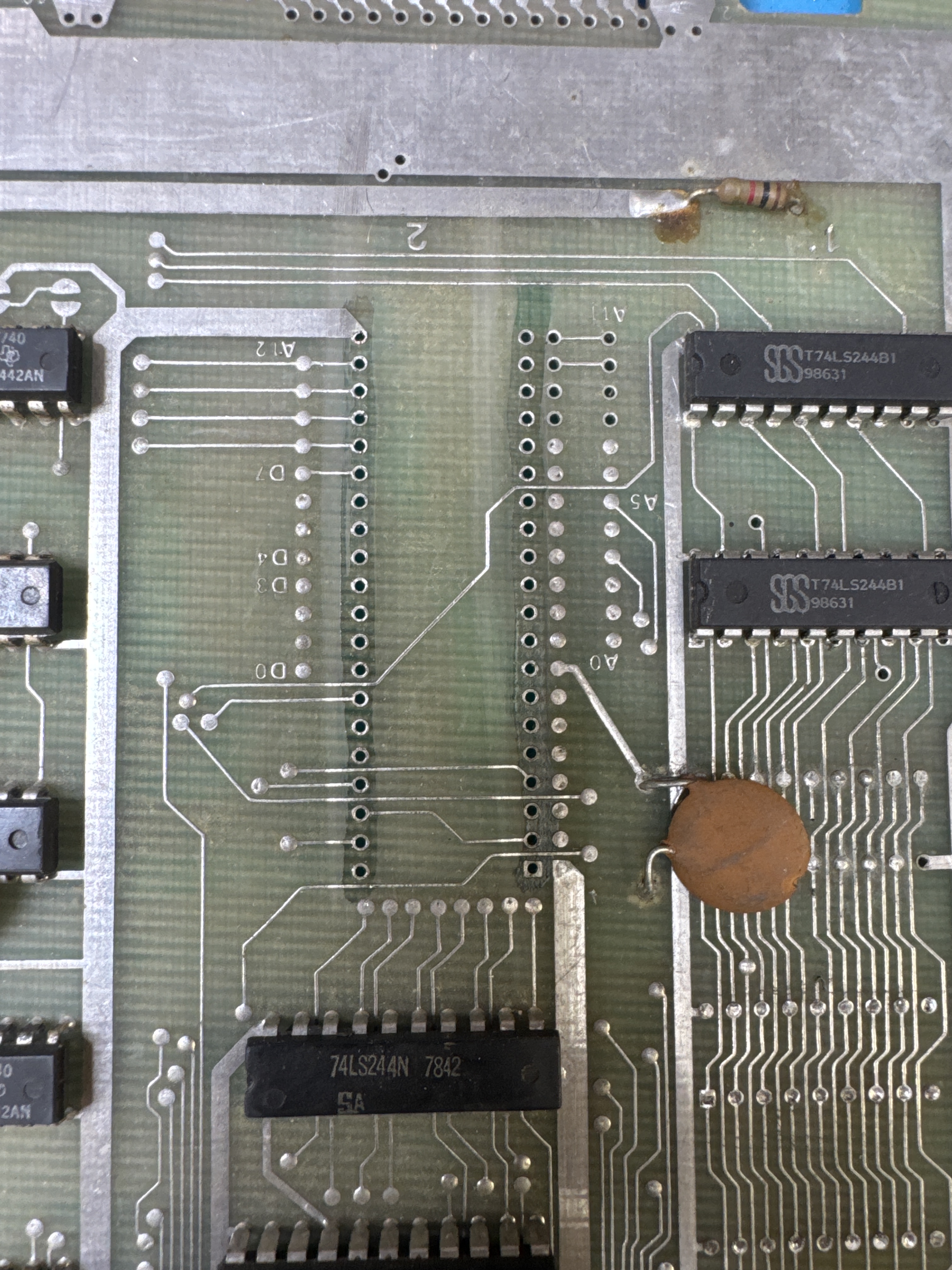
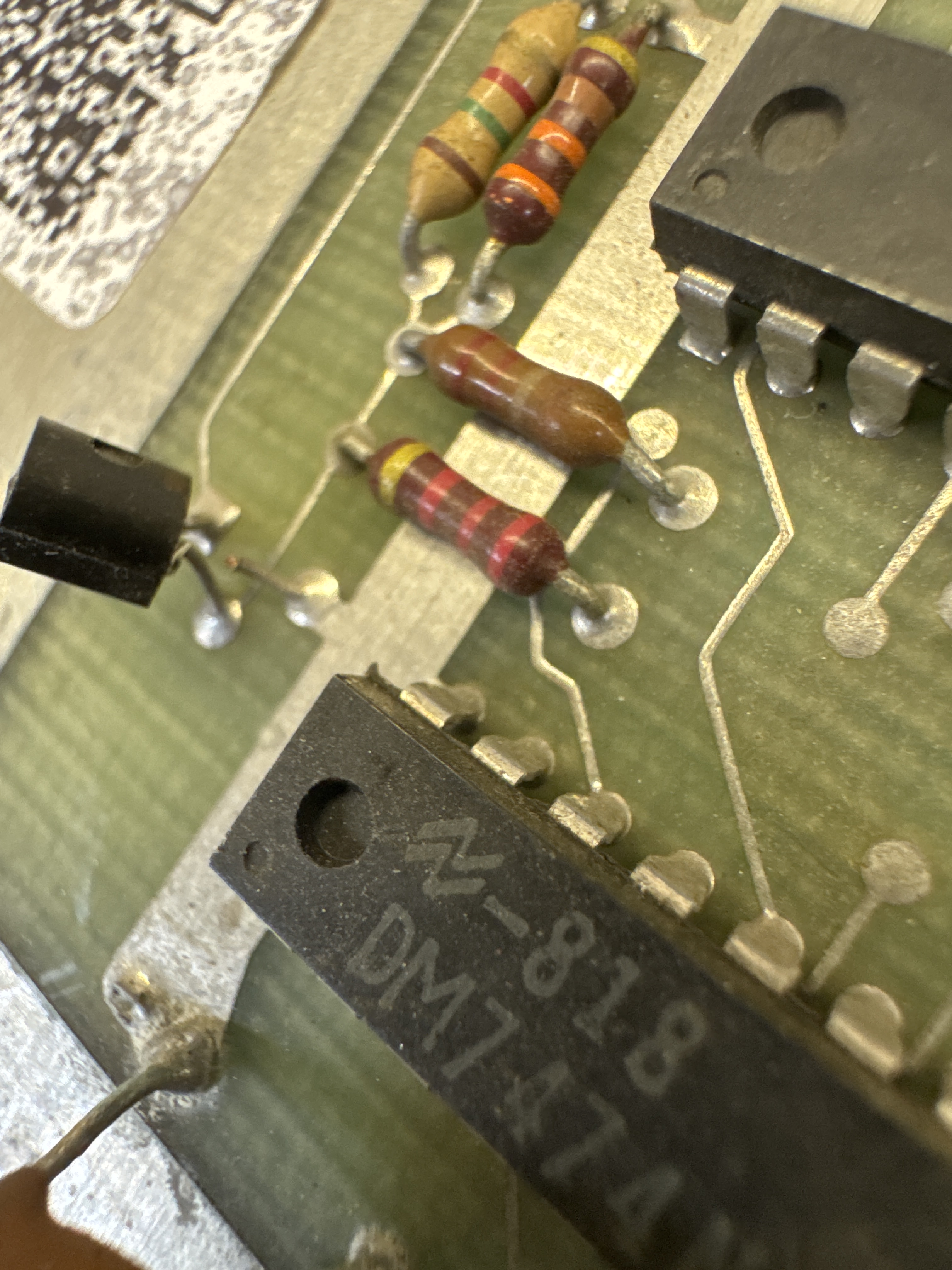
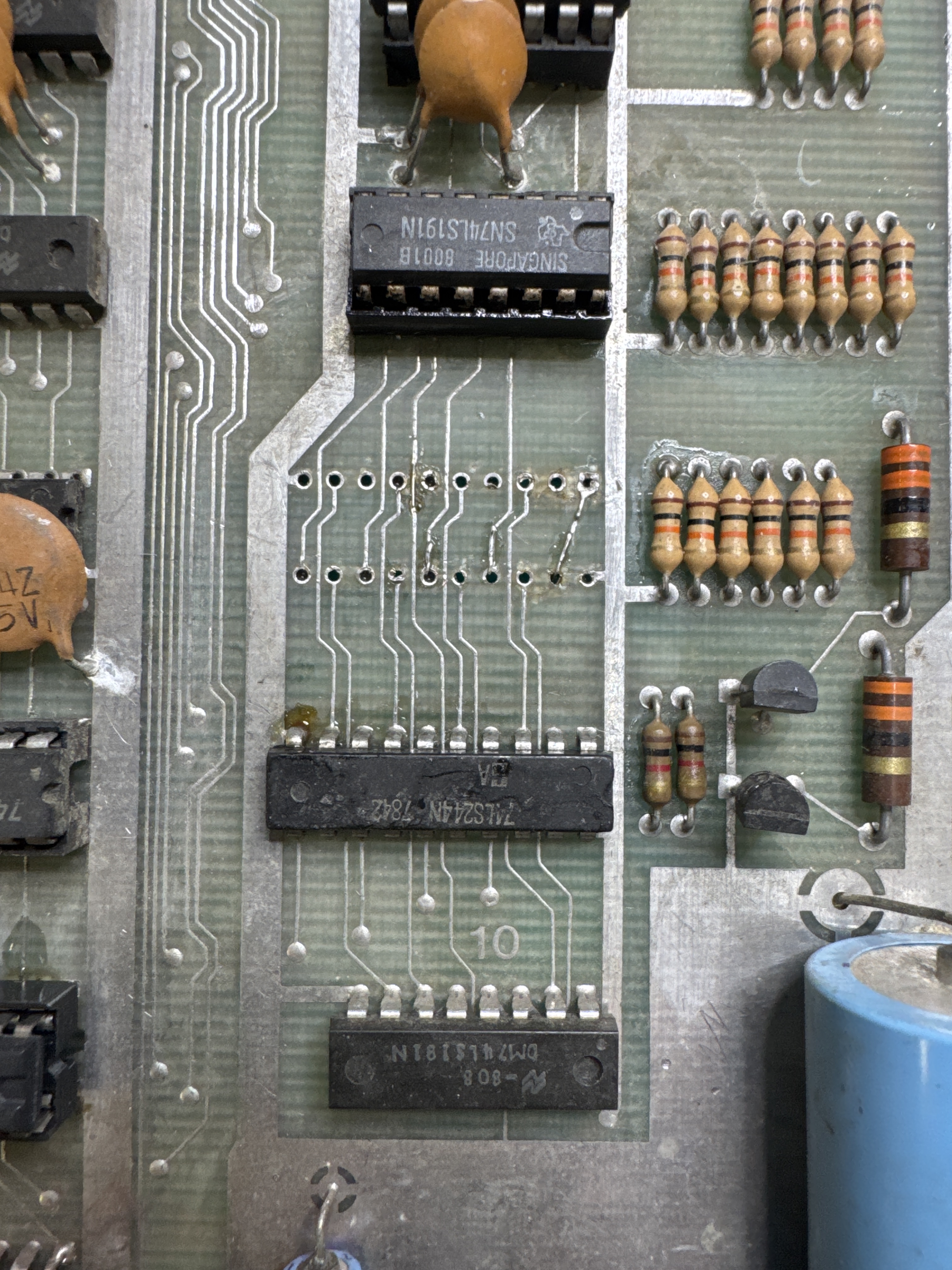
The chip @1B turned into a bit of a treasure hunt. Turns out there are two variants of this PCB. This version has this chip here. The DOCUMENTED version has a 74LS244 at this spot. Took a little to hunt down.. I looked at PCBs of the era and thought it was likely a 74LS157. Putting a socket here and replacing it partially worked, but I still had some RAM errors. After asking on KLOV. We crowdsourced the answer and it was a 74LS157. I keep looking and found the source of the memory issue.
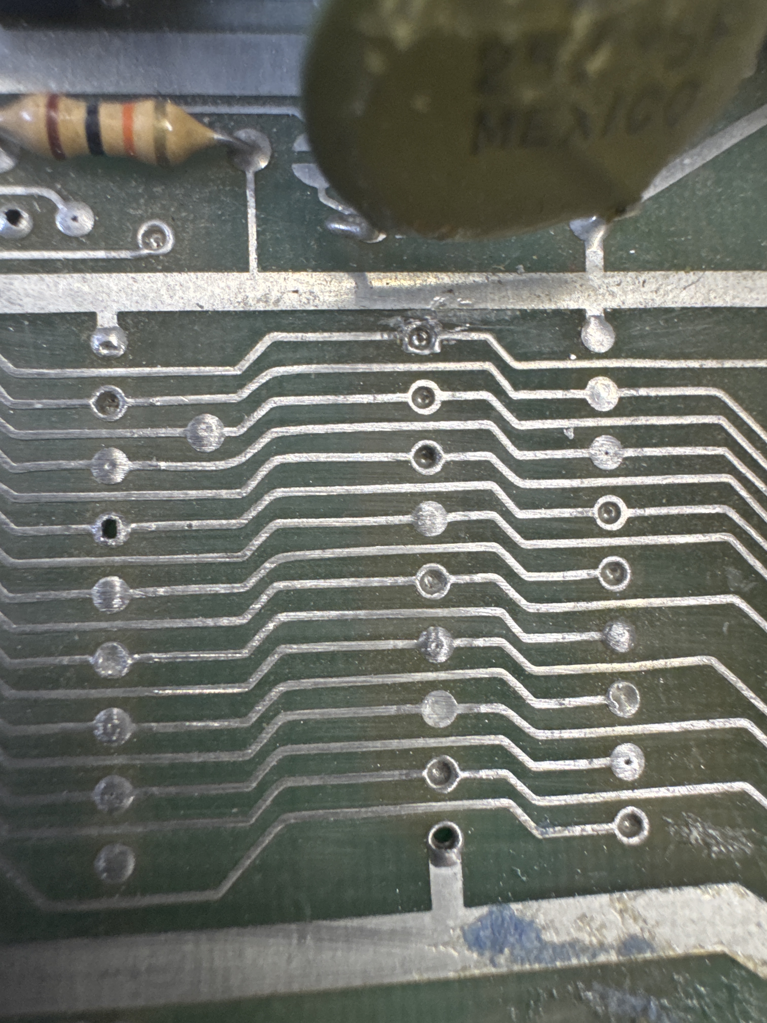
Hiding under this cap when it was bent forward was a short on the address bus. After clearing it, we got to 2 bad RAM. Replaced them.
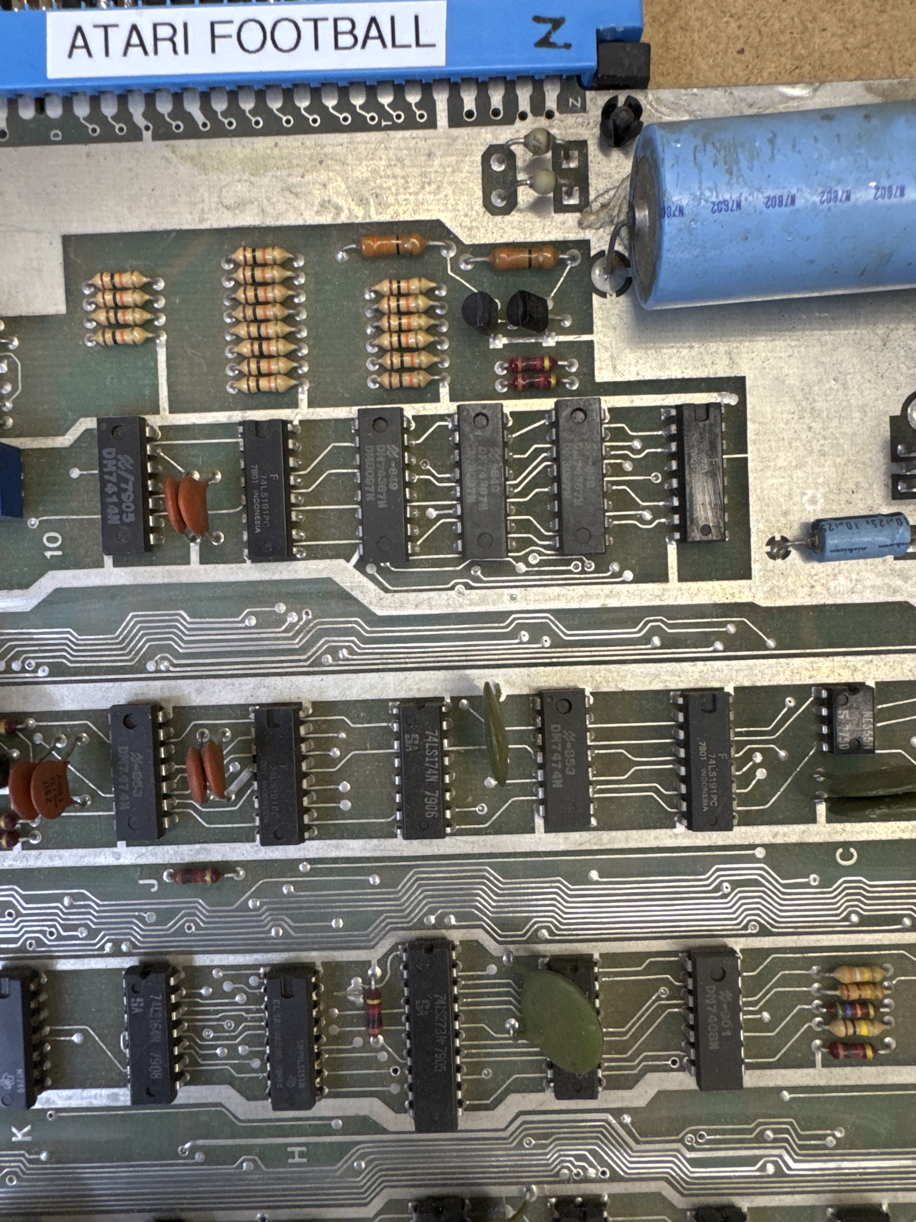
BTW – these chips in rom 10 are nearly all different and not documented in schematics either.
Once I got past all of that, I got this on the screen.. bad vertical counter. replacing it restored the playfield. At that point the game was twitchy and using the trackball caused all sorts of issues. I followed this around for a while – but missed a pin-to-pin short on the back of the board.. Cut the pins and all set. Added a heat sink to the audio AMP. The original AMP is hard to replace and this board was missing it.
Replaced the CPU and ROMs of course.
Board works!
