
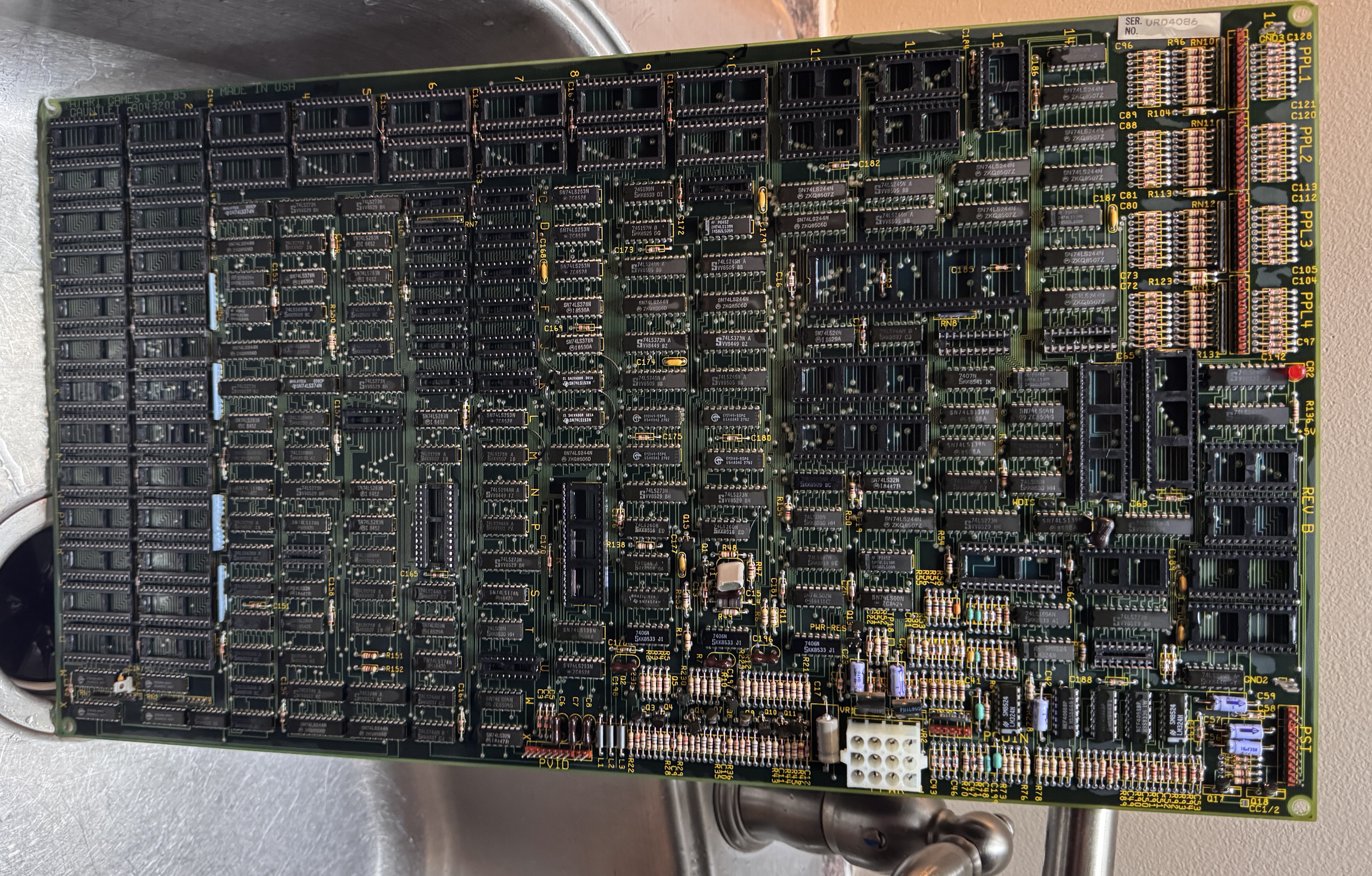
I was fortunate to get a request to repair 3 Gauntlet boards for an arcade. To date I’ve only dipped my toes into System 1 and 2 boards just a little since I have no reference boards and there are a number of custom chips that can be problematic to diagnose. But give me 3 broken boards and I can likely make 3 working ones since they all won’t die the same way. A single board is much tougher since I can’t cross check. Once you’ve repaired a number of the same board, a reference board becomes less necessary.
Power to the PCB as it turns out – I had already created a connector for a Marble Madness – same power connection.
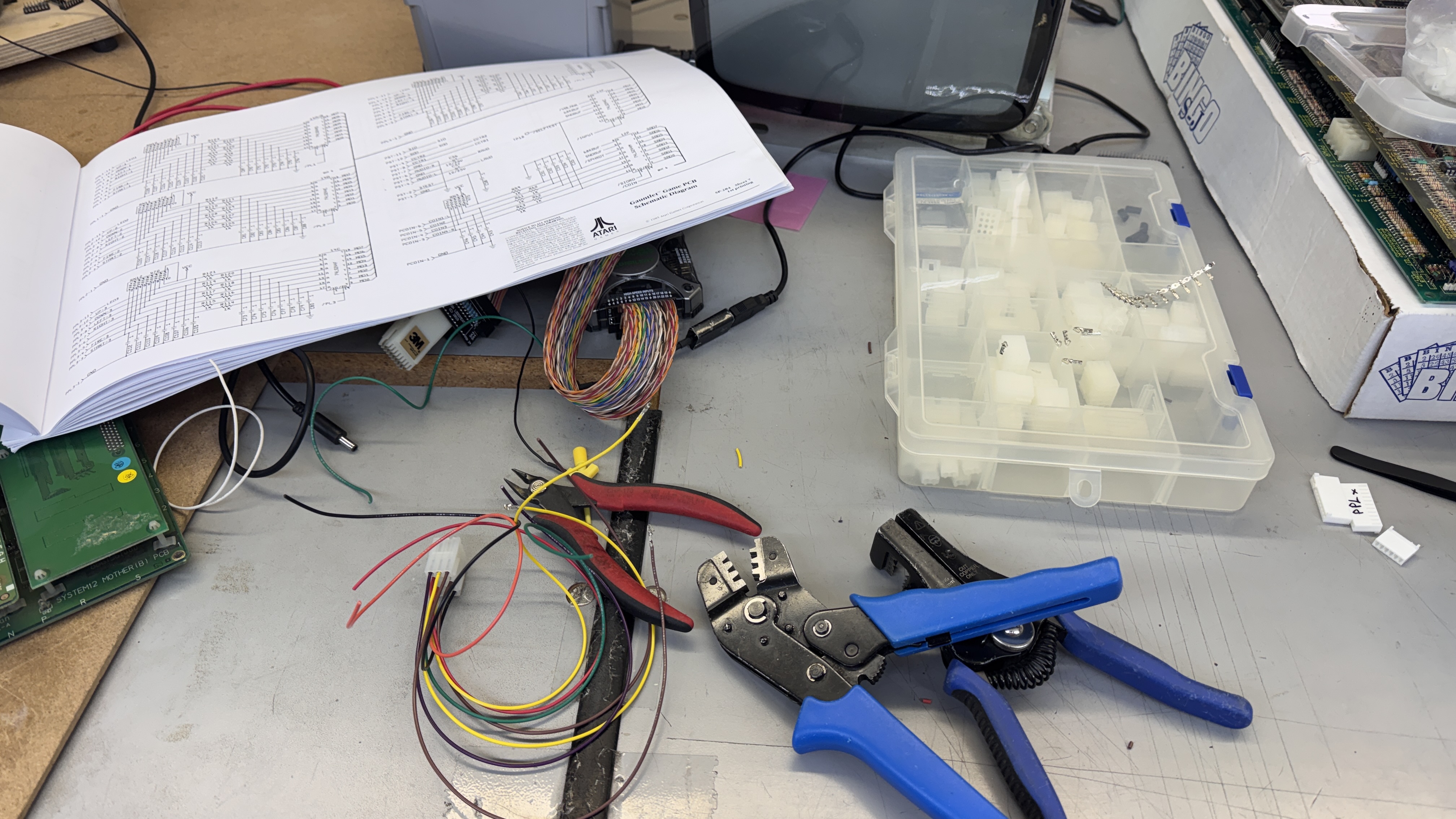
However – the controls for Gauntlet are very different. I made up bench adapters for controls and video. It will connect into my Bench Test Rig and specifically the single joystick controller.
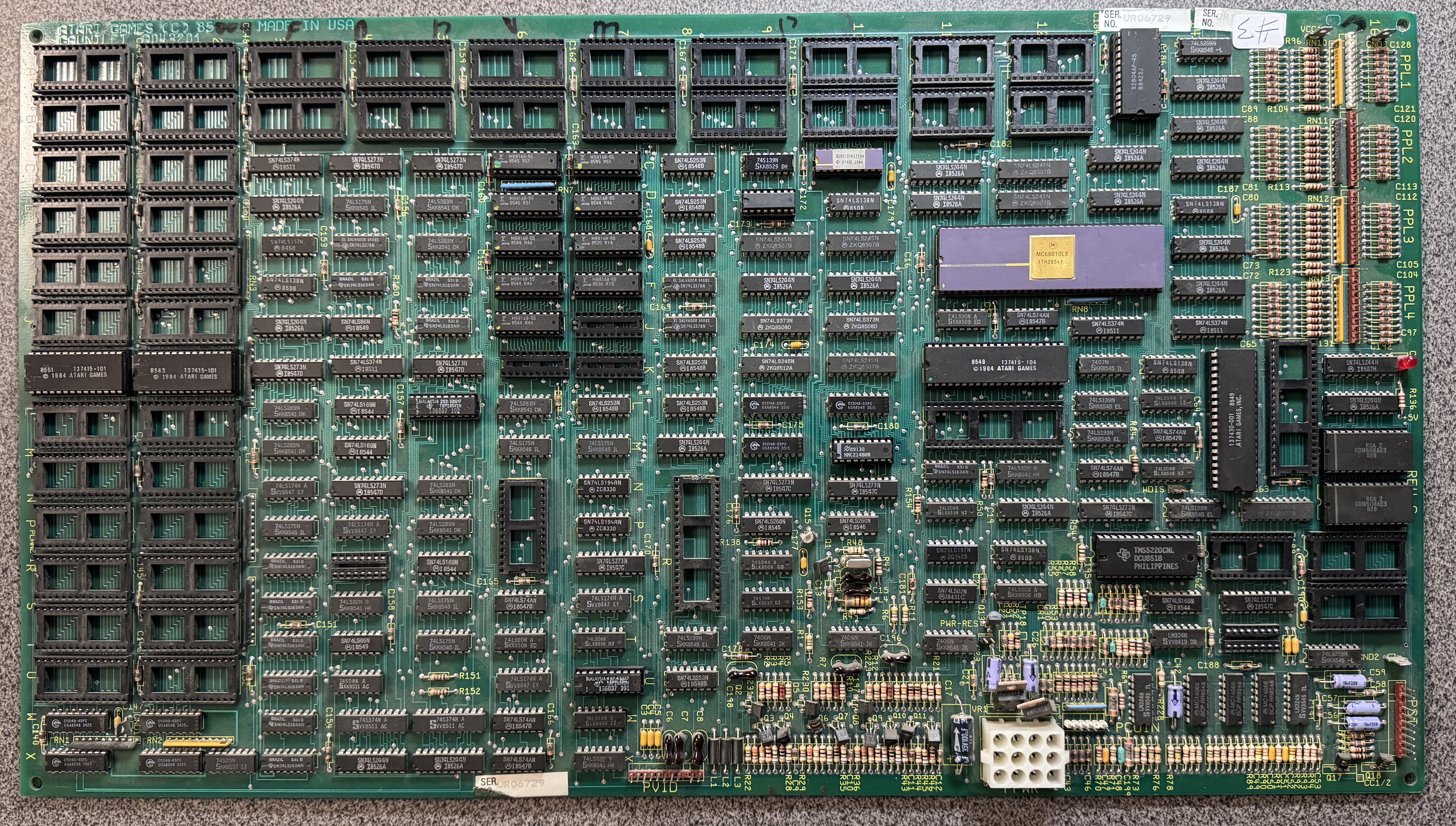
Board #1 – Board in for repair
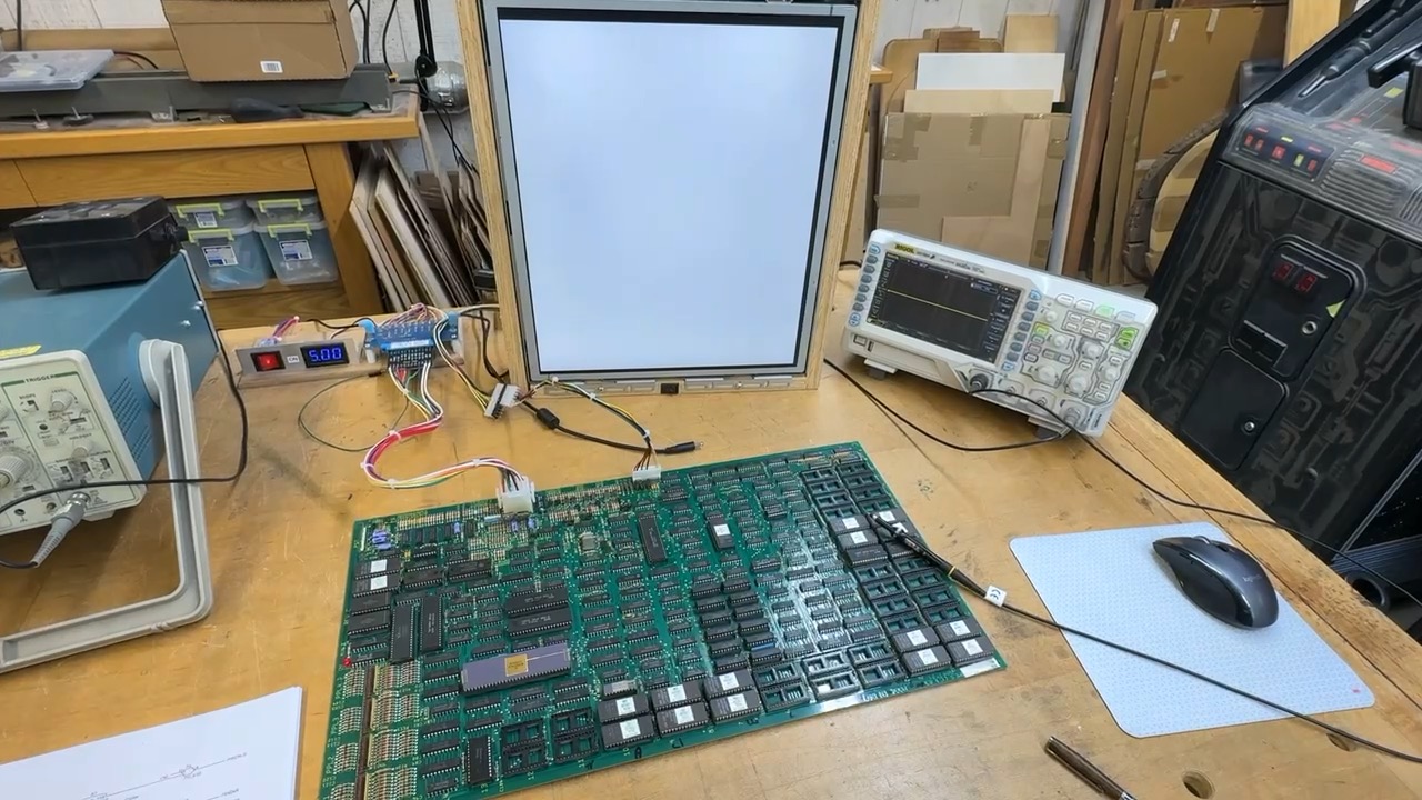
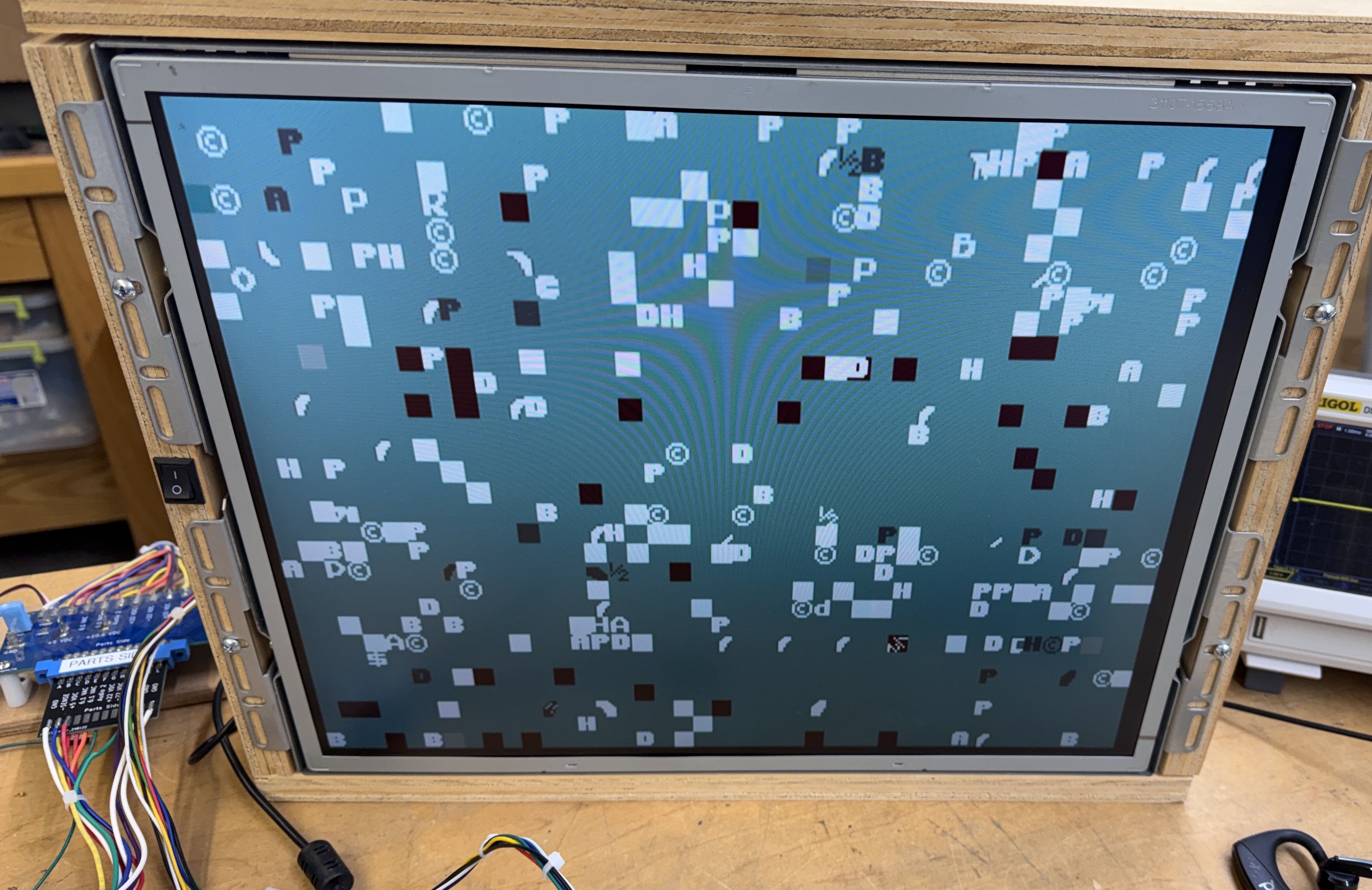
I usually make the video connections first and power things up.. I was greeted with this white screen. Here is where I started swapping socketed chips from board to board just to rule them out early.
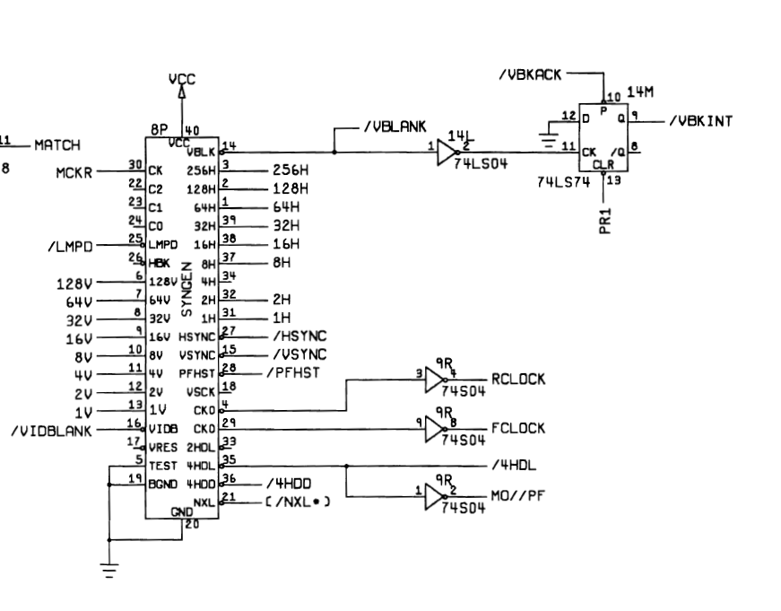
Once I got to here – SYNGEN @8P..
Nice.. At this point I completed wiring the controls, cleaned all the chip legs, etc. and documented the schematics a bit. The are really detailed – but they don’t exactly tell you what each page does like other schematics. That said – the last pages of the schematic have a very good signal name glossary which helps narrow in on what’s what.
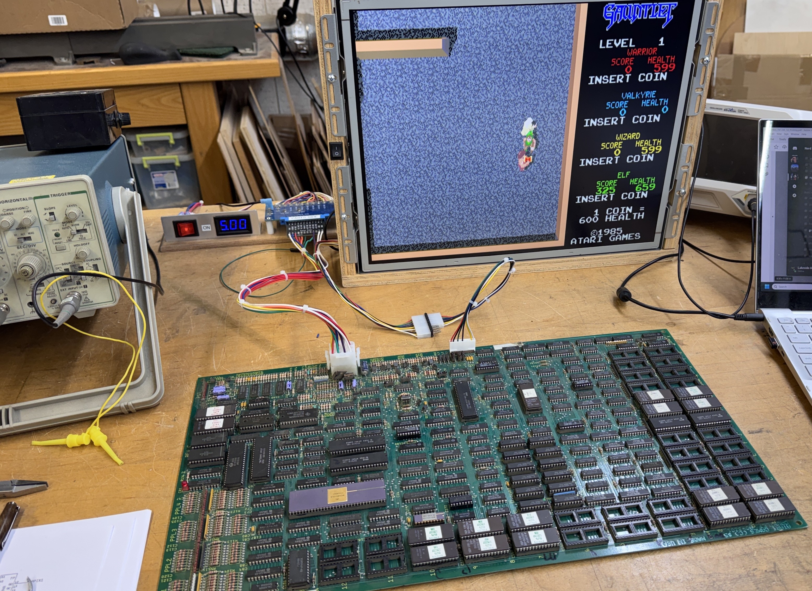
Board works!
Board #2 – Board in for repair
After swapping a few chips around to fill in the blanks. This Gauntlet booted too … Dead.
Inspecting the board…
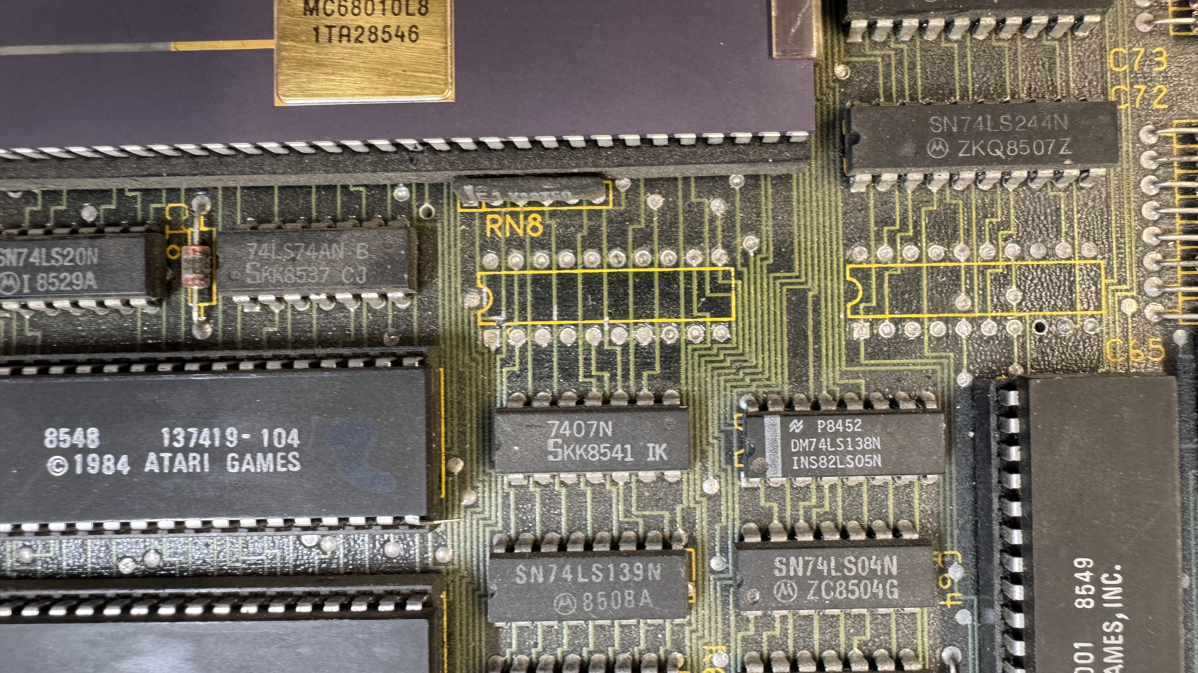
Someone had removed 2 x 74LS374’s @13J, 14J – the board had minor heat damage on the bottom because it appears hot air was used vs. desoldering equipment to remvoe them. Who does that?
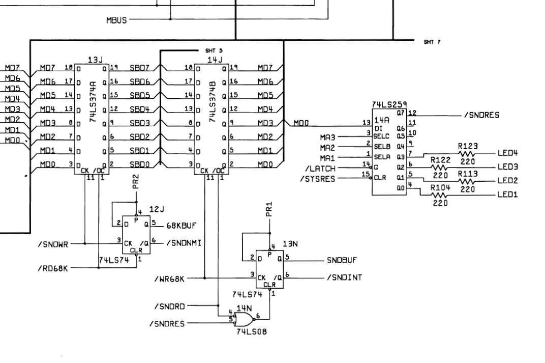
Clearly they are used as part of the sound CPU (6502A) based on the clock and enable signals. I cleaned up and installed replacements.
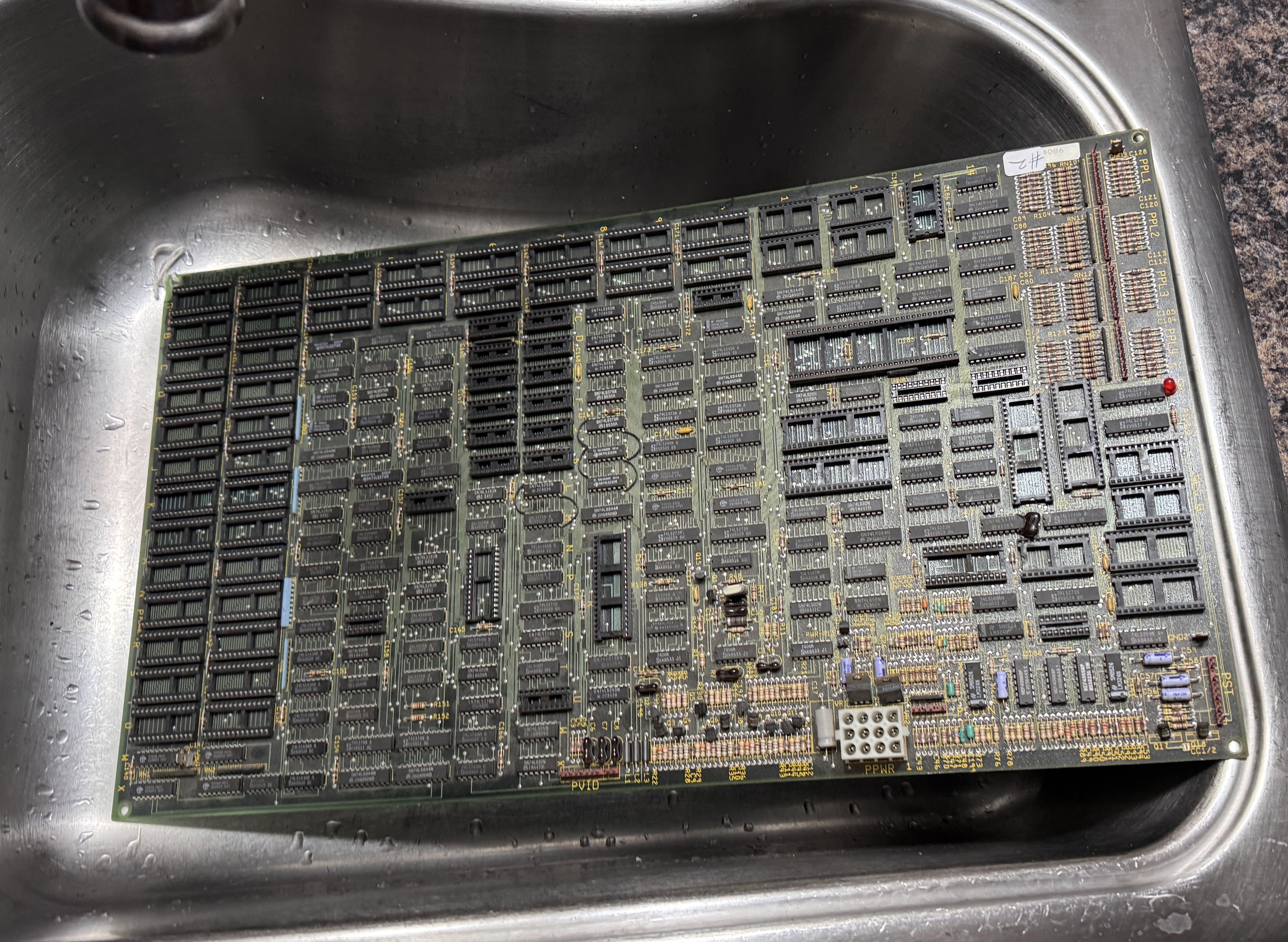
The board itself was pretty dirty and all of the socketed chips were crunchy when you flexed it. So it got a bath..
Much nicer and easier to work on.. After repopulating – it was watchdogging on the 68010. Checking the 6502 – I was looking to see if it was booting / crashing.
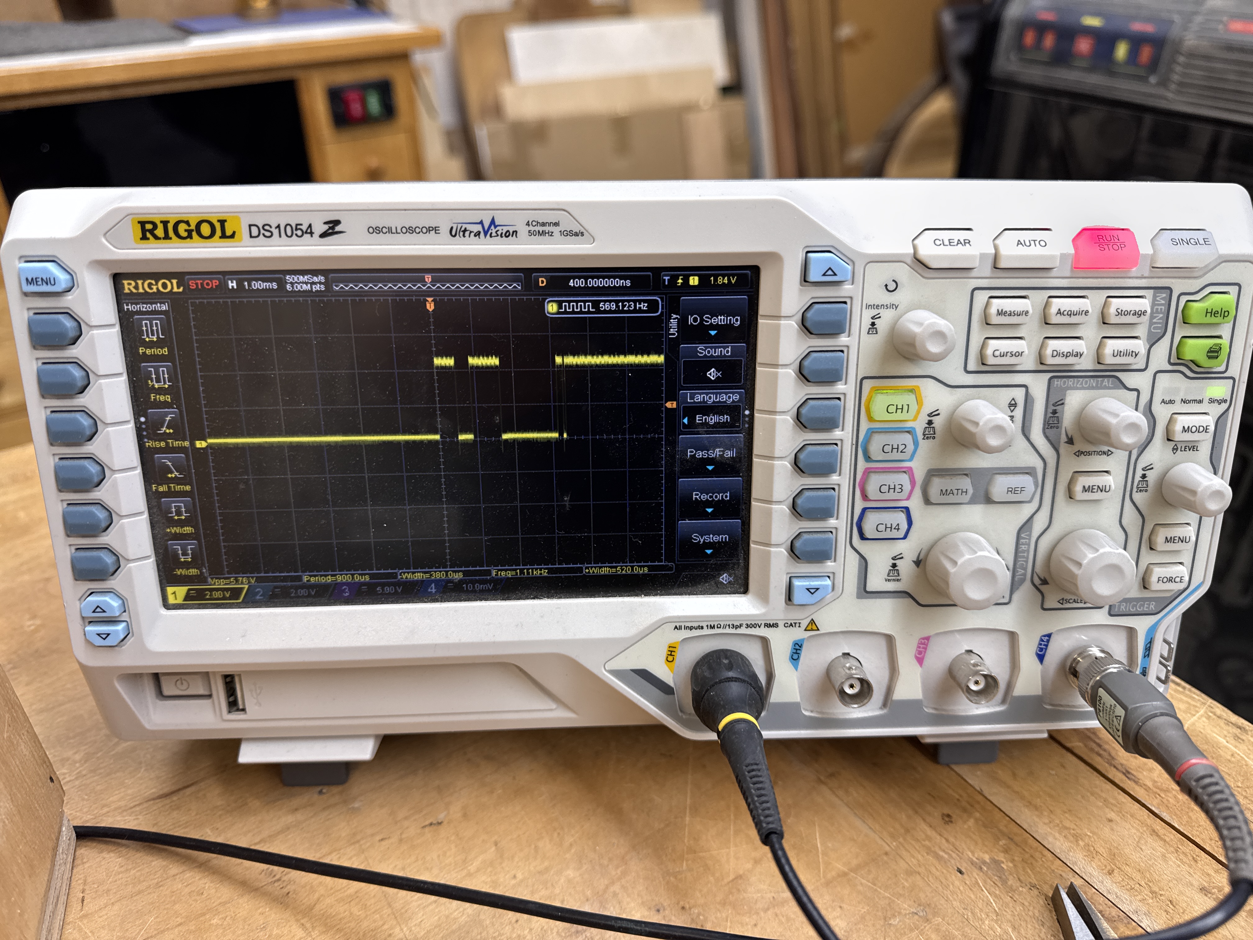
Except this was the reset signal (pin 40). Looking at the schematics and probing around – this made no sense at all. Which means – a short. I followed the reset line on the back of the PCB and found the tiniest little hair of a short. I wasn’t even sure until I swiped it with the soldering iron and it erased.
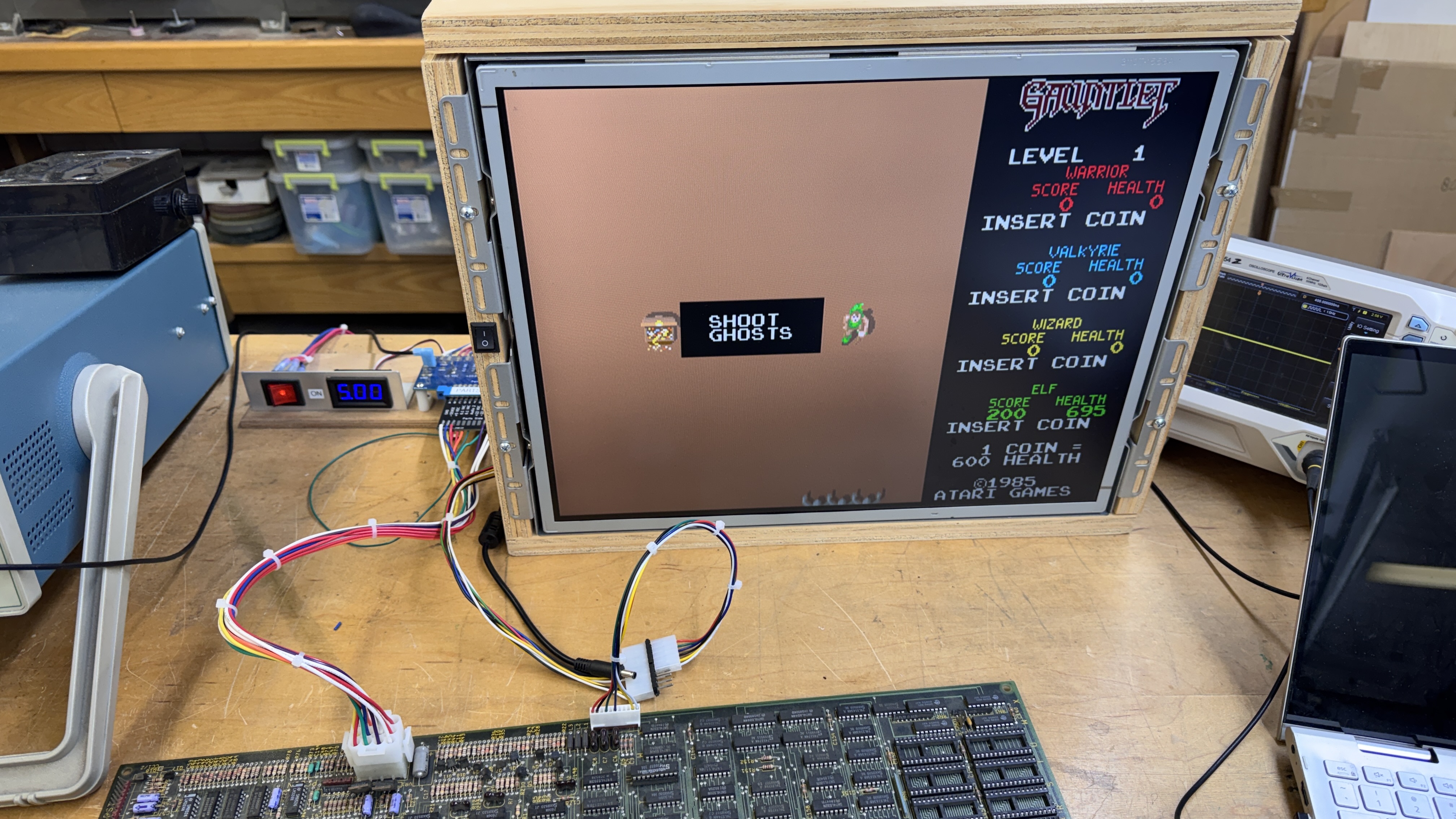
And then it booted! Nice. No background – but I’m not fighting boot issues now. This background color issue was a me error – I swapped 2 PROMs accidentally. The last part was the sounds were all messed up. I searched around a bit and was about to verify the sound ROMs when I noticed – they were original label Gauntlet II sound ROMs that found their way to this board. Burned a new set.
Notice the connections for controls.. The Molex KK .10 connectors are a bit more fiddly to work with than the .156 connectors.. I’m just getting used to wiring them up as most of the other boards I work on don’t use the smaller sized connectors.
Board works!
Board #3 – Board in for repair
This board came in stripped. I was asked to restore it back to full operation. Before ordering any parts – I wanted to see if it worked and what state it was in.. It began by depopulating board#2 and filling this one up.
Here is were it started – needed all of these parts to fill in all the holes
EPROM 27128 – Qty 4
EPROM 27256 – Qty 12
Yamaha YM2151 @15R -Qty 1
Yamaha YM3012 @15S – Qty 1
Atari Custom 137419-101 @12L/M – Qty 1
Atari Custom 137419-103 @8R – Qty 1
PROM 136037-103 @4R – Qty 1
RAM MB8168-55/IMS1420L – Qty 3
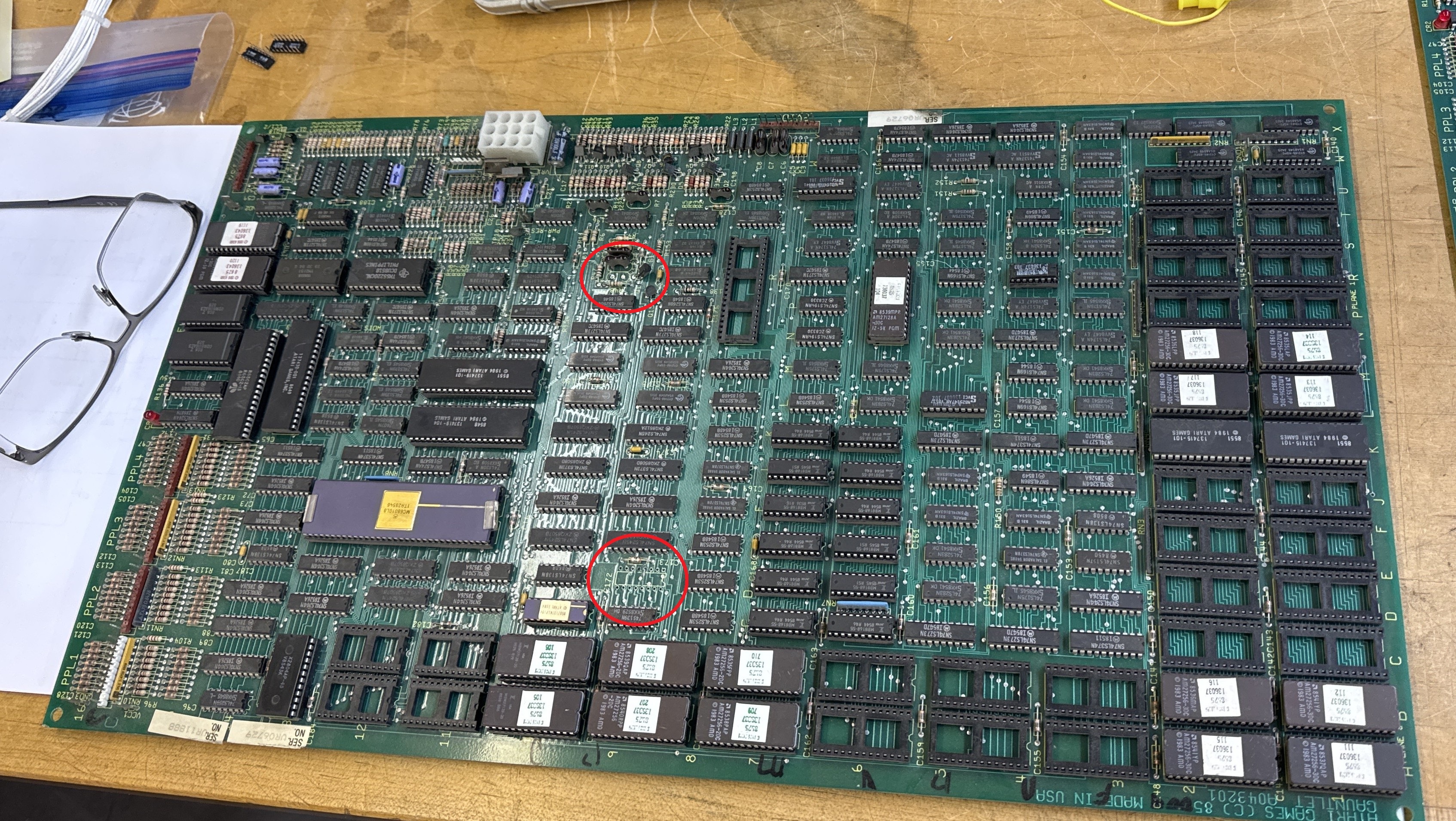
See the red circles? One was an 74LS157@9D. Missing with a couple of pulled traces.. I noticed it while populating the board with parts from Board#2. Seems like a random part to pull and then abandon the entire board. Crystal was also missing. That said – once I got everything together..
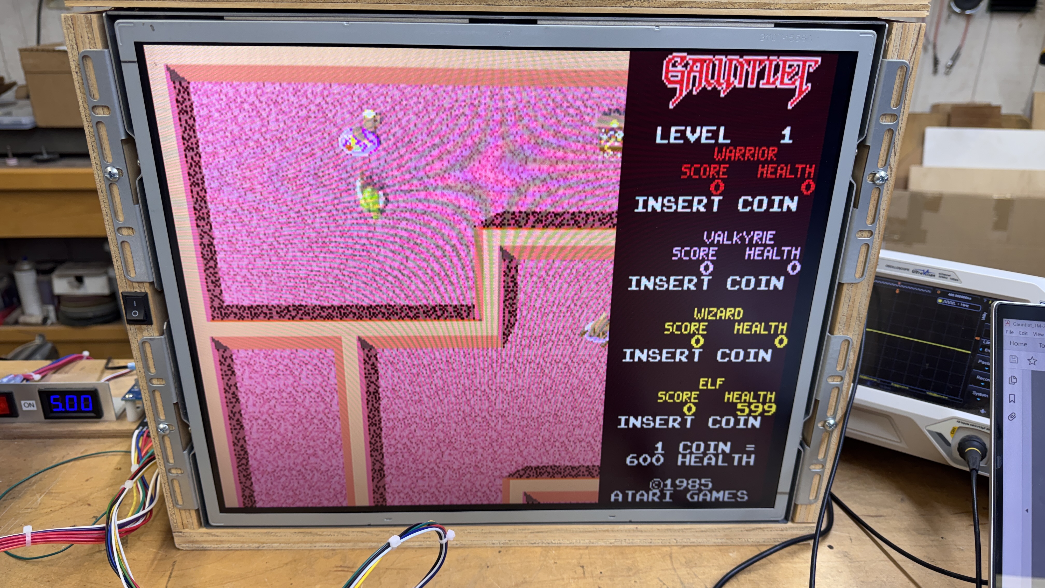
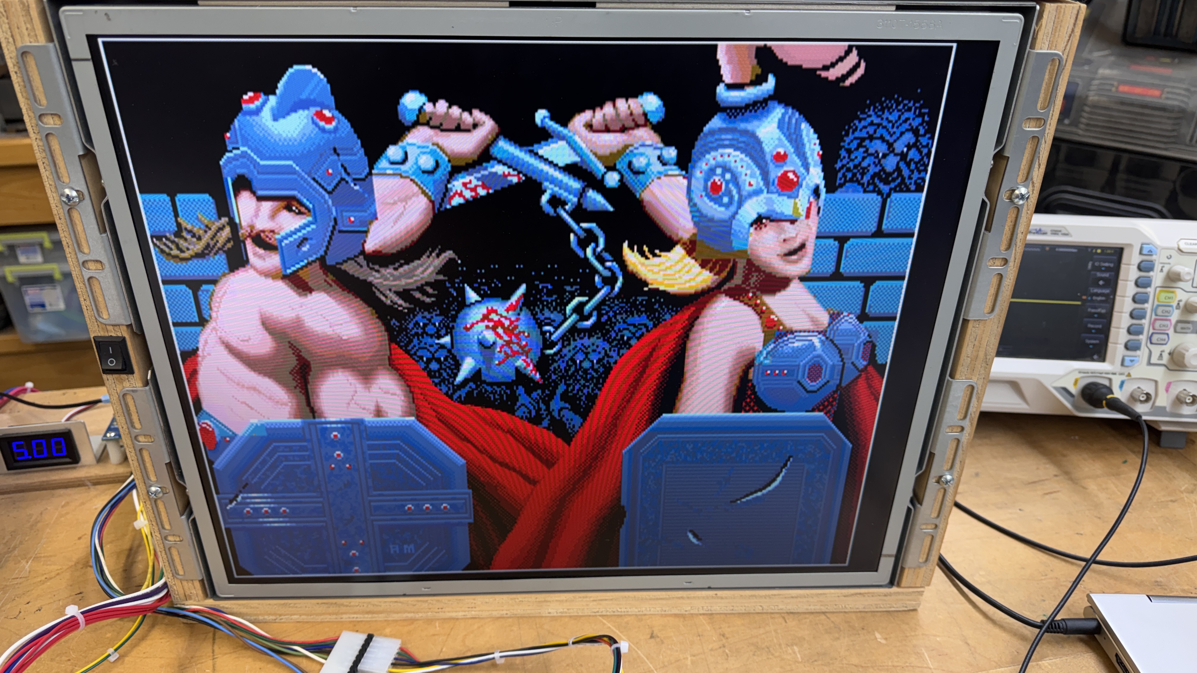
I was greeted with pink.. Was it going to be this easy?
The 2149 RAM@10M seemed like a great place to start. A quick piggyback as a check and the colors corrected. At this point I figured it was a viable board and started ordering parts. They took a couple weeks to show up so I set this all aside. Once I got all of the ROMs burned and the chips installed.
I was greeted with the background being a mess. Something else failed after this board not being powered up all that long.
*** Placeholder for background images ***
Here I probed around the board until I determined what section was involved.
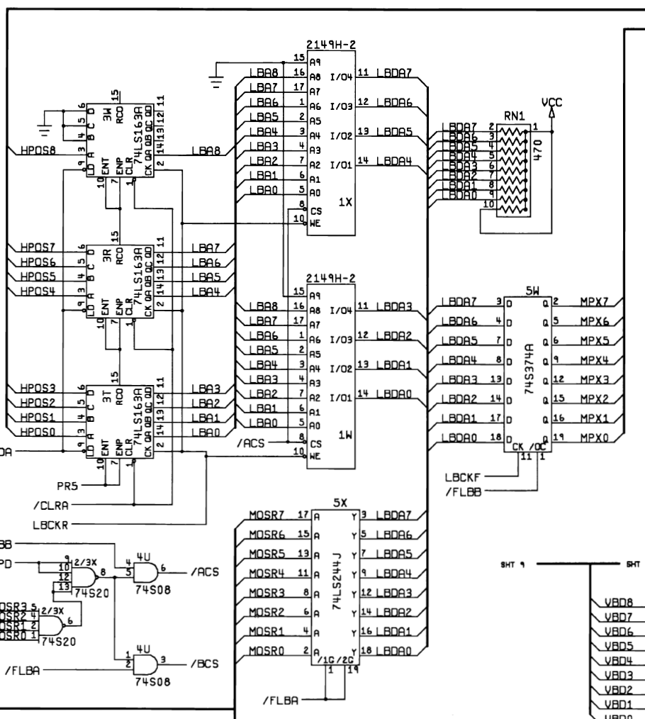
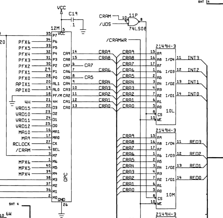
This area of the board is where I was found this issue:
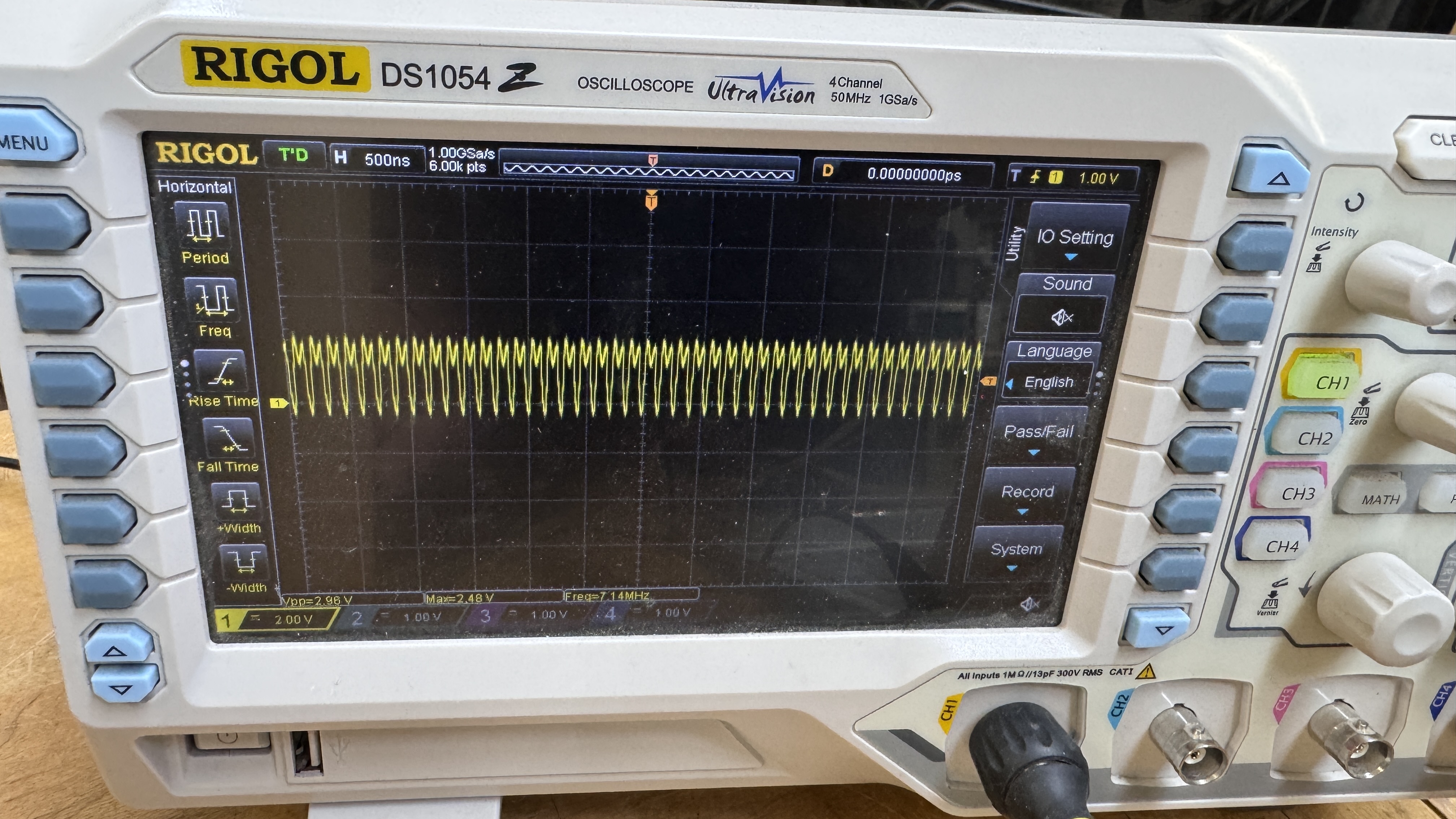
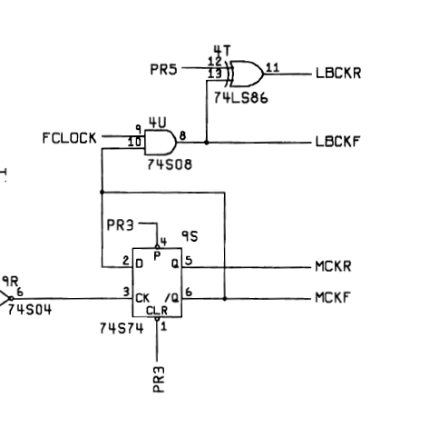
The LBCKR clock – which connects to about 10 chips was being dragged down by something that failed. It’s only 2.4v here. The signal is generated by 74LS86@4T. That particular chip was a Signetics – so I pulled it out. It wasn’t the problem – but it confirmed the issue was down stream for sure.
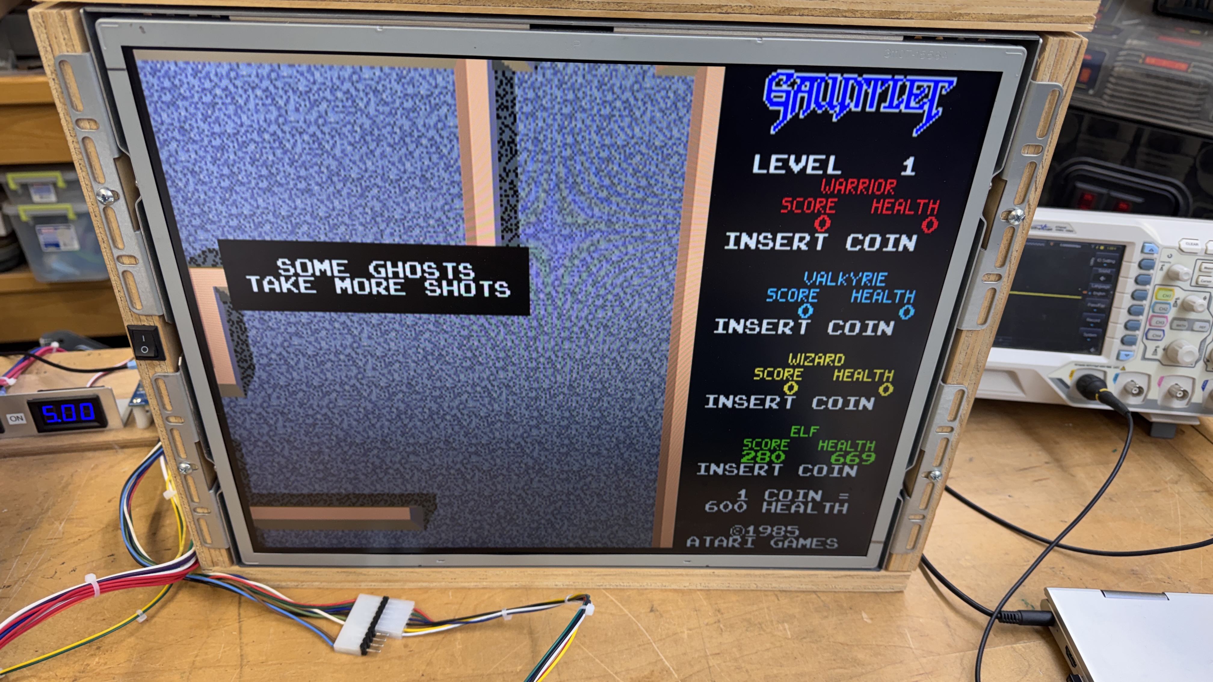
All of the colors were restored. Just the motion objects were missing. Of the remaining chips – 6 were 74LS163 counters (Texas Instruments) and 4 were 2149 RAM. I don’t own a FLIR thermal camera – but the case has been made yet again that I should look into buying one. I used a laser thermometer and checked all of the chips in question. 2149@1W was the warmest of all by just a couple of degrees. Removing it cleared the clock being dragged down. Replacing it produced this:
Motion objects with lines.. The 2149@1X was also bad. Replacing that fixed the all of the graphics issues. Great!
Somewhere in the middle of all of the testing and swapping, an Atari custom “SLAG” chip failed. It is connected to all of the graphics ROMs and helps generate output. The screen had a very flat look to it.
Connected up the controls and it appears the 6502 is only partially working – no controls. Swapping that out got me controls and audio. Working 100% right?.. wrong. Board would not go into diag mode.. I probed around a while and checked signals against a working board. It seemed like it was just stopping in the code.. Swapped some ROMs, nothing. Then I decided to RTFM.
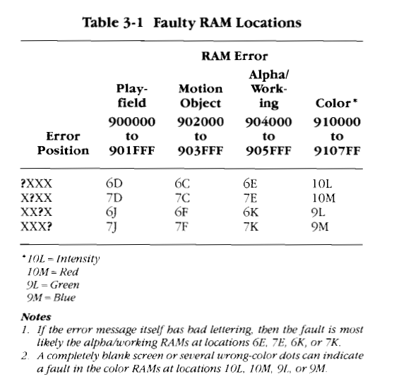
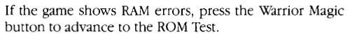
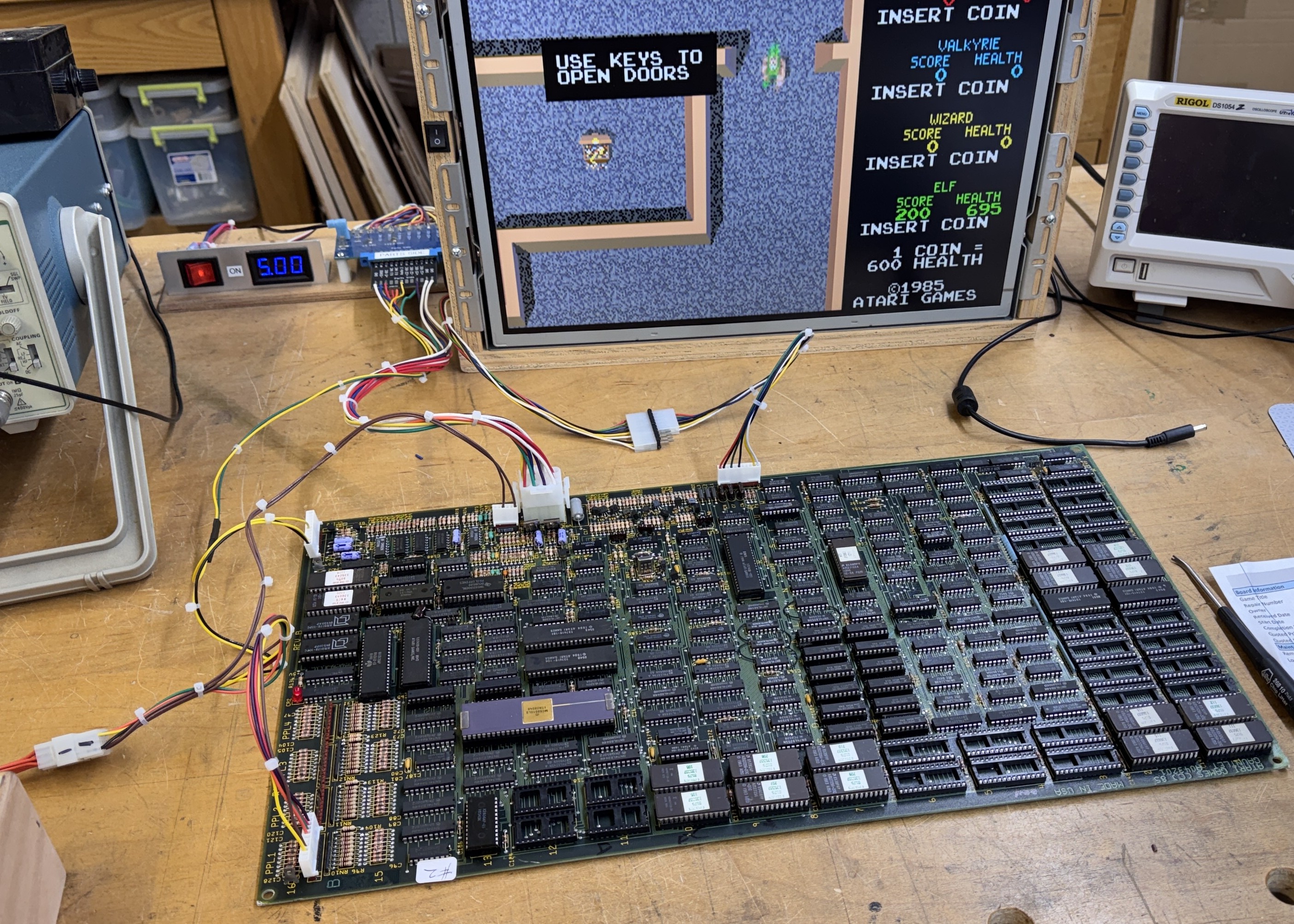
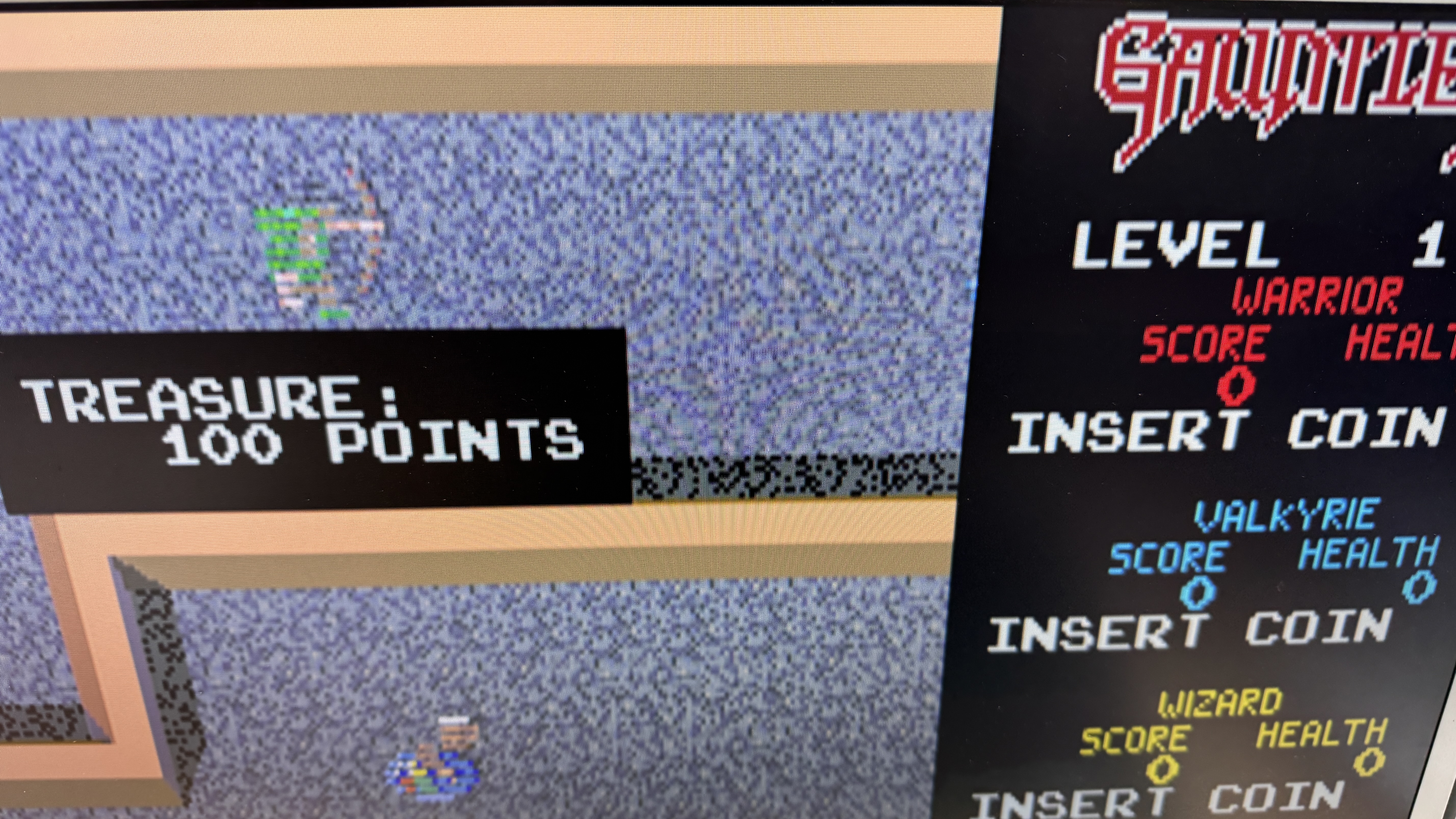
I clipped out the important parts from the manual. A completely blank screen can be a RAM fault. I’ve already had 3 x 2148/49 failures. I piggybacked 2148@9L and got a flashing RAM error screen. Then I hit the Magic button and it continued to the next test. Excellent. Replacing the RAM fixed the issue and got DIAG working correctly. Experience +1. It wasn’t lost in the code, it had just stopped for the memory error that wasn’t visible because of the memory error. They were smart enough to provide a button to advance out from it.
*** Finished ***
Board works!
