
Received my first Lunar Lander repair request – I’m a little surprised I’d not seen one yet.. But happy to get one to work on..
Initially I thought I would be able to reuse my Asteroids bench adapter and make a bench controller adapter to allow for the analog inputs. After looking at the schematics and pinouts I decided I’d make a dedicated Lunar Lander bench adapter. There were too many cross connections that I didn’t want to deal with. Plus, I like making adapters.

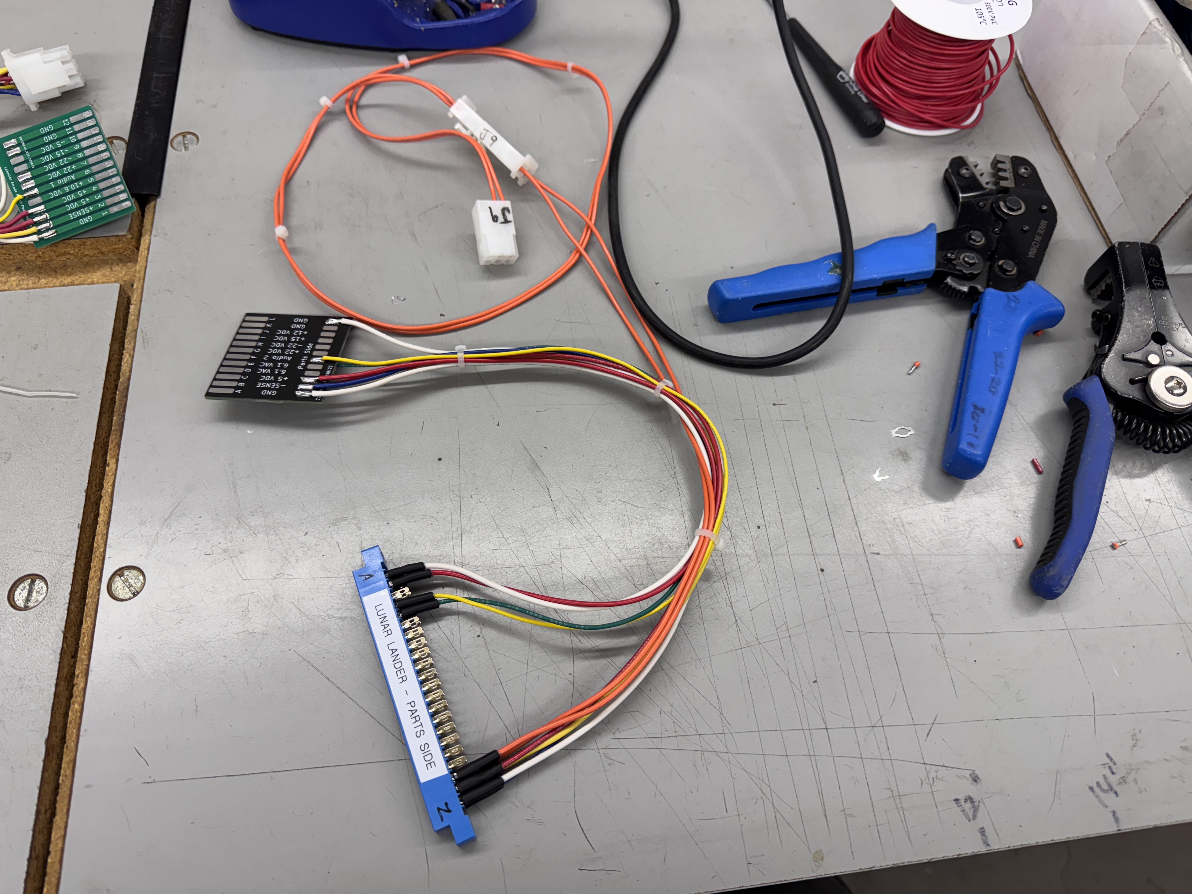
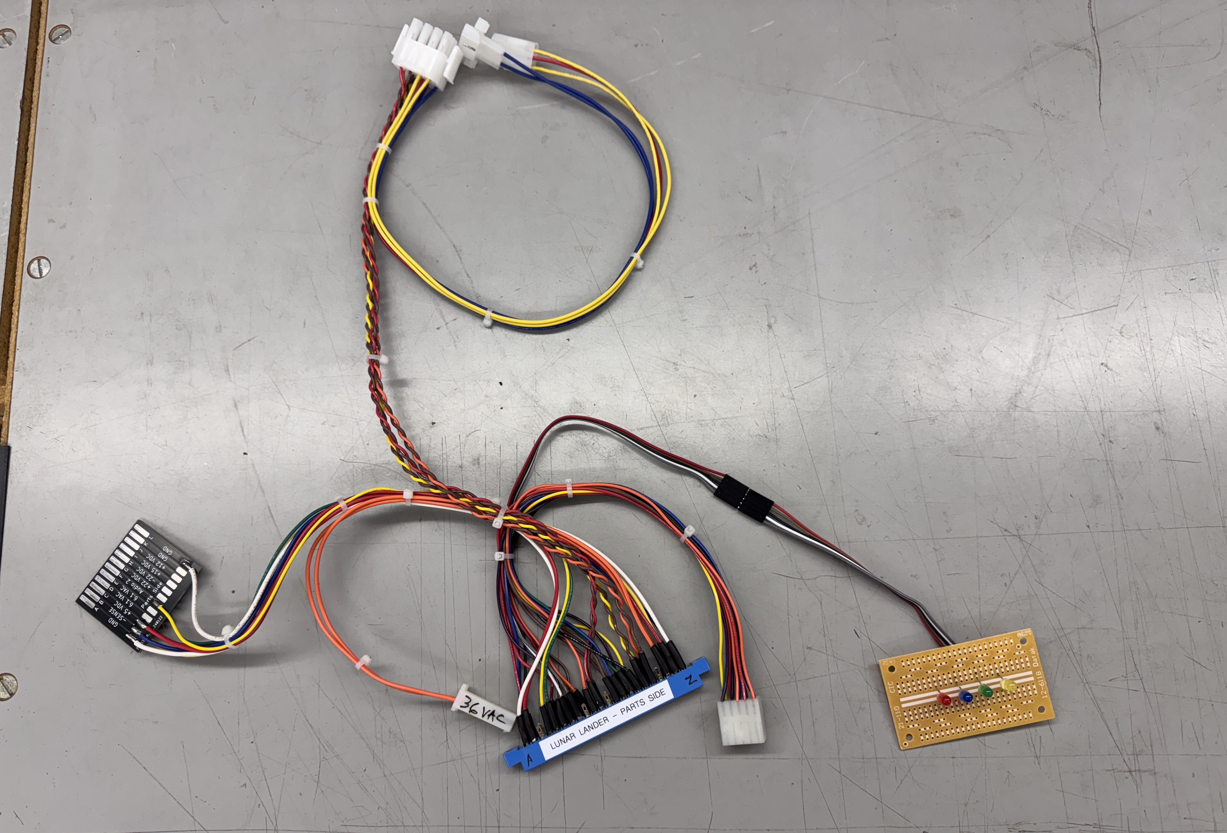
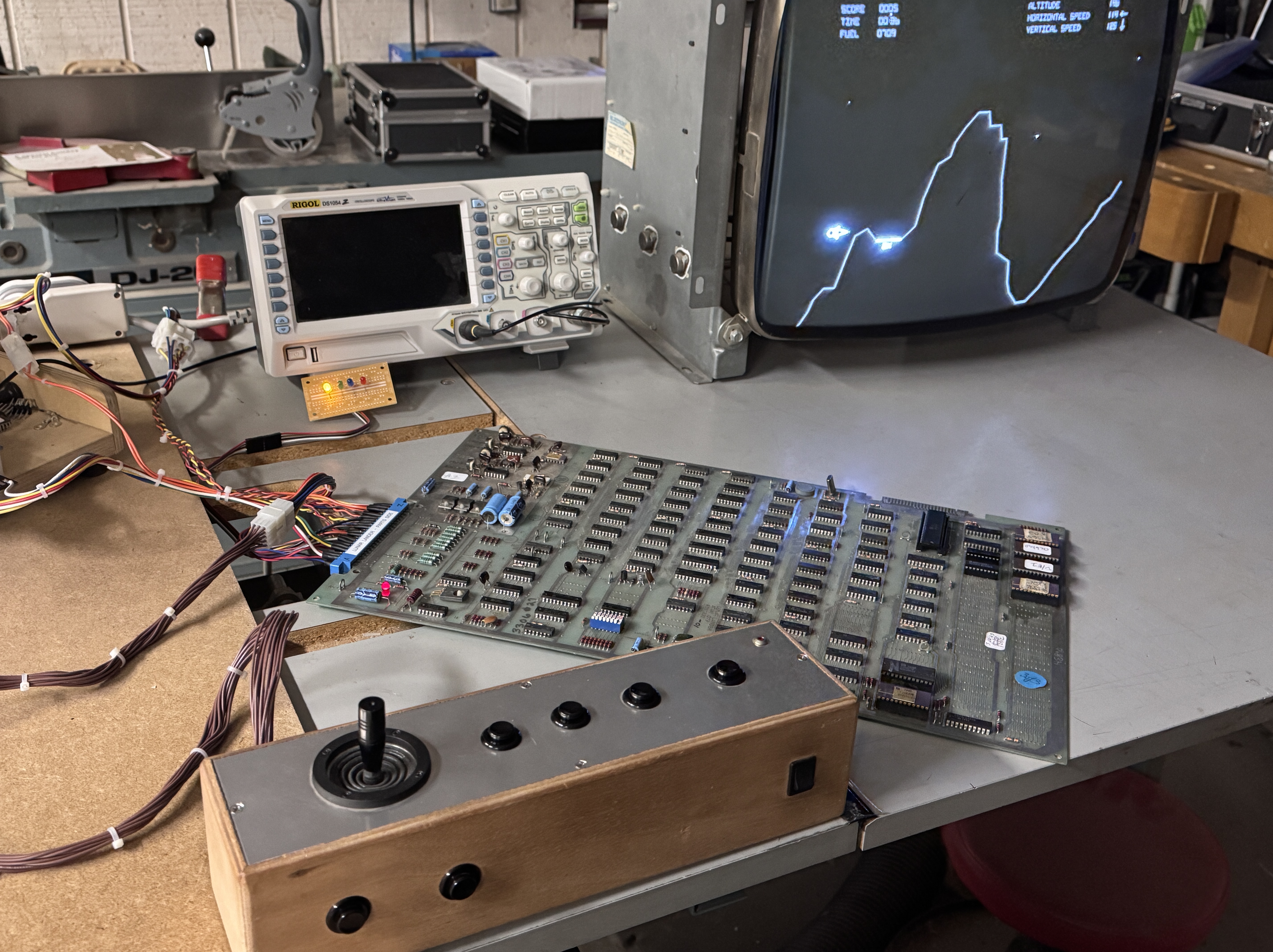
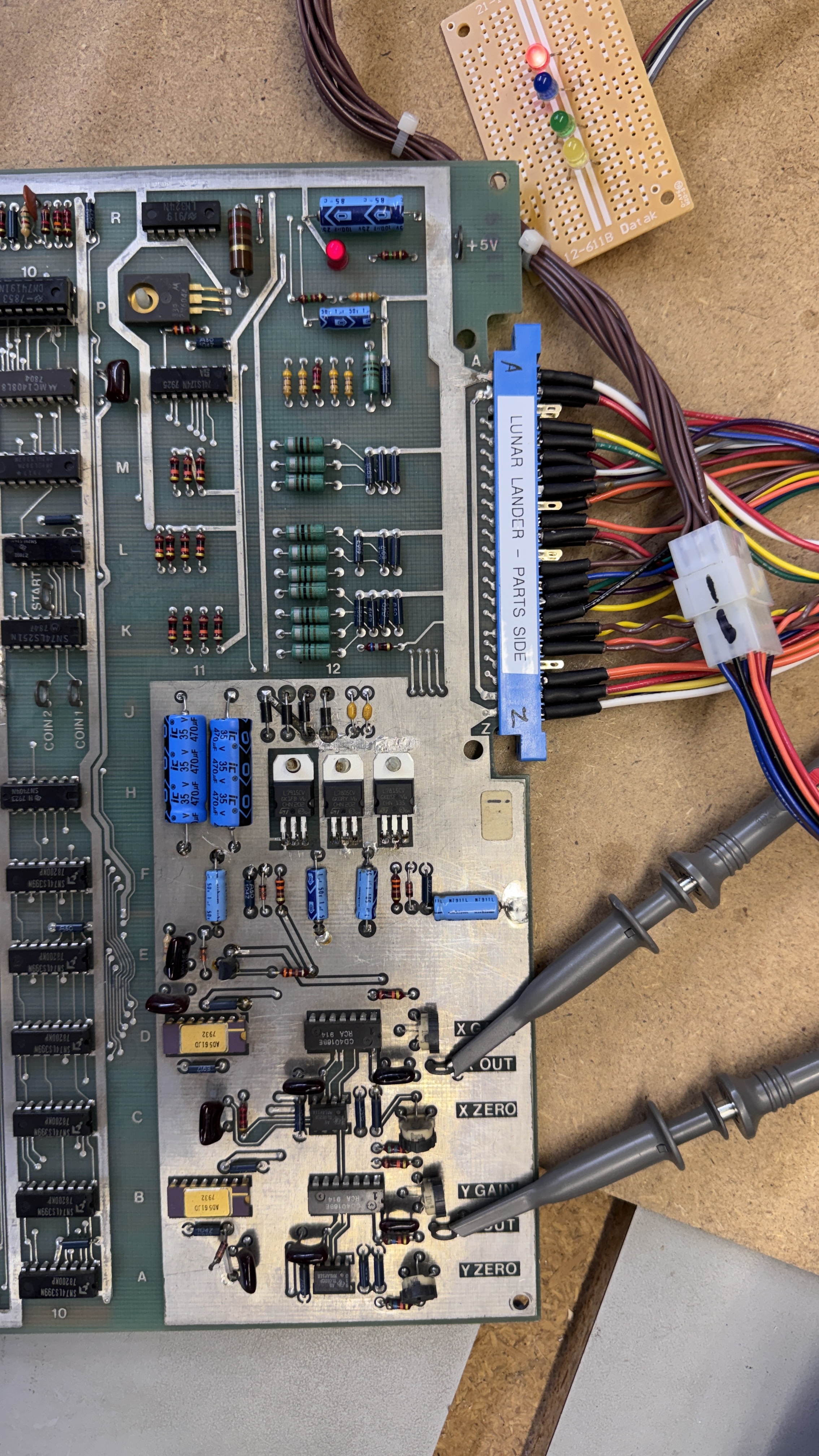
Here it is in various stages of completion. The second pic is my first stopping point. It has all of the power connections to run the PCB. Once the board is repaired – I complete it with controls and monitor connections that are compatible with my Bench Test Rig – which has been a great timesaver long term. However – my adapters can take a 2-4 hours to make depending on the game board. Vector games take longer just because the of the video connections vs 6 wires for a raster game board.
Board #1 – In for repair
Reported Symptoms: Doesn’t work

It is very similar to Asteroids – but definitely not the same. Connecting to power and a scope – the board was watchdogging as expected.
Started with the Asteroids config for the FPGA Tester and started to modify it.. then deleted and started with a clean config and a memory map. Once the RAM and ROMs were set up in the tester..
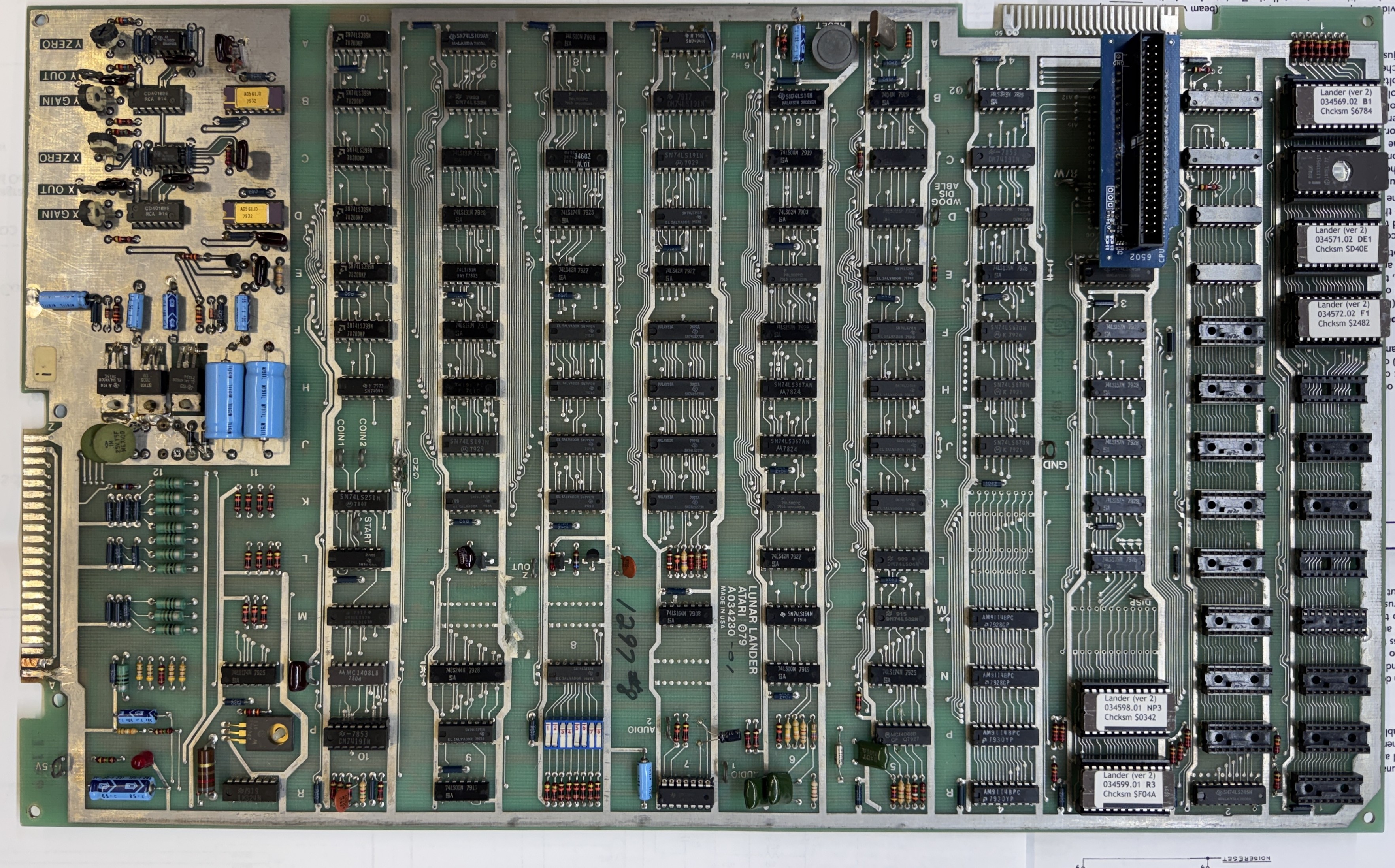
Tester showed a bad ROM@D/E1 and a bad RAM@D2. I pulled the ROM, confirmed it was bad and replaced it. The RAM was a different story. Someone put a 2114 RAM in @D2. Lunar Lander uses a relatively rare RAM at this location – a 2111. I’ve never had to replace one (or bumped into one actually) and had to order it. Once it arrived – they shipped 2114’s by accident. It was quickly resolved and the correct RAM was shipped – but I had to wait another few days for it to arrive. So I set it all aside.

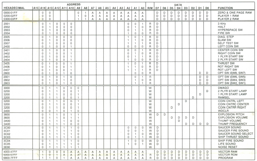
This is the Lunar Lander memory map from the schematics.
For reference – here is the Asteroids memory map. I did refer back and forth a few times as I was working on the config file for the tester. The two key items were page zero RAM (the 2111 RAM chips) and the HALT address were different. DMAGO/VGGO and DMACNT/VGRST are the same – after some cross checking..

Here is the config I started with based on the info I had.
Once the RAM arrived I got all RAM good and ROM good (or so I thought….) I tried to boot the game and it was still watchdogging. At this point I went through the vector generator tests with the tester and the board would run any given test only once. I would then get a HALT timeout error. One of the tests puts the diagonal test grid on the scope. I could make it happen once per click. No repeats and changing the VGGO count had no effect. All of the tests ran once and the commands that used the VG drawshort instruction had timings ~1/2 of the standard drawshort times for the Digital Vector Generator.
From this point forward – there was a lot of learning going on.. partially based on one little item I missed and mostly based on getting a much better understanding of the tool. One thing that was keeping me off balance was the drawshort not being right.. I spent some time poking around the entire circuit looking for why I could only run a single test and it would timeout. I followed the HALT around and it was all working. Hmmm… I was done looking at it for the night.
Next day with fresh eyes I poked around a little and noticed my one little item from above..
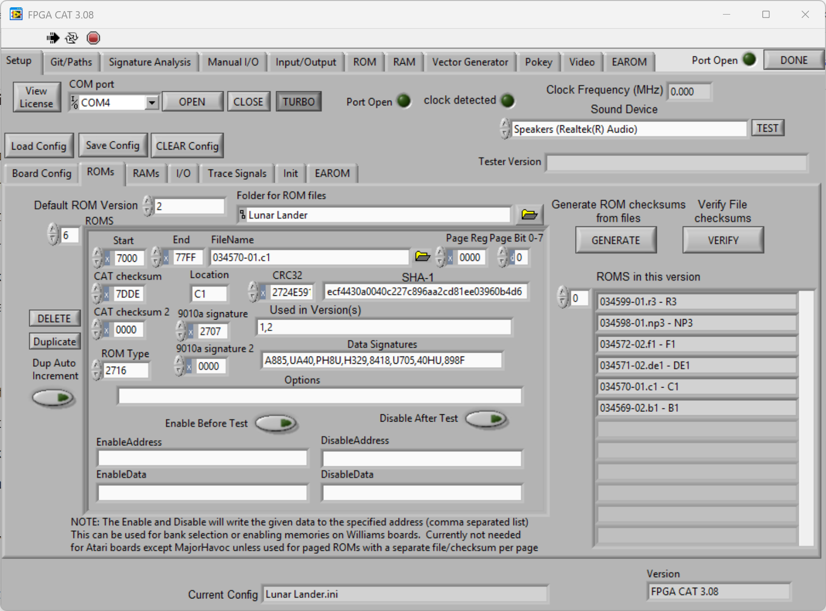
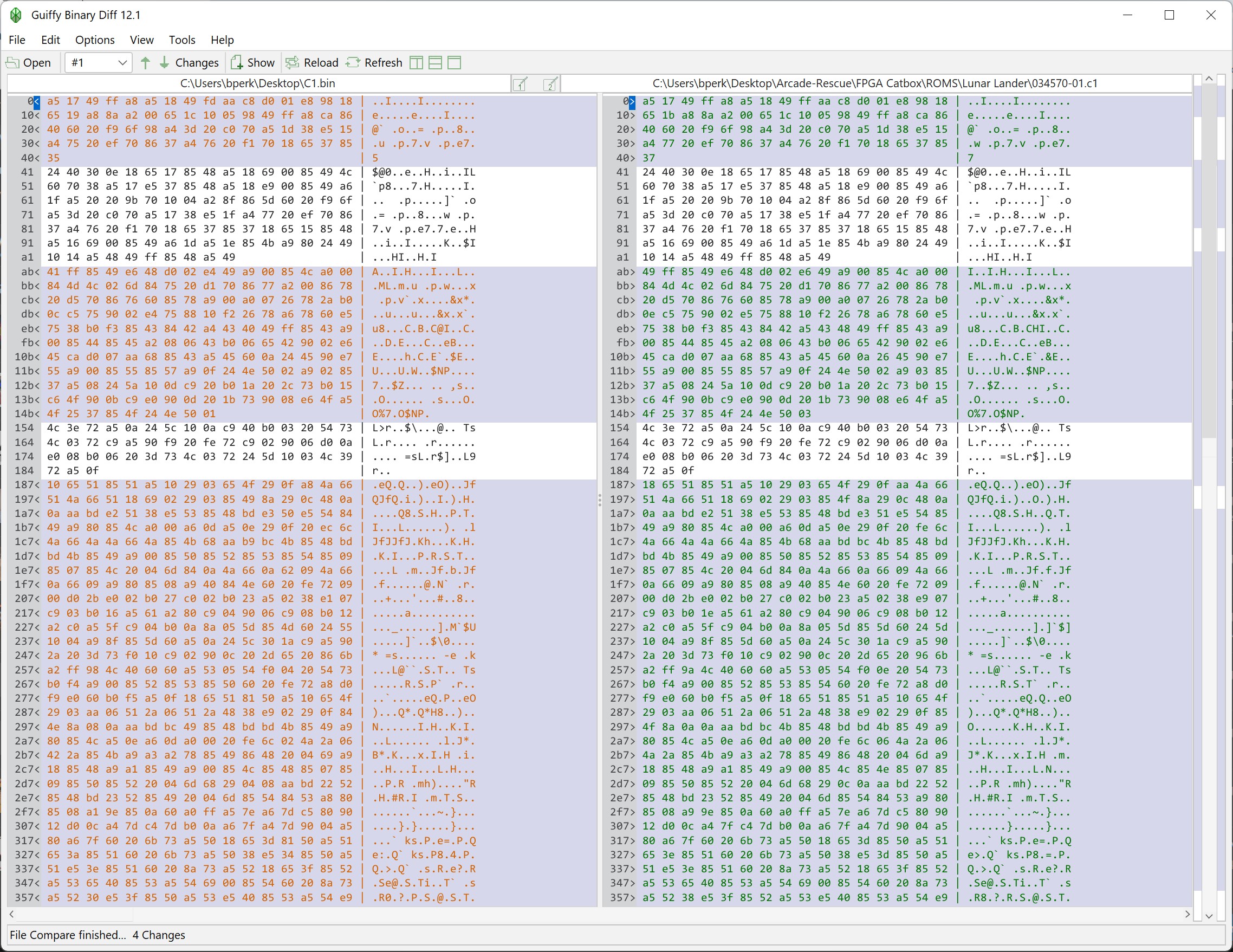
When creating the config file for the ROMs, the ROM@C1 is in both the V1 and V2 romset. I missed adding it to “Used in Versions(s)” as both. I just had it as V1 and I was only testing 5 of the 6 ROMs in this V2 romset. Once I added it to the test – ROM@C1 was bad.. checked it at the bench.. it was bad.. burned a replacement. What are the Odds of having 1 of 6 ROMs being bad AND missing it in the test??? For me – 1:1
Now that I had good RAM and ROM – the VG tests still didn’t work – but the board booted and ran the game. GREAT! Now.. why wasn’t the VG test working on a working board?
I’ll tell you..
After it booted and ran it was obvious it was a config issue for the Tester. I focused on the VG settings. I reviewed all of them, but I’ll focus on the trouble makers HALT addr and HALT bit. This is where the inconsistencies started to appear.
Looking at the LL memory map from the schematics:
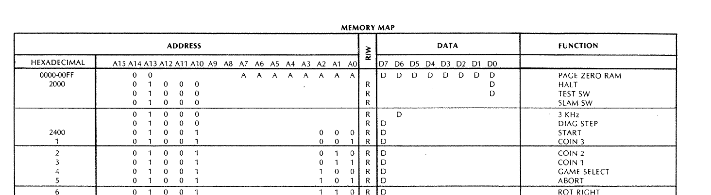
HALT addr = x2000, HALT bit = x0000. Asteroids works at x2002, x0007. I tried that – no difference.

This one was just different. It was part of the clue that something was wrong with the memory maps in general.

This map agreed with the schematics. Interestingly this is from source up on Github. Thankfully I did not stop here… I searched for HALT through the LL source tree.
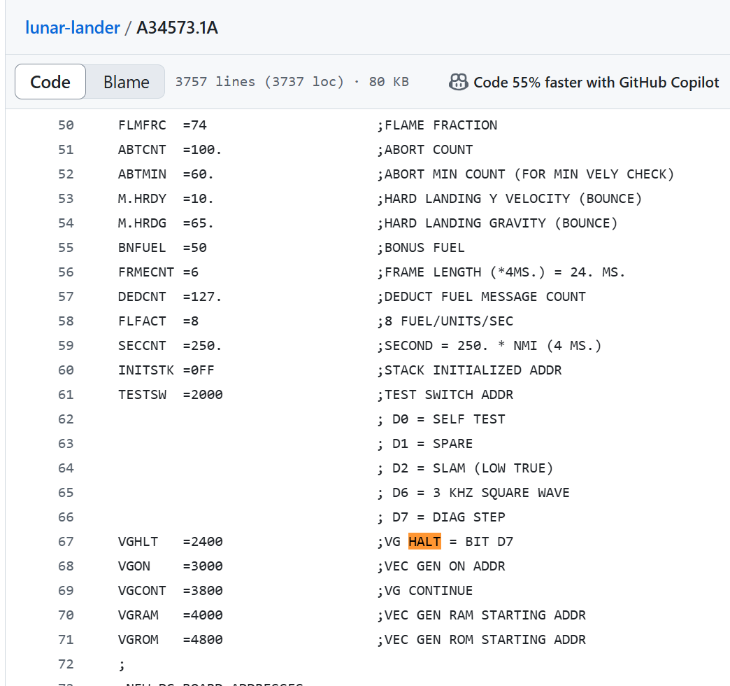
Came across this table in one the LL files.. HALT addr = x2400 and HALT bit = x0007. Added that to the Tester and like magic it all worked as expected! All of this made me realize how the Tester runs the Vector Generator and what it is actually doing..

This window has it all. VG Ram for where the vector code is written to. Size of the RAM so the program can’t go out of range. VGGO which tells the VG to start and run the VG code.. But the tester, just like the actual game code has to watch for the HALT bit to be set to know that the VG has finished executing one pass through the vector program.

Because the tester is clipped to the HALT signal – I figured that was all that was needed.. nope.. that just provides the Neg Pulse Width measurement that shows up in the Tester Vector Generator tab below.

The HALT bit – which needs to be visible on the address bus is actually read from here:

HALT comes in on pin6 of M10 and can be read when /SINP0 is triggered. Makes perfect sense! I’d never really had to think about it before.
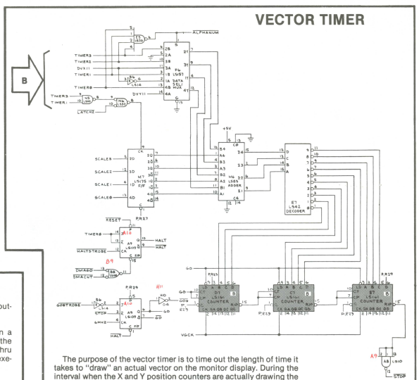
The last little bit that was bothering me was the DrawShort vector Neg Pulse time is not the same as the other DVGs (Asteroids and Deluxe). I looked around for a while on the PCB – but the game was displaying properly.. Then I looked at the schematics.
Here is Asteroids..
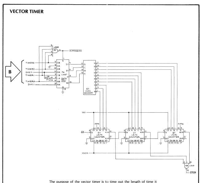
Here is Lunar Lander – The missing piece is the scale section (LS175@M7 and supporting chip). In fact the schematic shows the SCALE outputs on the LS273@K7 – but they seem to go nowhere. Scale and short vectors.. I’m betting they are related.
Now that it is up and running and fully working – I finished wiring controls. I had to add a couple buttons to my Analog bench controller .. but I did add some fun!
Self test rotates the lights that are on the original control panel to select the missions.
Analog stick/bench controller – I use it for Star Wars, Food Fight, Tunnel Hunt and and a few others when bench testing.
Board works!
Board #2 – In for repair
Owner sent it to another shop that decided not to repair it (I believe).. The condition I got it in meant it had either never been plugged on or they made a mess of things..
Here it is once I got started a bit on it. The existing edge repair was ok, but the divot below the repair had not been fixed. Solder blobs across the fingers too.
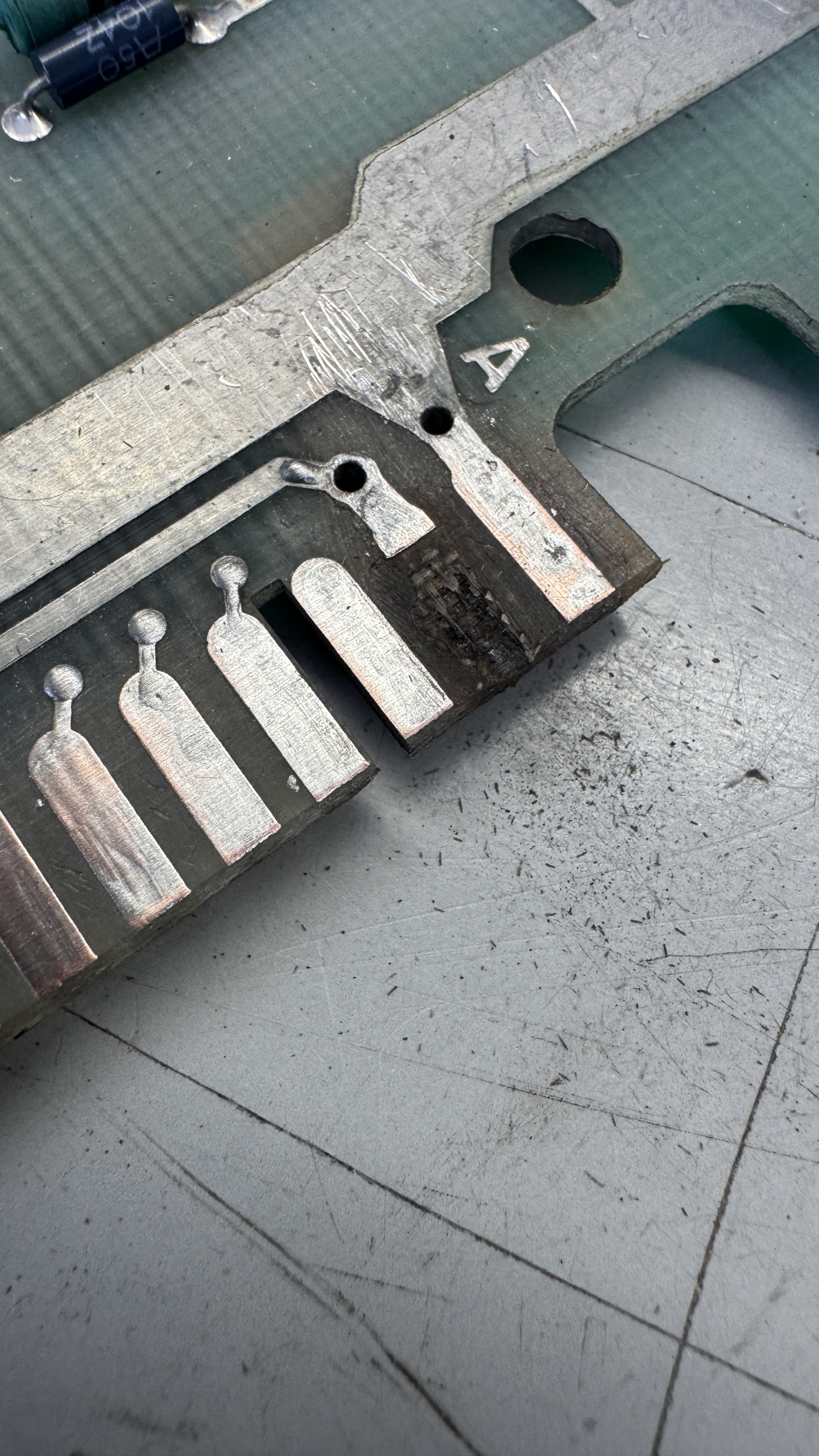
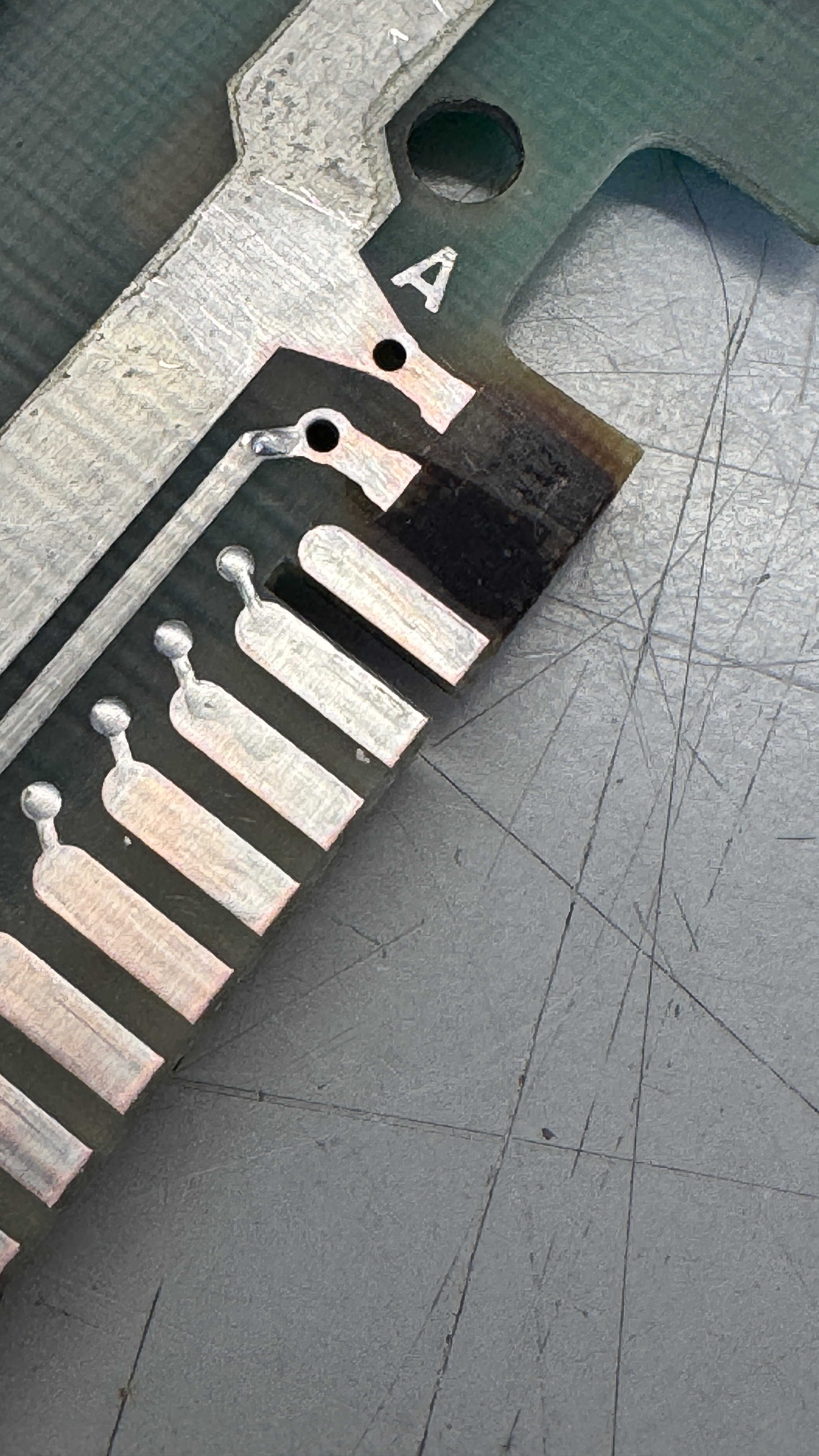
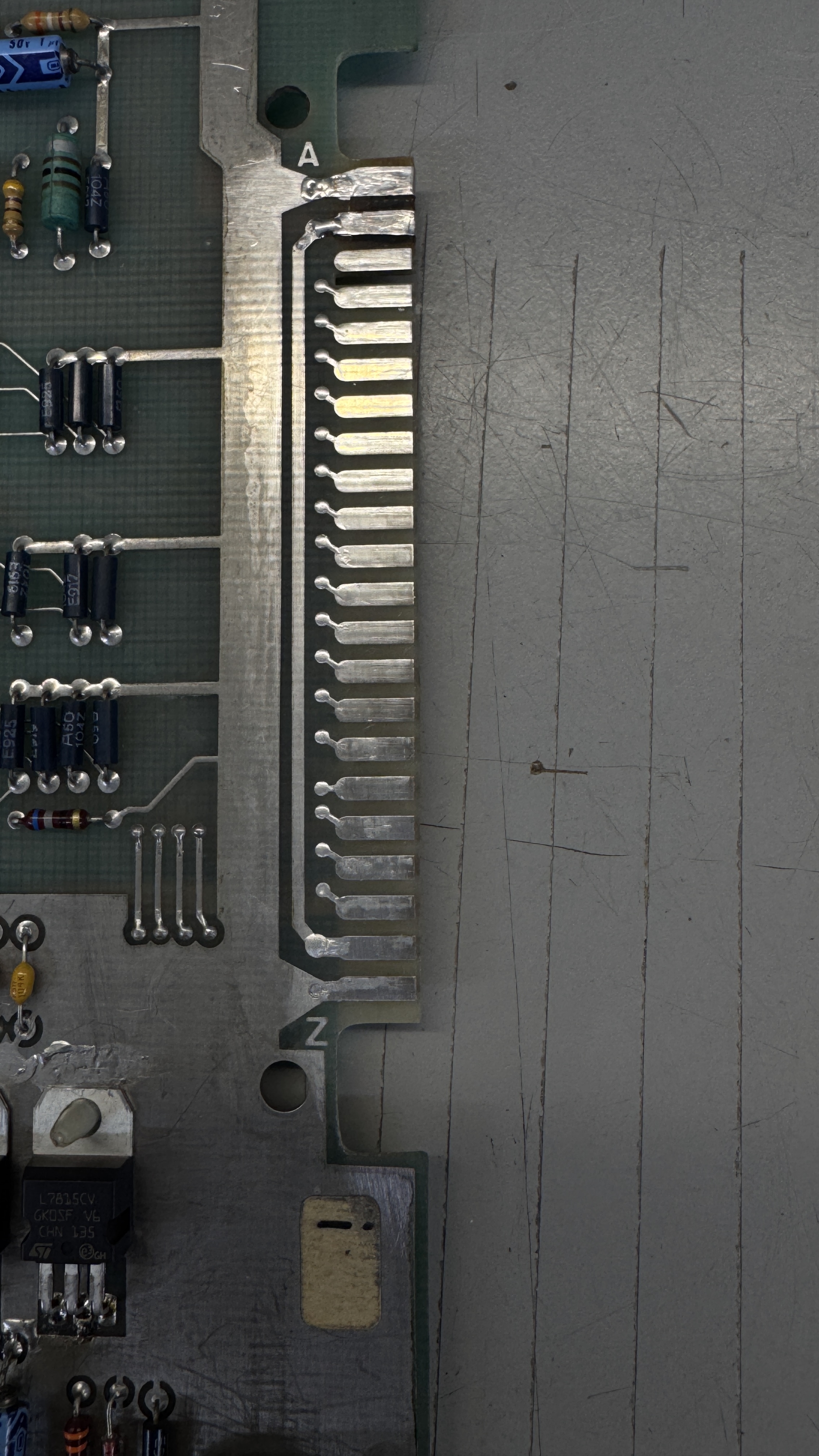
You can see the crater left behind – I removed all of the loose material, filled it with UV Cured Epoxy, sanded it flush and replaced the copper and Liquid tinned the repair.
Once I powered the board up.. It immediately blew fuses on my power brick.. that’s not good. I checked all of the power rails for resistance and checked all the diodes and regulators. The all seemed to be fine. I suspected that maybe a voltage regulator was failing under load?
They had been worked on and needed to be cleaned up.. I had checked something else prior and popped 2 more fuses before pulling the regulators.
To be safe, I left them out and tested again. The input voltages to the pads for the regulators seemed messed up – but the real clue was one of the large caps just next to the regulators started getting real hot. Good thing I noticed it before it popped while I was probing in the area.
Issue: Someone installed one of the 4 rectifier diodes in backwards.
I replaced all of the regulators, diodes, the 2 caps and there were 2 big disk caps that I replaced next to the diodes. The electrolytics tested out of spec at this point. I could now power up the board.
Once connected to the tester. I had a bad ROM@C1
I check them on occasion – large areas of bad data.. Burned a new one. Once RAM and ROM tested correctly. I had no audio. I pulled out my Audio Probe and quickly determined the LM324@7R was bad.
Finally I was able to get to a test screen – one item of interest. If it shows “8, 9, 10, 11” on the screen – that means the French ROMs are not installed. It will not be an issue as long as you are not landing in France.
This last issue took a long time to figure out…
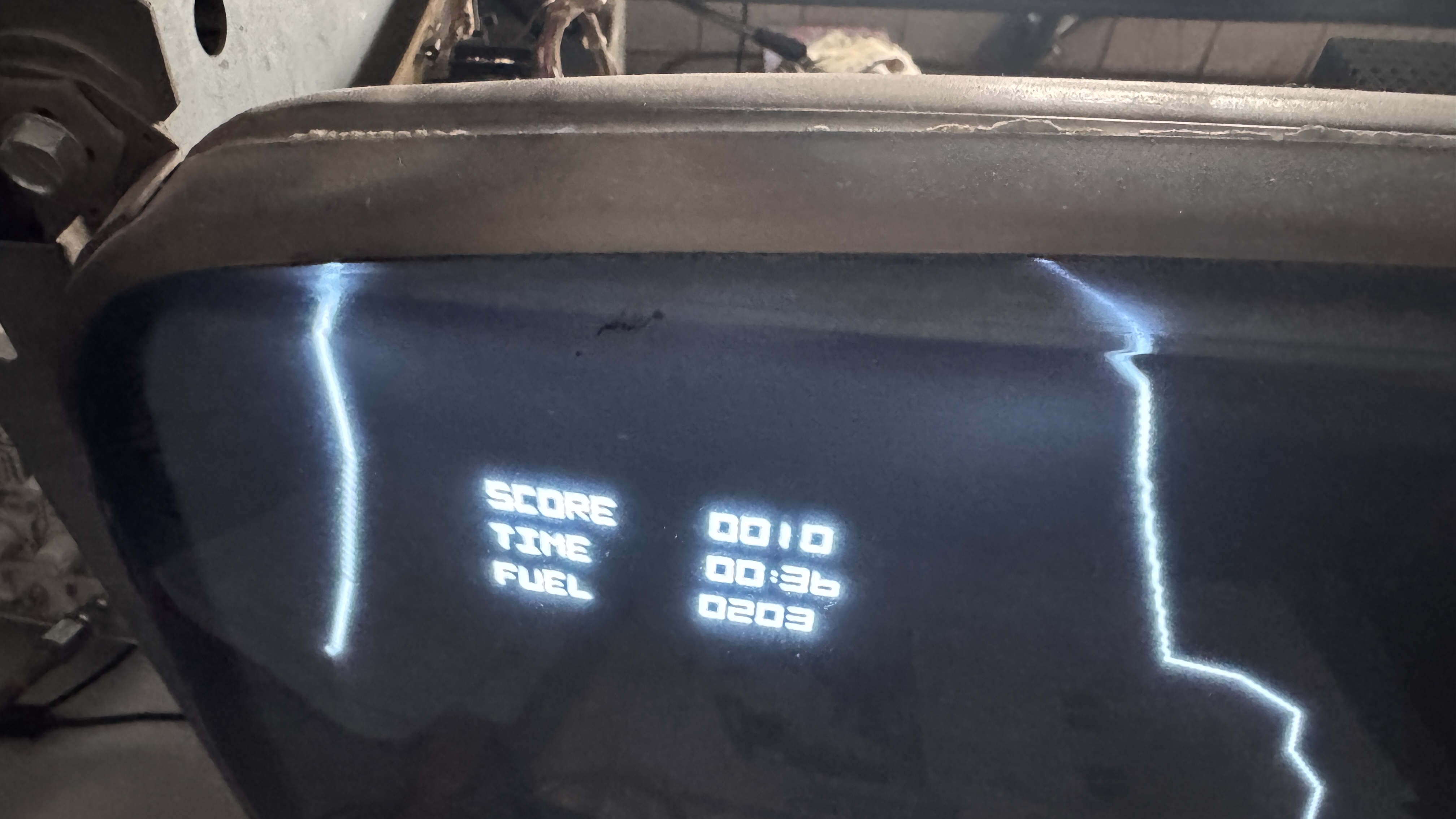
This is a poorly edited video – it is cut to show the actual problem..
– If the ship lands at the very bottom of the screen, the graphics all bend up and to the right.. It doesn’t have to be an actual 2X landing site.. just where Y is approaching zero. However.. If I land at a higher altitude on the side of a mountain. It plays correctly.
I poked around every section of the board trying to determine the cause. All of the vector timings were good. Seemed like it could be a counter issue – logic comparators disagreed. It also seemed like a gate was failing pretty early since the issue was both on the X and Y axis. After a lot of testing and probing.. I came across LS00@C6.
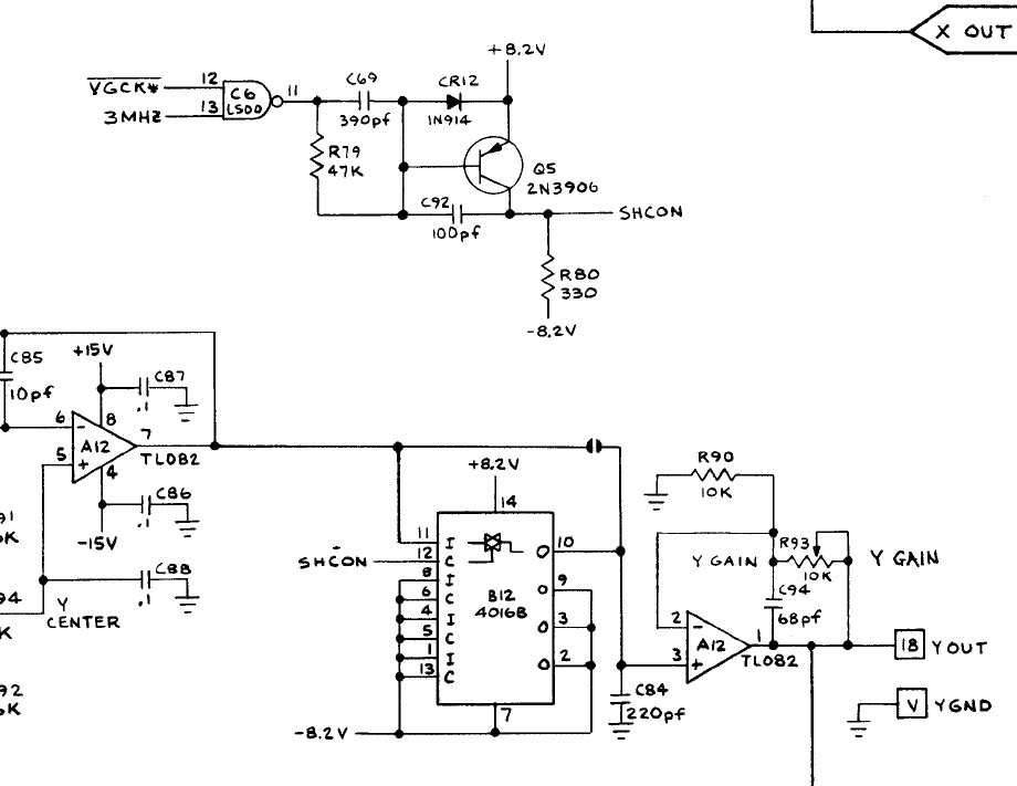
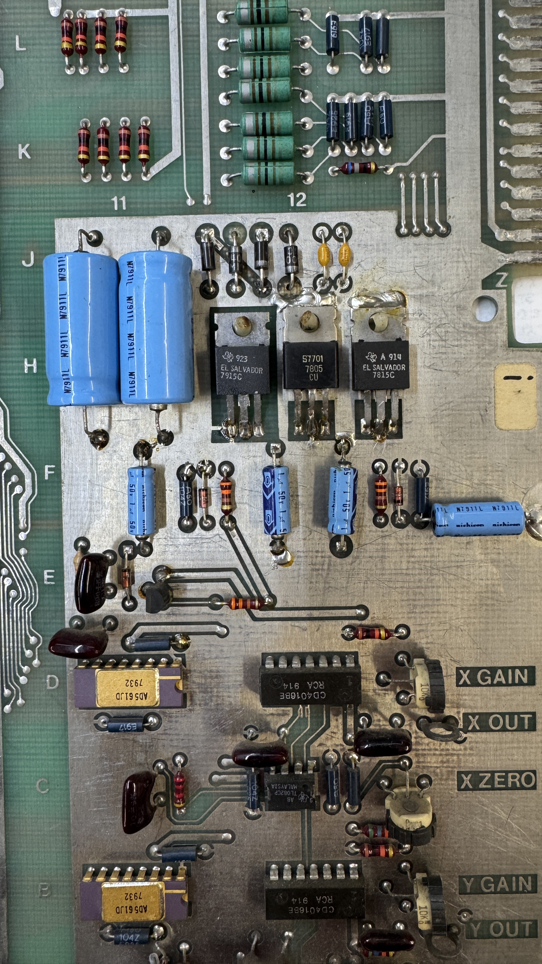
Here @C6 is part of the X and Y output circuits.. But I don’t know if this was the problem. The same chip has a gate on the program stack.
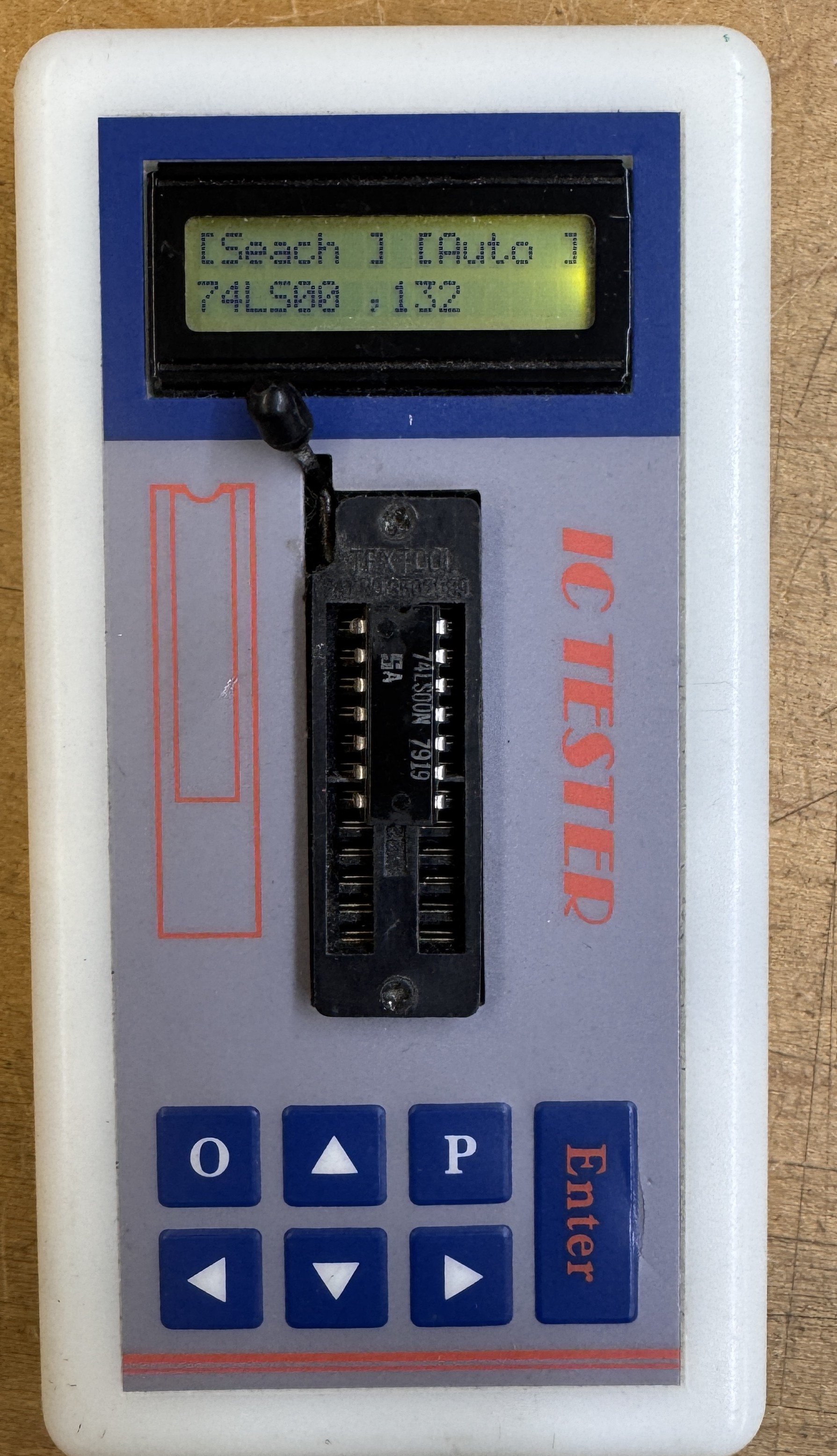
I tested it in this tester and a the TL866 which does a deeper inspection an both show it is 100%, except it isn’t.
One last item – I found a (new to me) bug in Lunar Lander. When the game zooms in for a landing, if the mountains go off the top if the screen – the vectors continue to draw off the phosphor. There is no windowing circuit like the vector games that were only a little newer.
I checked with others and this is consistent on other boards. At first I thought it was related to the Y axis landing issue – which also slowed progress on problem determination.
Board works!
