
I had not intended to work on these PCBs, and in hindsight.. they may be a bit too difficult to repair easily.. My machine is up at the lake and my shop isn’t. I restored my Ice Cold Beer and the board itself is not too complicated. The logistics to work on it are much different.
I did as much as I could do on the bench and then had to drive it up and test. This particular board put up a significant battle and even if my machine was in the shop – it would have been a challenge. Eventually I won .. I always do.. but it was a good fight.
Normally I’d make a bench adapter and plug into my test harness. This one is different – I’d have to essentially build a bench version of the game and at minimum simulate the motors and end stops.. It would have been too much for aboard I’ve only been asked to fix once..
This PCB had a number of issues – the biggest one was that at some point – someone decided that the transistor bank that did the heavy lifting had an issue and destroyed that section of the board.
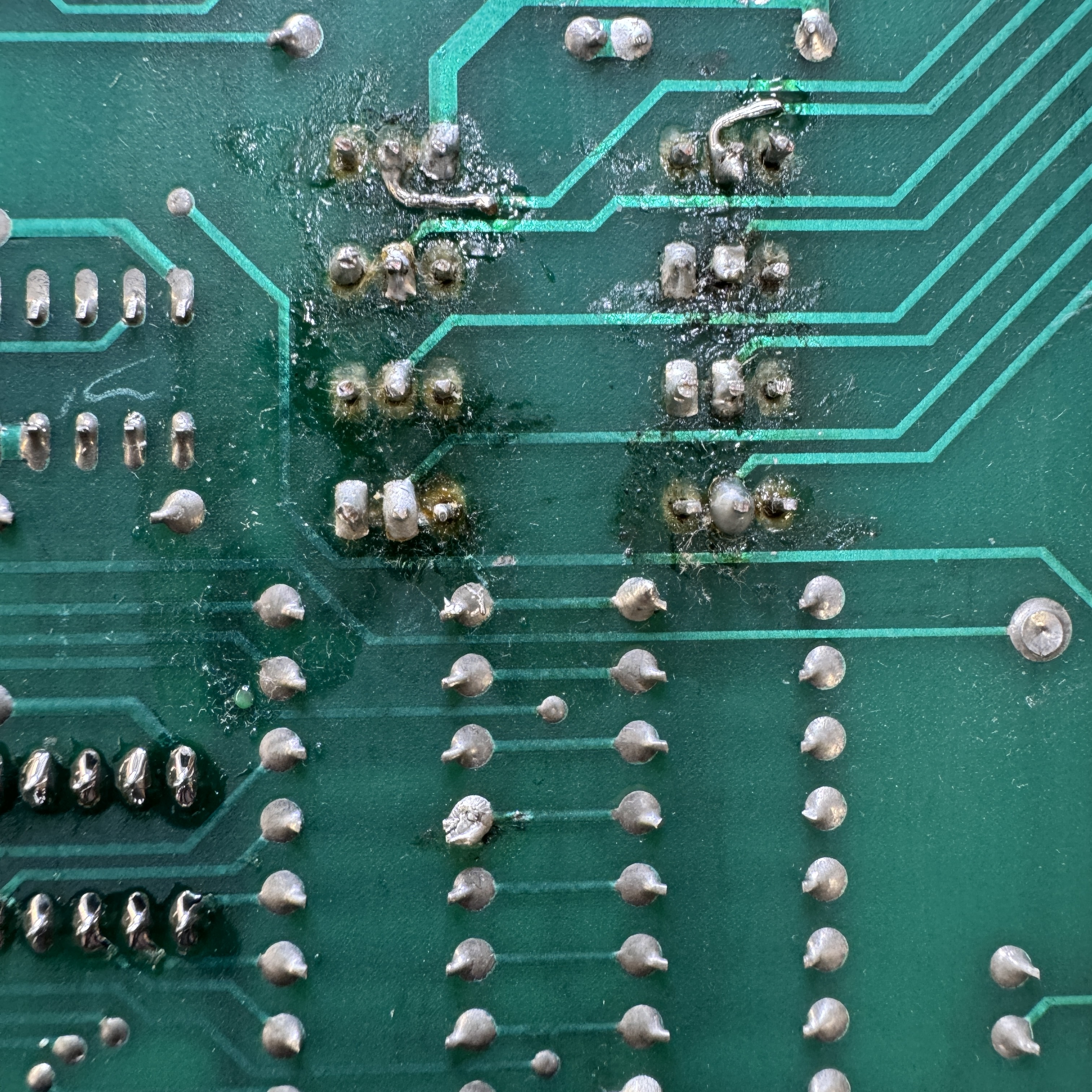
Here is the mess on the solder side and me removing all of the transistors on the parts side. The traces were pulled up and just missing.
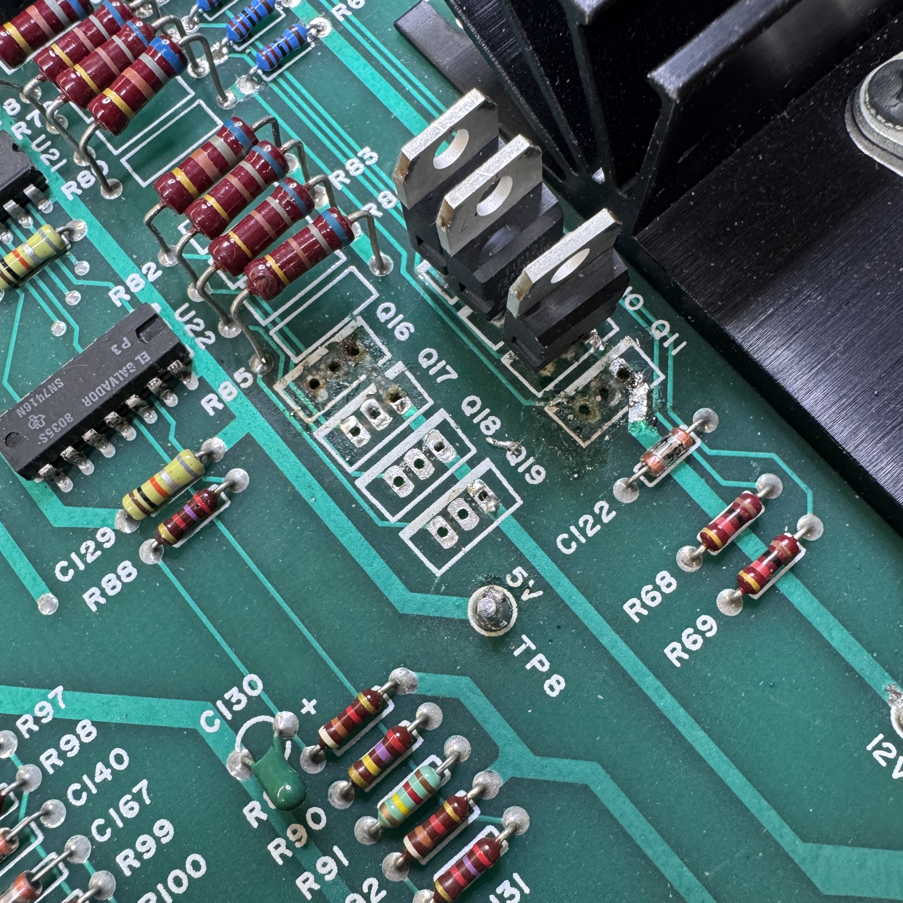
After getting all of them out and beginning to sort out what repairs were needed – I did not want to directly solder the transistors back in place. If one ever failed – it would have ruined the repair. It took some searching but I found transistor sockets (see Q19) that would work. I could repair the traces and use sockets. This took a few hours to get all back to gether.
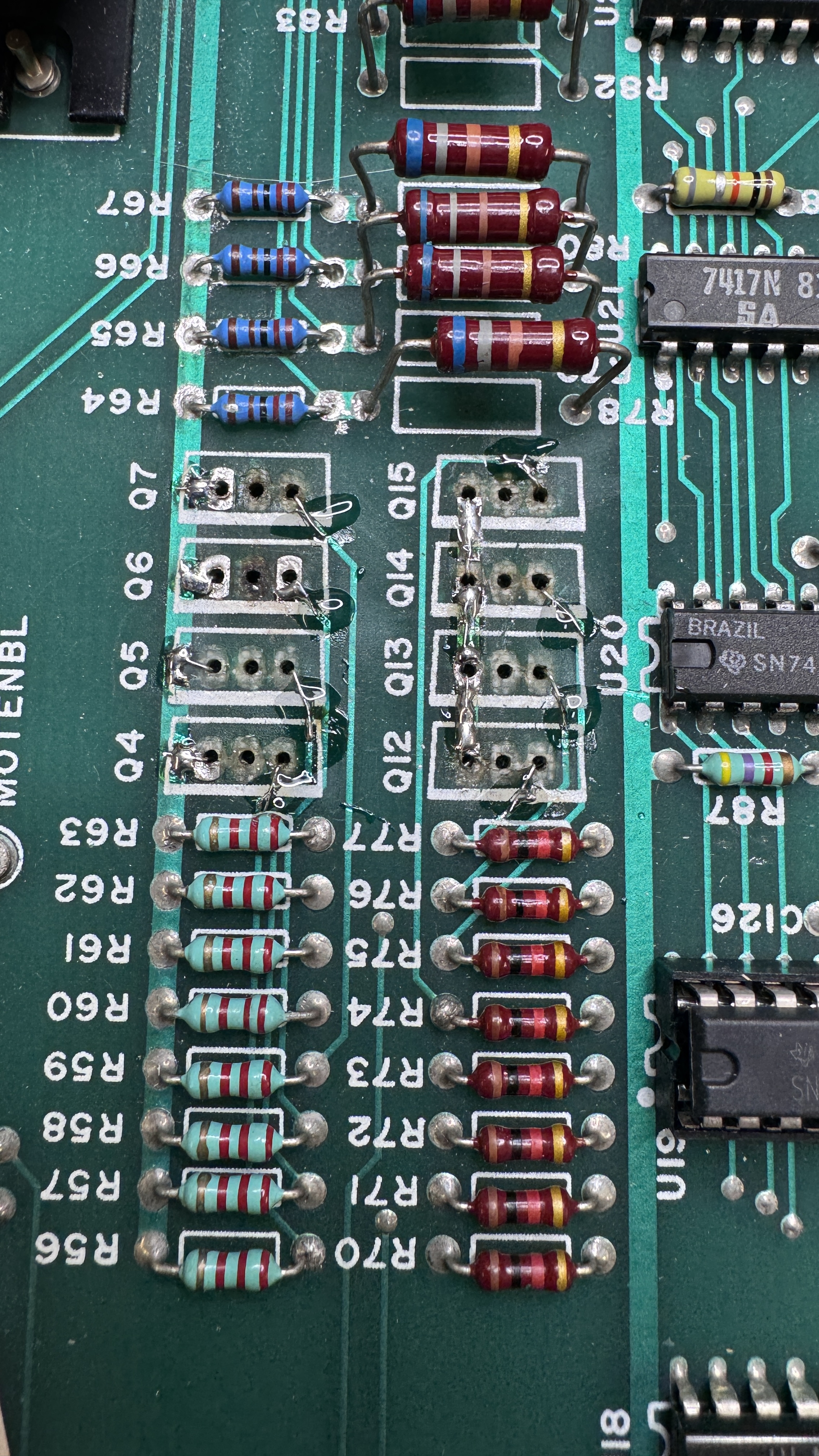
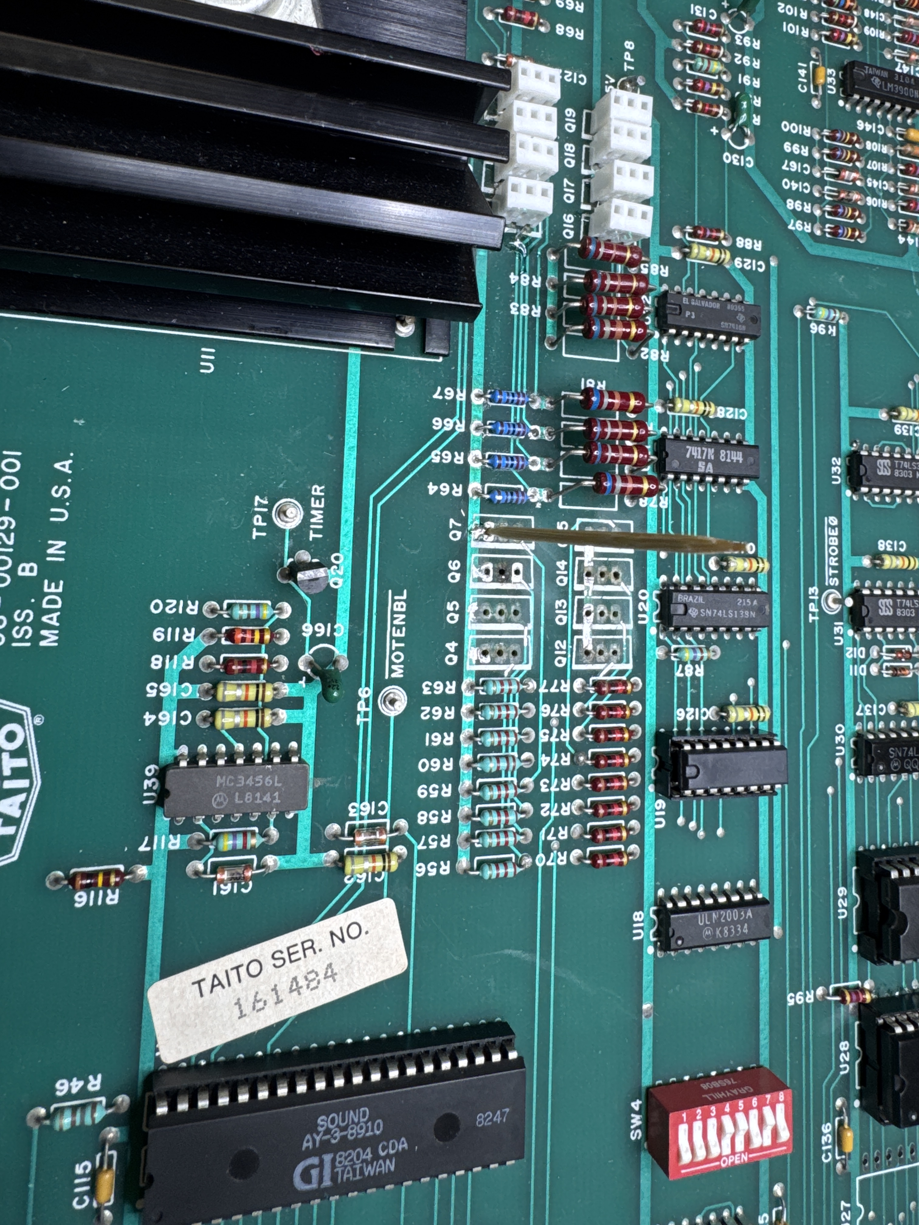
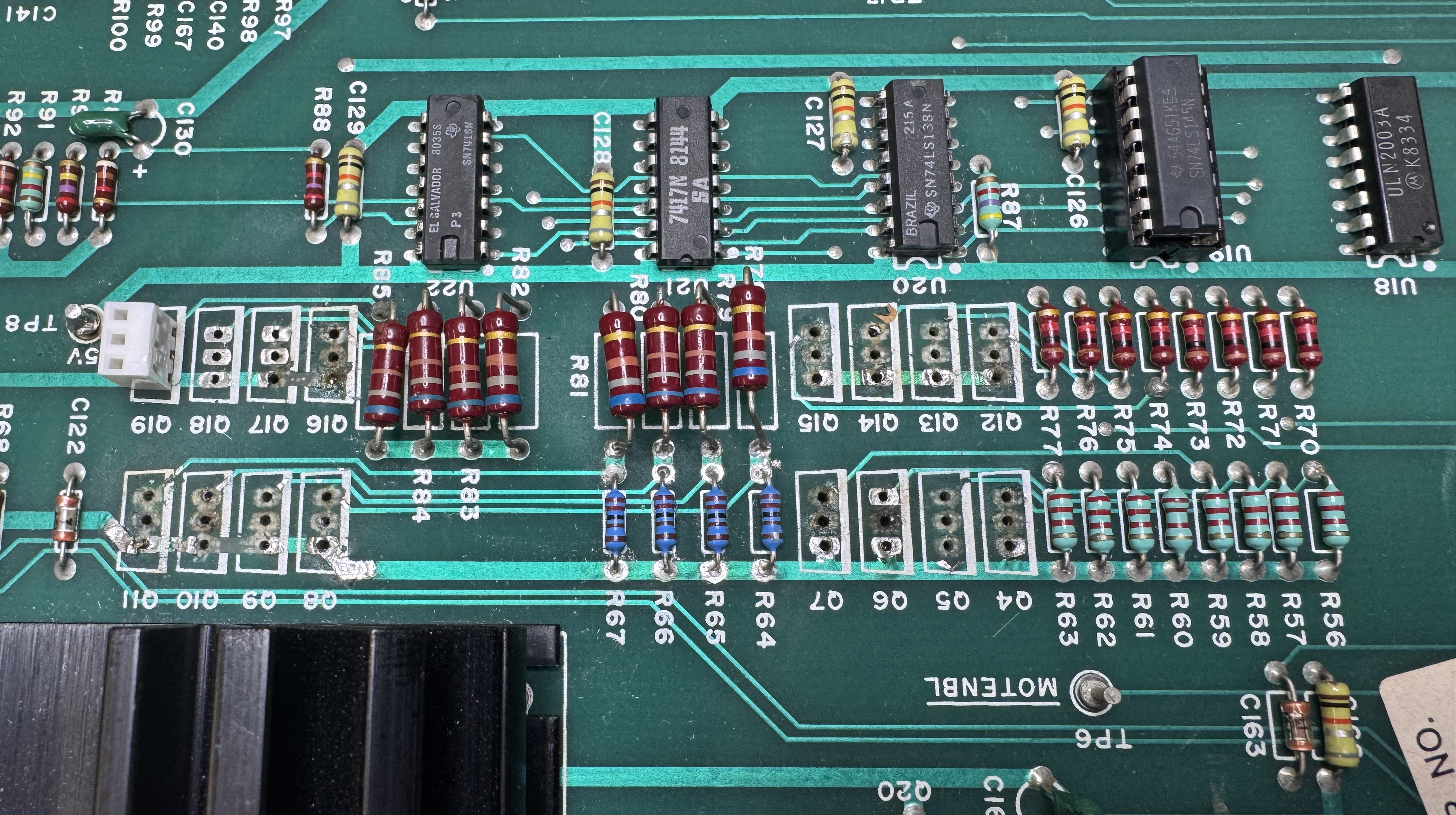
Here is a bank of repairs.. Each has a Kynar wire connecting the via to the trace. The clear glob is UV Cured Resin that I can put in place as glue and cure it hard in 30 seconds. It holds the wire while being soldered so it doesn’t pop off. Second pic shows the first set of sockets in place.
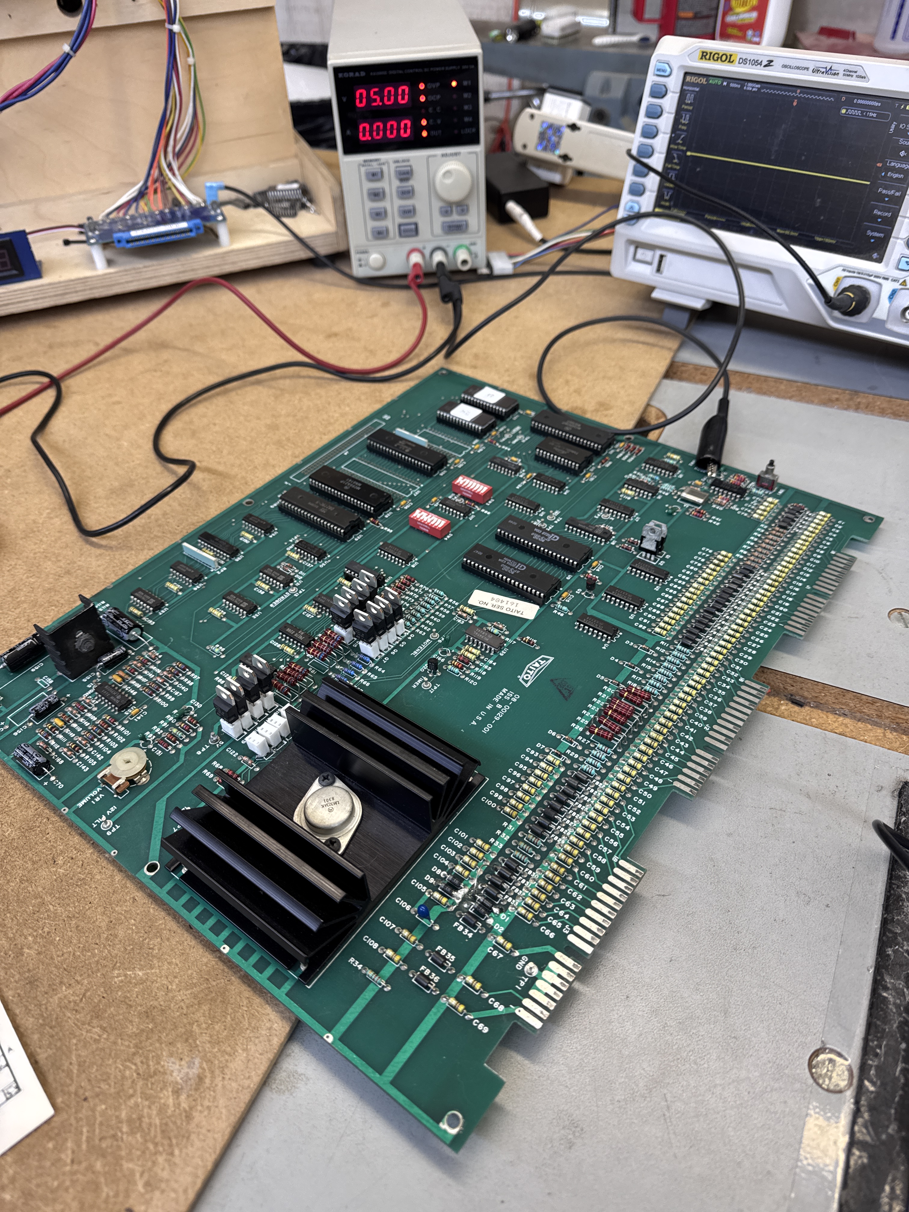
Once I got it all together – I was able to test somewhat on the bench. I even hooked up a speaker and could get it to take a coin and hear the whoosh sound.
After that – it was some work. I’ll summarize some of the issues:
- Blew fuse first time testing in cabinet
- Audio amp failed.
- CPU failed
- Voltage regulator would shut down – that took a little time to figure out. It was unable to provide 1 AMP and it was rated for 3A.
- U1 – LM3302 was not working so that the diag switch could be used.
- Replaced a socket.
- There was more, I stopped tracking it all.
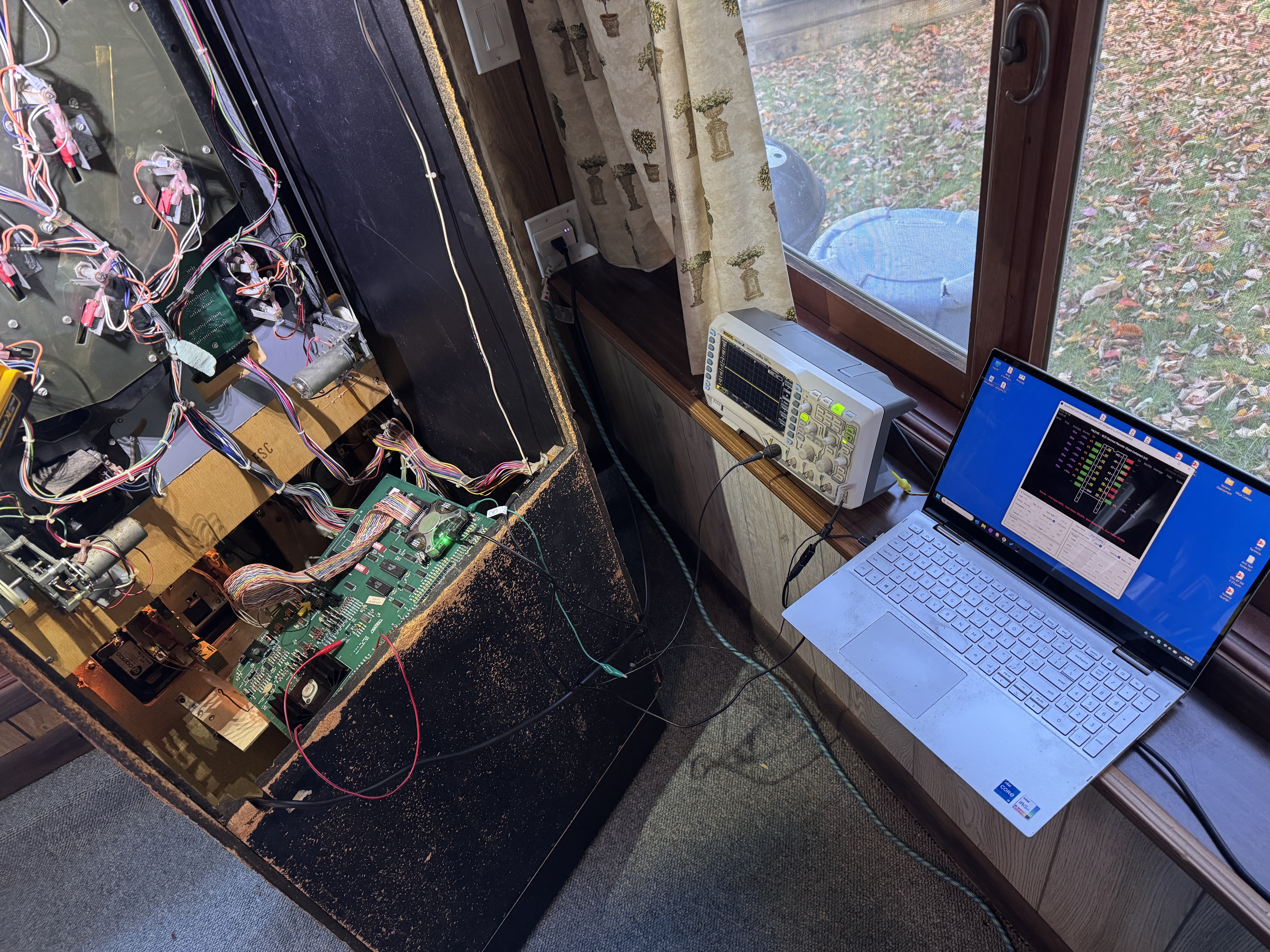
I even trucked up a number of my tools to work on it, not ideal.
Eventually I worked through all of the issues and it ran great for a number of hours and I almost recorded my first 10 in a video. It took a number of trips back and forth to the lake to work out the kinks.
Board works!
