
*** Newest Entries always added to the bottom ***
My plan had always been to work on Pole Position PCBs. I have 4 or 5 sets myself, I just never got to them. My test bench adapter was rather easy to assemble as compared to some other ones I’ve built. The video board is just 5V+ and the video signals. The CPU board is just 5V+. While getting set up for the very first time, I pulled out some of my boards and amazingly I got a fully working set. GREAT! Reference boards!
Board #1 – In for repair
Initial board cleaning took almost 3 hours. Over 50 chips removed, legs cleaned, boards washed and inspected. Sockets Deox-it, chips Tarn-X, etc. That was only the beginning….

Remaining maintenance work was to replace the existing edge repairs (they were way too thick, I measured with calipers) and repair battery damage on the CPU board. After all that maintenance, I wanted to see if the video board worked…

It’s all jury rigged together at this point, but RAM3 error – replaced ram @7H and cleared it! Video board was up and running with my CPU board. It’s obvious why there are 2 ARII’s in a Pole Position. The video board alone is pulling 4.5A.
A year ago when I decided to work on PP boards, I designed this Pole Position Bench test adapter for the interconnect so I could lay the boards flat. I never got around to testing it until now.

The first time I fired it all up it worked! Unfortunately it works ‘unreliably’ at best. Some boards it works and others it doesn’t. I get RAM errors on the bad ones. If I put the factory interconnect on – RAM errors clear. I would think at the slow speeds of 1980’s technology, timing would not be an issue. I’m not an electrical engineer.. so some of this is guesswork. But I hypothesized – maybe there is crosstalk/noise because of the ribbon cable?
As a test, I carefully separated this ribbon cable over the course of an hour…

Same CPU board, different video board. Random memory errors. bummer. Then I thought, resistance? I checked resistance point to point on the factory interconnect. It was anywhere from 0.1-0.2 ohms. On my adapter – if I checked the resistance on just the ribbon cable connections on the back of my PCB – 0.2 ohms connector to connector. (good)
Testing out to the edge connector.. i.e. including the PCB traces. Testing grounds – I still get 0.2 ohms. This is because I had wide ground traces in my design. Testing the data and address pins, I get 0.4 to 0.5 ohms end to end. My current theory is I accidentally limited current to such an extent that the boards cannot drive whatever is needed on the opposite ends. I used the default trace widths in KiCad. I’ve revised the design using wider traces to see if this will provide consistency. It would be great to be able to reliably test these boards flat on the bench. Stay tuned – I’m waiting for the new PCBs to show up..
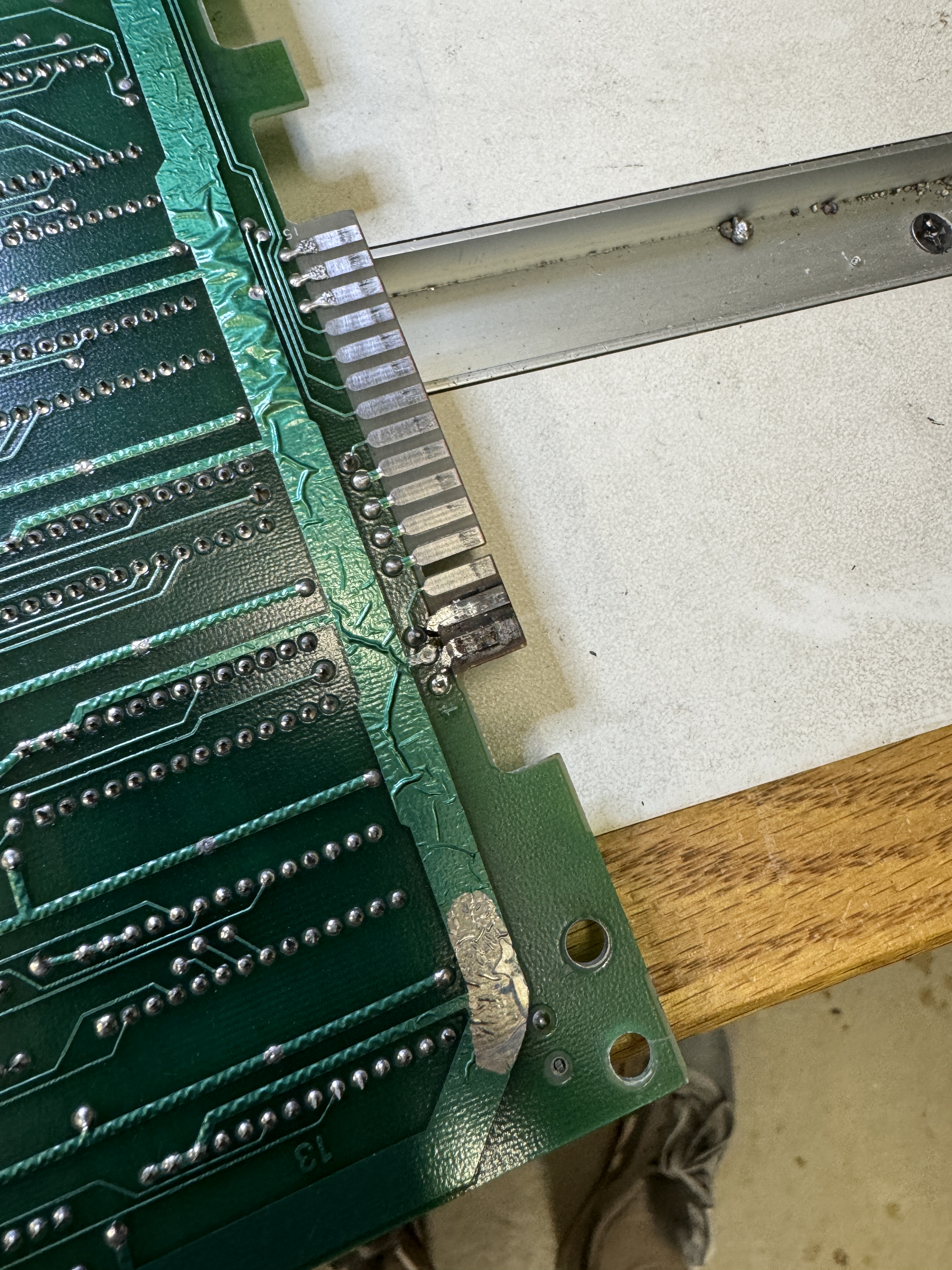
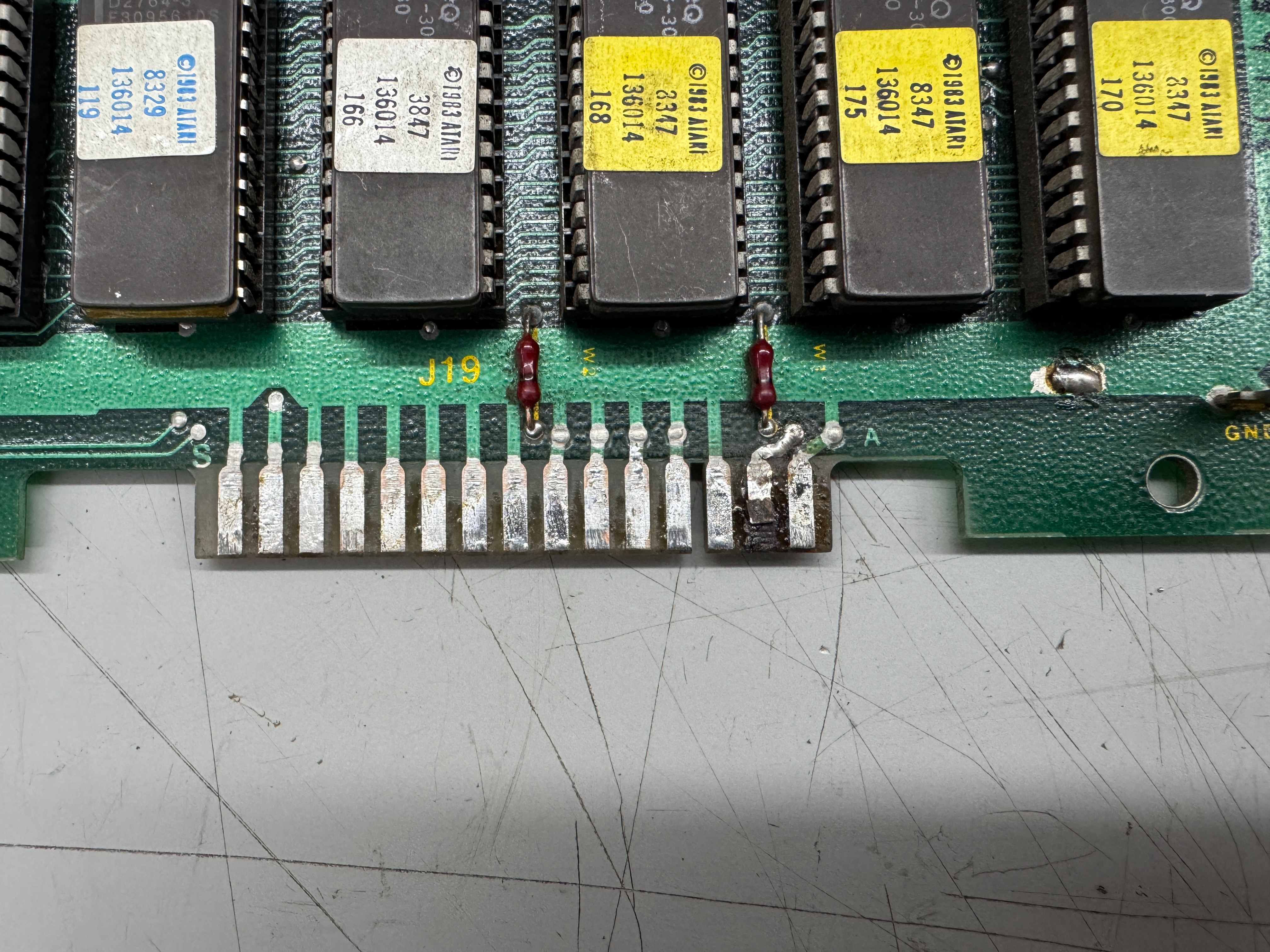
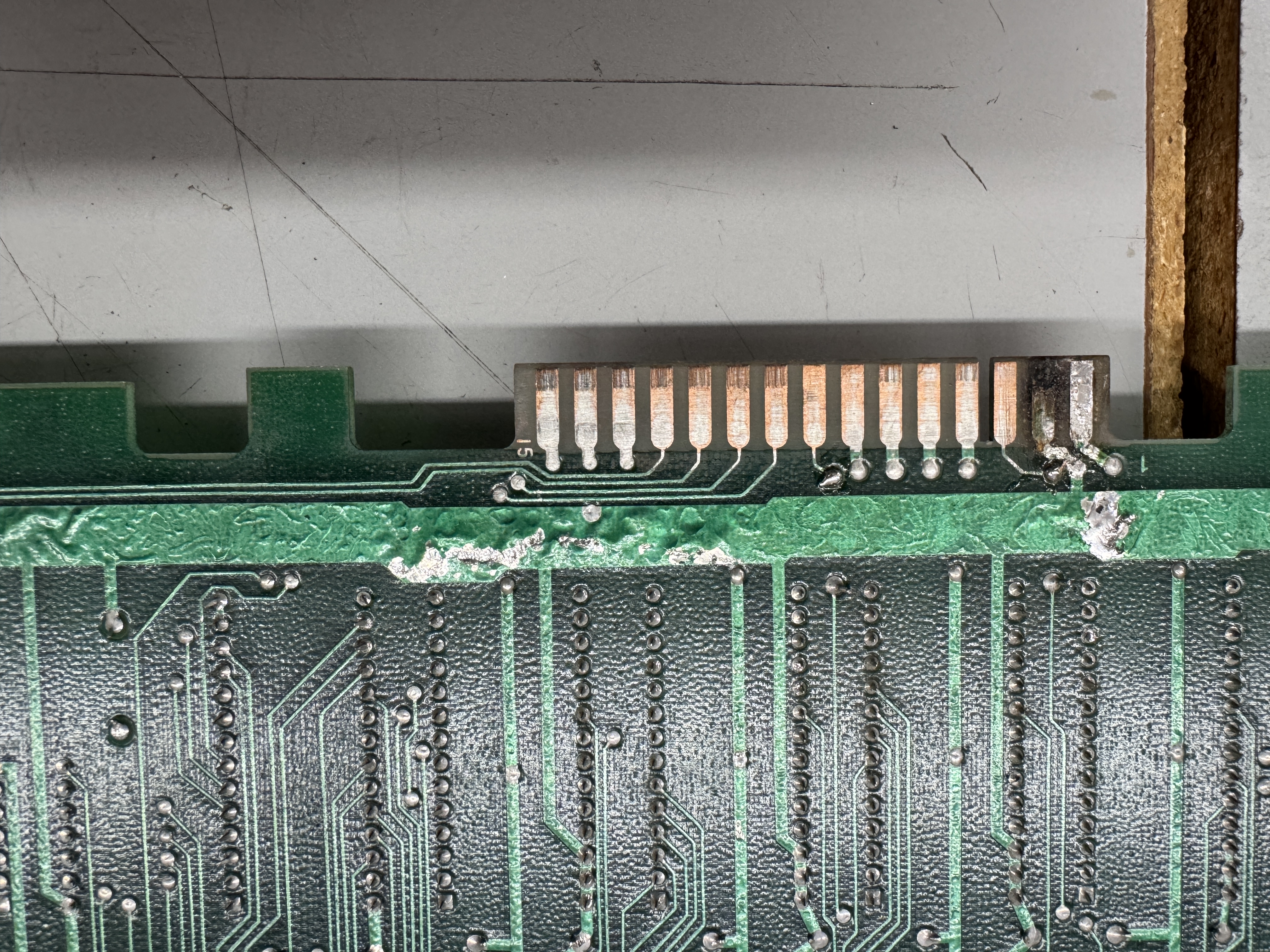
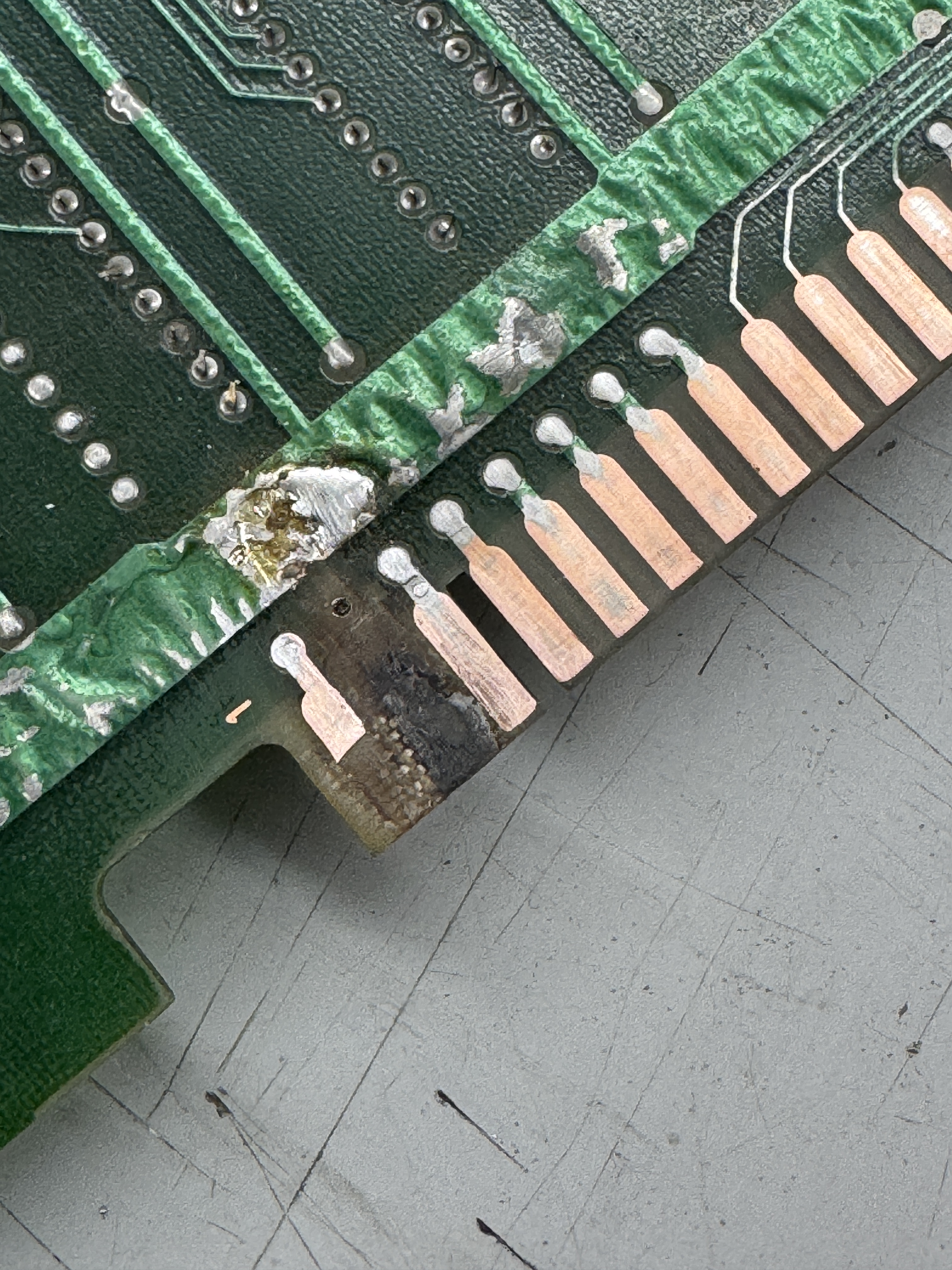
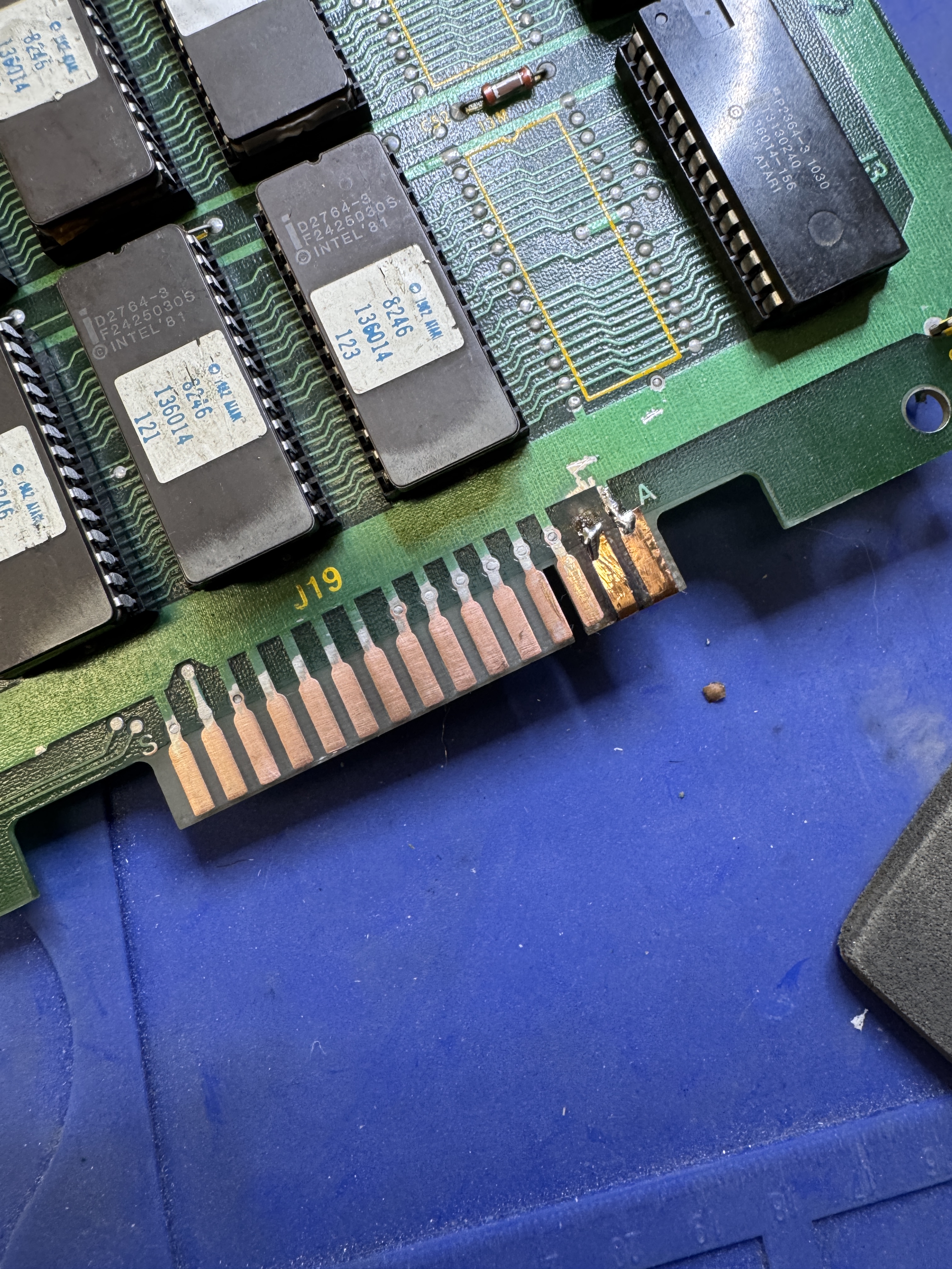
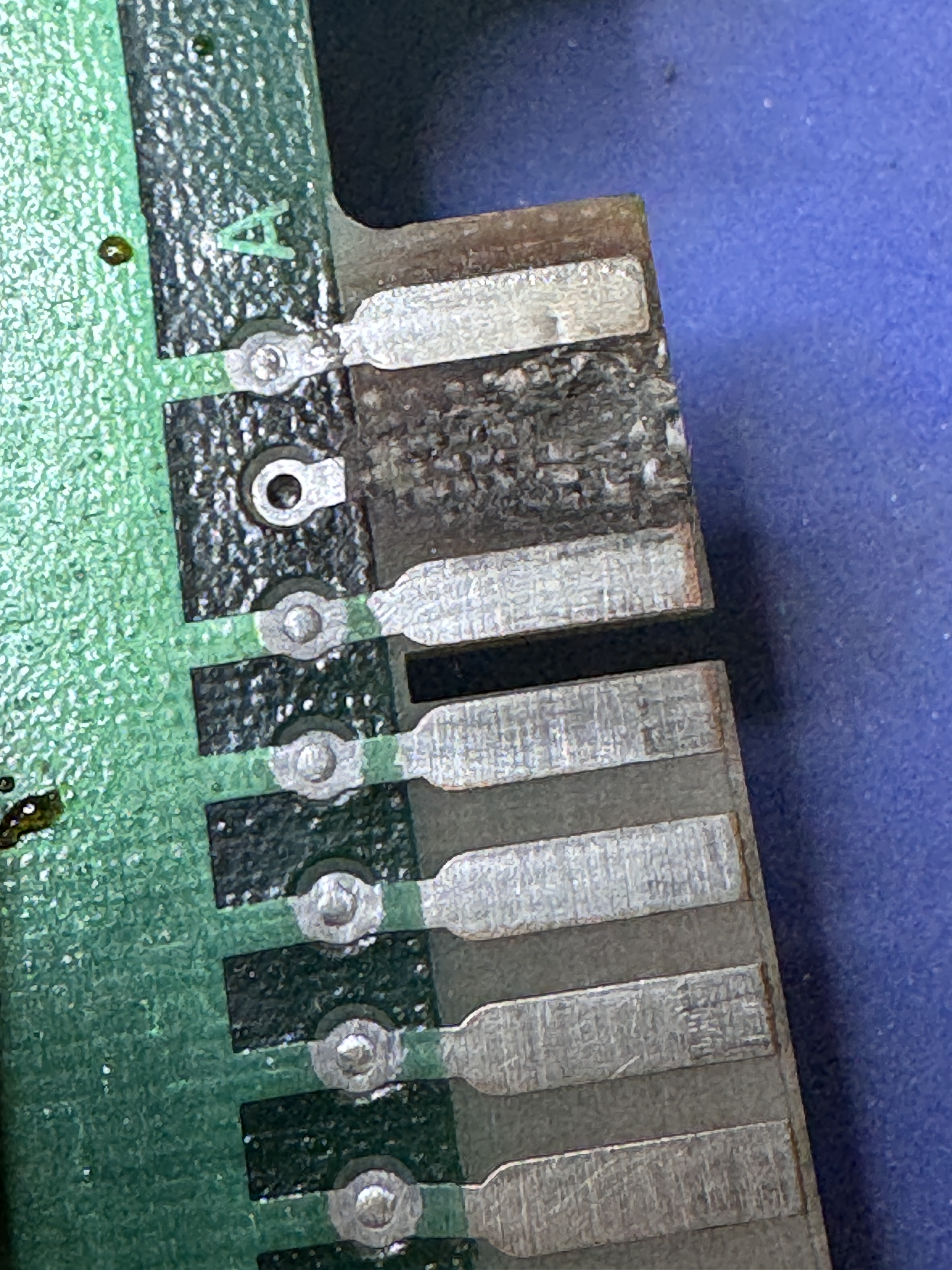
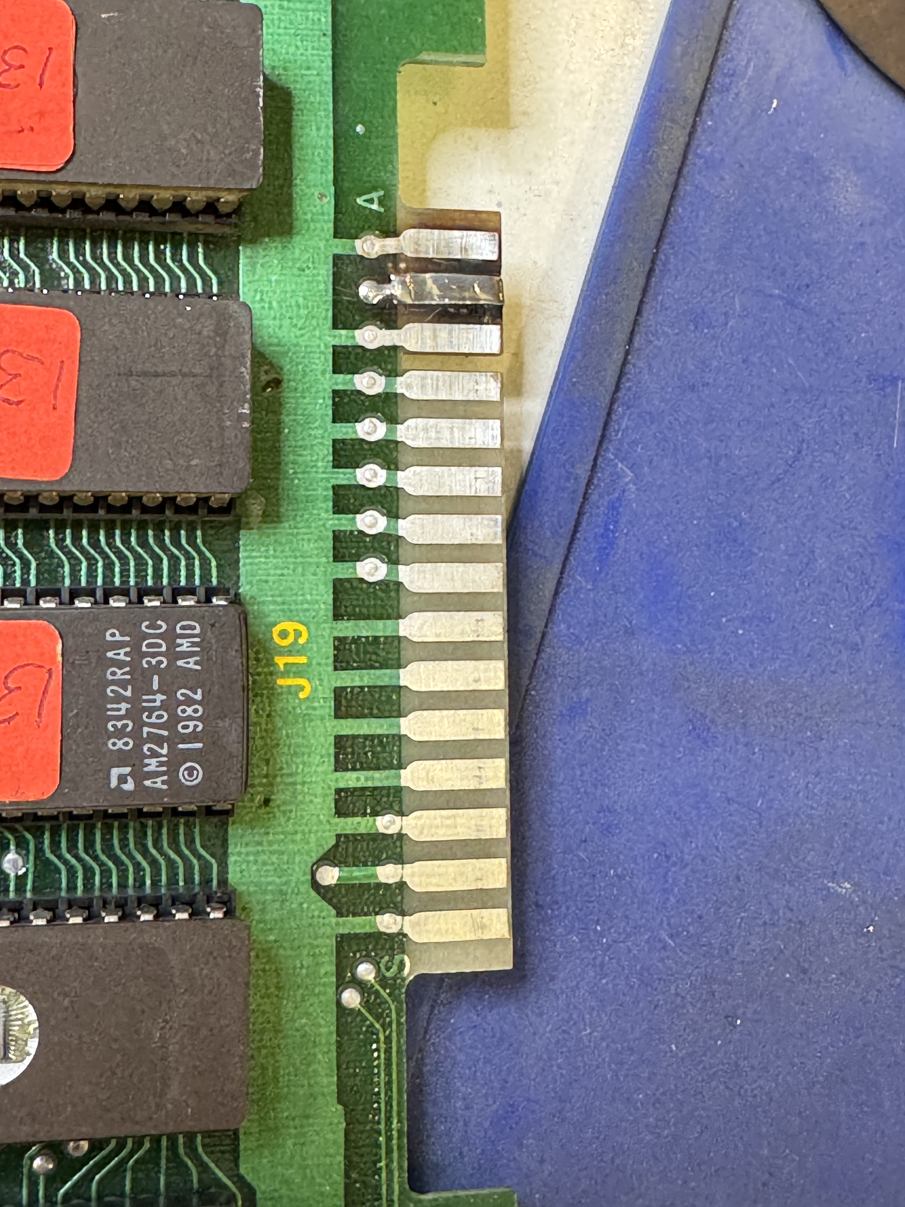
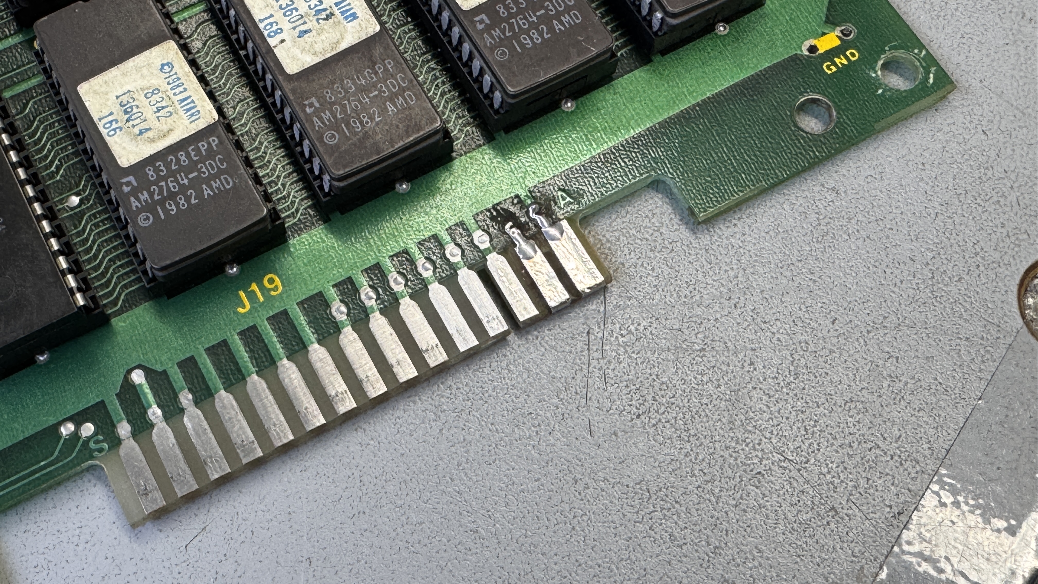
On to the CPU board. I wanted to clean up the edge connector repairs.. I’m sure they worked, but they were extra thick. After removing the bad ones..


You can see the divot from the burned up finger. I found this UV cured resin that has worked great for lots of these types of small repairs. Filled the divot and then using a razor after it is cured, I scrape it down flush with the PCB and added copper tape. When they are all done they get coated with liquid tin to protect all the copper.
On to the battery damage..


Not as bad as a couple of my other boards. But needed to be addressed. I used etching acid to help with the alkaline damage front and back. There were also solder side jumpers which I removed as part of the repair (not a fan and I remove them whenever possible)
After the first time through, it had removed the surface damage, but more importantly it helps the damage below the solder mask bubble up enough to be scraped off easily. At that point it got a second application of acid to get the rest of it.

From here I used the fiberglass pen, a wire wheel and some sand paper to try to polish up the copper traces as much as possible. I also removed all the jumpers front and back and repaired the traces on the parts side. After all the cleaning and giving it a coat of liquid tin…

Not bad for my first PP board. Next one will be even nicer looking.
Finally.. on to actually repairing the CPU board!
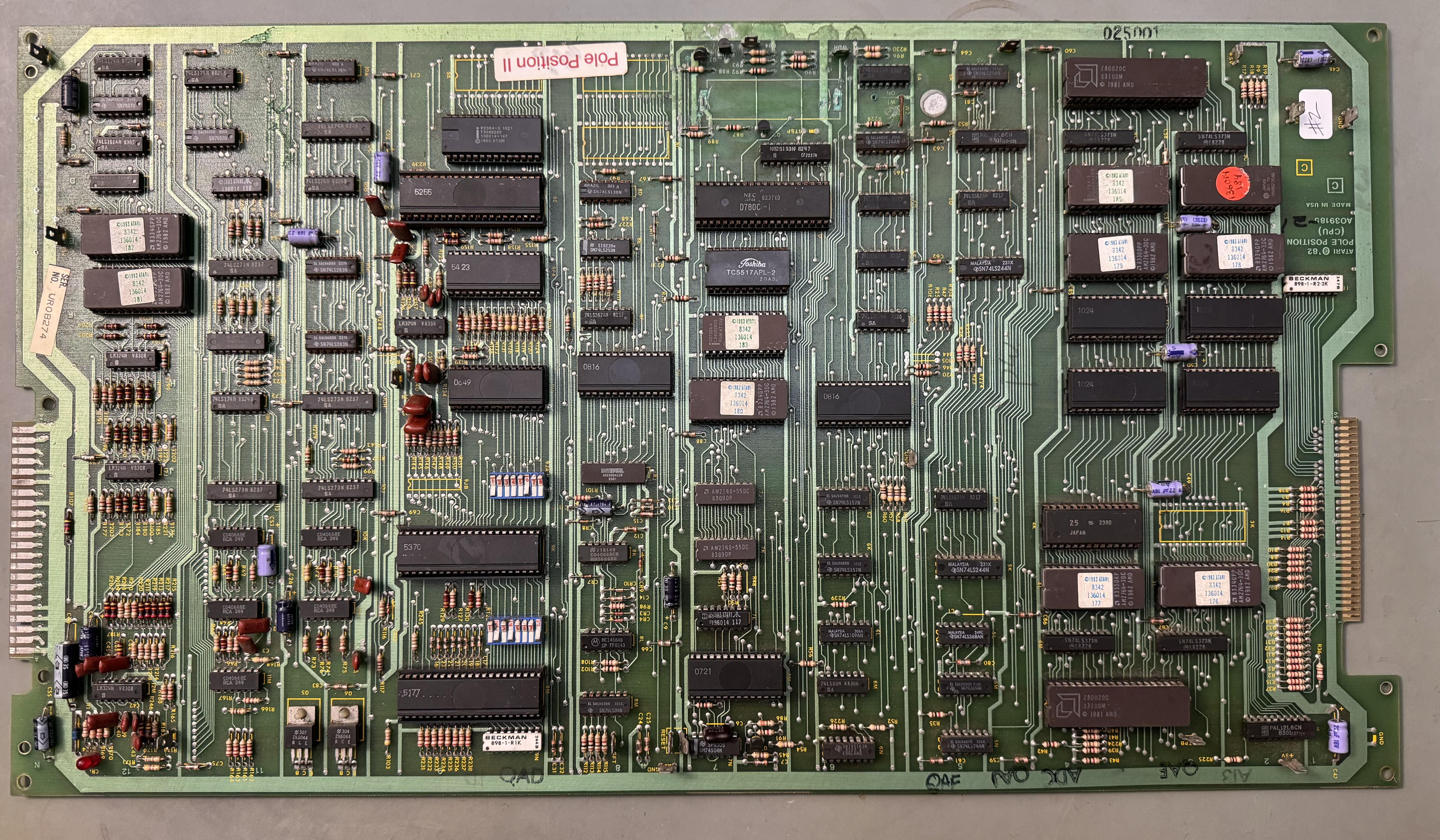
Connected up to the CATBOX and all the video RAM tested bad.. Replaced the WDF test point which was missing so I could disable the watchdog. After a lot of poking around since this was my first PP repair – I determined the RAM was never getting write enabled. Backtracked through the circuit and found this area:

This custom is the traffic cop between the D0, D1, D2… data bus and the DB0, DB1, DB2… data bus it seems. Video RAM is all on the DBx bus. However it was never getting enabled @PIN27 SYSDBENBL. Working backwards again..
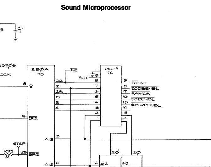
The PAL@7C Pin 15 was dead. I pulled one from one of my other boards and now all memory tests pass. It wasn’t battery damage or a broken leg.. Just that pin didn’t work. I suppose alkaline could have crept up the leg .. maybe..
My last issue was the voice cutting in and out randomly.. At first I thought it was a bad socket, nope.. These little guys were just close enough to sometimes touch and sometimes not.. Missed it on initial board inspection.

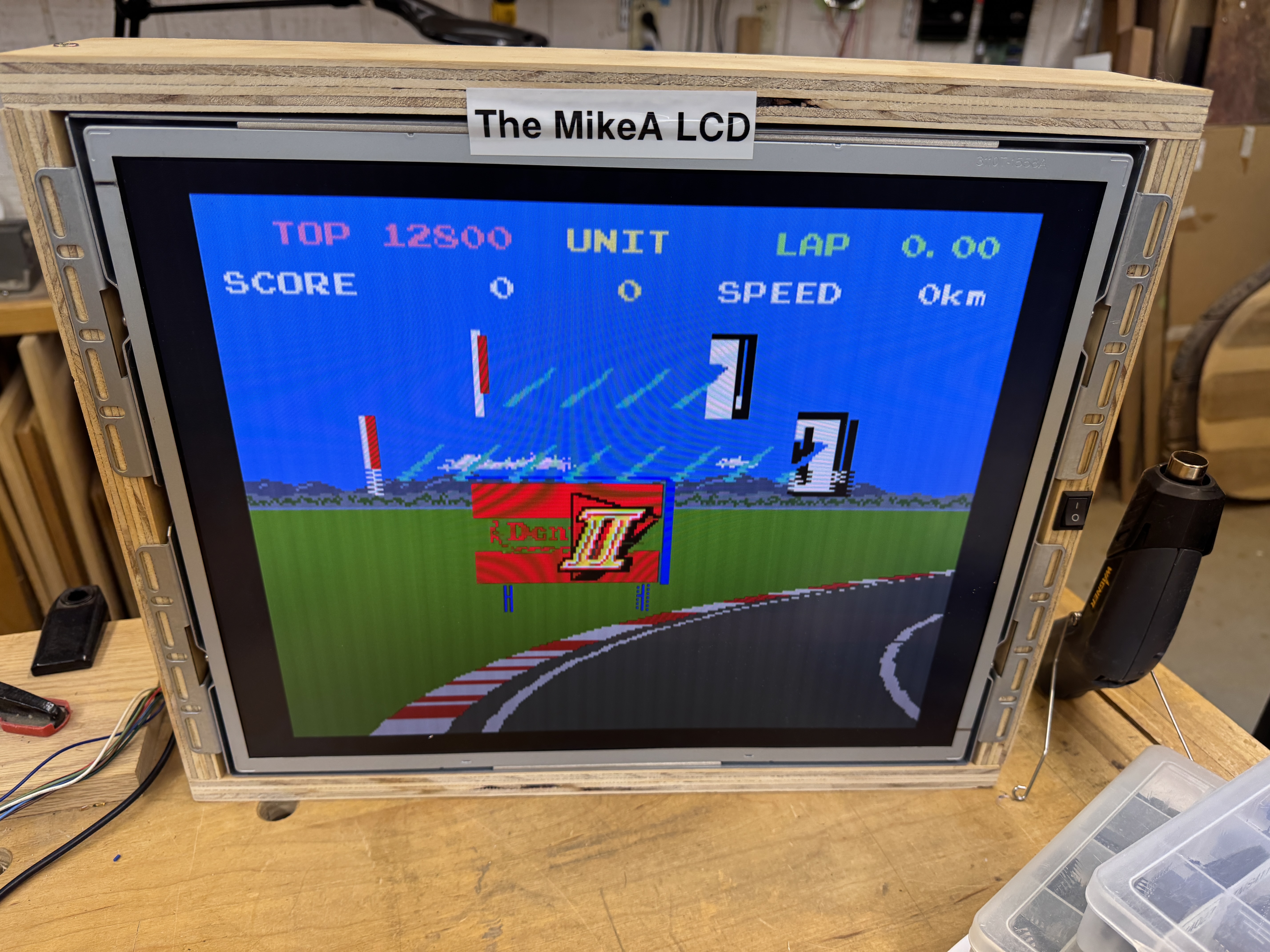
Full testing happens in my Pole Position Cabinet, however I do like to be able to test on the bench to limit the back and forth. I’ve built up a few different controllers for my test rig. The trackball controller was best suited for the task in this case.
Testing with my steering ball, gas knob and shift rocker switch!
Board Works!
Board #2 – In for repair
Technically this is the third PP I’ve worked on. The real #2 is one of my board sets. I cleaned it all up connected it up and it worked. Someone sold me a working set. I’m guessing cleaning the tarnished chips fixed it. I didn’t bother to plug it in before cleaning.
This Pole Position II set was sent in and I wanted to work on it because my personal cabinet is a PPII and I have a non-working original board set with matching serial numbers for that cab.
Between this board and the video board – cleaning all the chips, verifying all the ROM and RAM, etc. Nearly 4 hours total with cleaning up of alkaline damage.

This one as not as bad as most. I cleaned up the damage with acid, fiberglass brushed it all down to copper and then used liquid tin to recoat it. It tends to be a little blotchy at times.
Right out of the gates – ROM 182 and ROM 106 were bad. Many of the CPU board chips had broken legs and were rotted.
I first plugged into the Z80 CPU with the FPGA Catbox. I was not able to see RAM/ROM. Same as the first board I worked on, the PAL@7C was not working correctly. I socketed it and replaced with a GAL16V8. Now I can see all the RAM and ROM. Visible to the Z80.
I had put all the customs and CPU’s in that came with the board (that had legs) and started working on it.. After a while I realized this was a bad idea. I stripped the board of all this stuff and put all known working customs and CPU’s in and started over. New rule on PP – Just do this.

Here are all of the socketed chips that are dead, rotted or otherwise partially working. All 3 CPU’s, All 3 big customs, RAM, couple of ROMs, PAL and the color prom from the video board.
Once I got all the good/bad separated, things went a little better. All of the sounds 1-16 were messed up. They had a beepy quality to them. I spent a little time poking around until I came across the 74LS283@10F

Replacing this restored the sounds and brought forward a new issue. Many of the sounds began or ended with a popping noise. More poking around and I found the CD4066 analog switch @10L had a bad pin 8. Replaced it and cleared up some of the popping noises. What was nice is that it tested bad in my cheap Chinese chip tester. Still had popping sounds and distortion and I found a bad pin on CD4066@11L – it tested bad and helped clear some of that up.
Now it seemed the tire sound was distorted and it faded in and out sorta.. Since I had 2 bad CD4066’s I replaced the other 3 in this area because they all had the same date code, but it made no difference. I stepped to sound 17 in the DIAG screen and determine the waveform of Pin3, CD4051@11F was different than that of a working board. Had to ‘borrow’ a chip – replaced it and proper tire sound restored.
During all of this I tried to save the original IC-25 custom. Spent time replacing chip legs, etc. All for nothing – it was dead. I’d tried using the ROM workarounds, but they were not cooperating and the info out there was a bit confusing. @TimePiloteer on KLOV to the rescue.
There are two ways to replace IC-25@4K. The two ROM replacement or the three ROM replacement. I opted for the 4K Two ROM set
Burning new 2764’s with the 176-V3.3L, 177-V3.4L images and using the ROMs at those locations will effectively replace IC-25@4K. Leave the @4K ROM slot open. I did fight with these a bit and determined the Z8000 CPU’s are particularly sensitive to the EPROMS. I burned these at the same speed as the 2764’s I replaced @9C and 12E. Those are addressed by the Z80. They work fine. @3L, @4L are addressed by the Z8000 and they were not working. @TimePiloteer told me to do a total of 6 writes on the GQ-4×4 to saturate the 2764 EPROMS. It worked. Big win on this!
Last item was the checkerboard on the track edge was Red/Green vs. Red/White. Color Prom 191@4L on the video board was also bad. Hopefully that was the last of it….
It wasn’t.. I was doing a few final checks and then cleaned all of the flux from the back of the board. Connected it all back up, board would not boot. Seriously?! Checked for loose chips, etc.. nothing.
Plugged back into Catbox and it was not reading RAM@7E. Tracing signals the chip enable CMOSRAMCS was being dragged down for some reason.


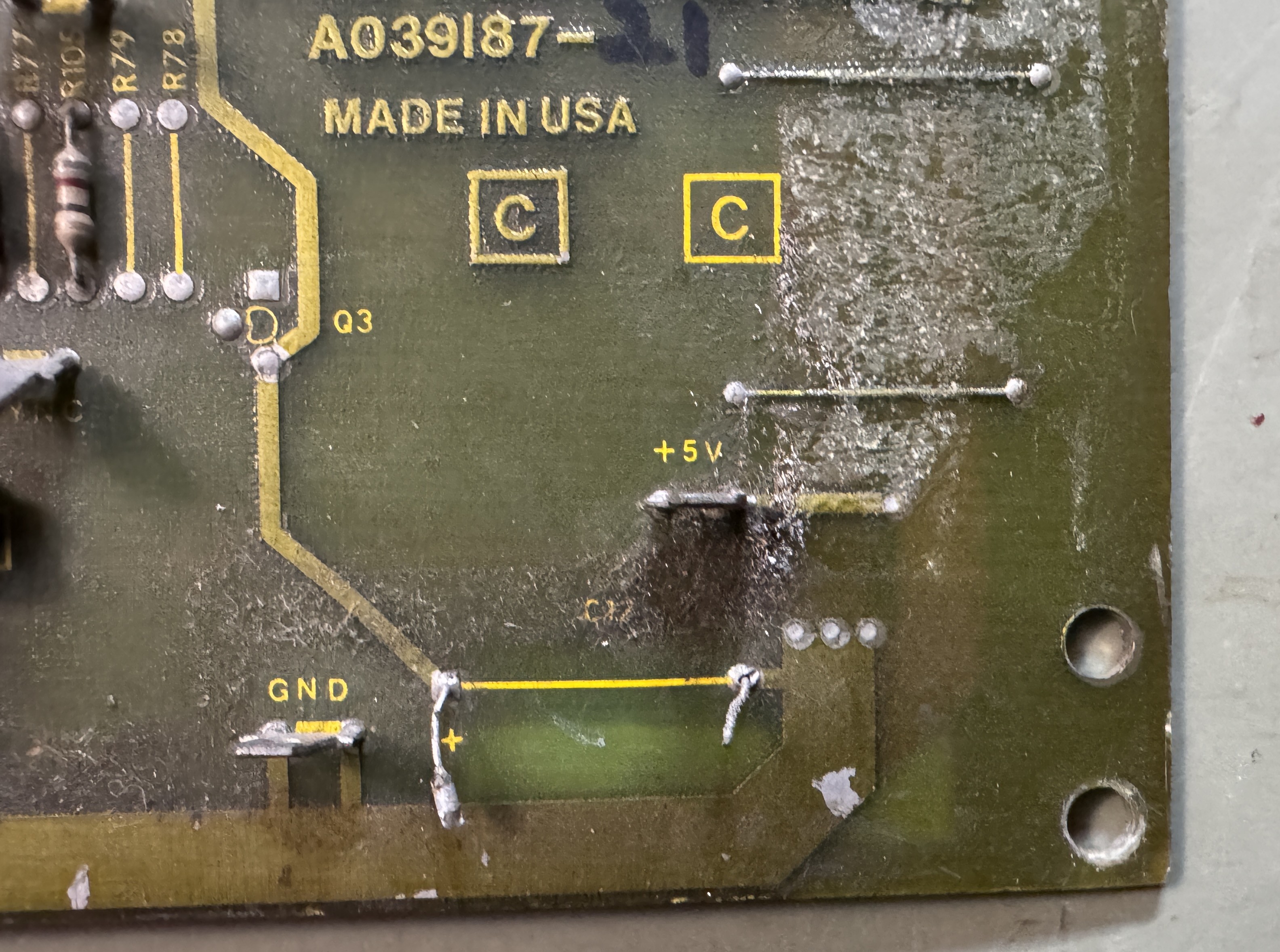
Q3 was showing an emitter-collector short. I pulled it out and the short was still there (20 ohms). I traced it back to this guy (C67) who must have been in the process of failing. It wasn’t in the alkaline damage.. Replaced C67.
Board works! (again)
Board #3 – Board in for repair
Board reported to boot to garbage.

Regardless of the what may be happening with this board – this is certainly involved.

Removed all of the bad parts. Surprisingly the damage had not quite reached the PROM or the Z80 socket.

First pass with the Dremel and wire wheel. Removed the majority of loose damage and got better visibility to the traces.

Cleaning and brushing with acid to counteract the damage.. CPU socket at this end had to go..

Second pass with wire wheel on the Dremel on all of the damaged areas and repopulated all of the missing components. During the process, all of the chips, 50+, were removed, cleaned, Deoxit, etc.


Chips with silver tarnished legs got ~3 minutes in Tarn-X. Rinse, blow dry and polish up the legs.
Board works!
Board #4 – Board sent in for modifications and a repair


Customer said the board worked – but he did not want all of this wiring and wanted the edge connectors fixed properly. He sent both ARII’s for testing and refurb with this set. He also said the battery backup didn’t work. The CPU edge repairs were pretty good, the video board edge repairs were not. The wiring all over the PCBs is useless.
I removed all the wiring and cleaned 64 socketed chips and washed the board set. Because Pole Position doesn’t test ALL of the ROMs, I check those against the database to be sure there are no bad ones..

Even when the boards look clean, they are often pretty cruddy. Washing them helps clean the contacts on the sockets as well as just getting the layer of dirt off.
Removing the prior work on the edges

They were pretty ratty below the trace replacements


Once I removed the loose metal, I cleaned the area with a fiberglass pen and alcohol. I use a UV Resin that does a great job filling in these imperfections. Cures fast and hard. Sanded out the surface with a block and made it flush with the PCB surface. My end goal is no divots or lumps under the copper and the end result is a flat repair of the PCB substrate.


Lots of careful work replacing the copper. The material I use is just slightly wider that the original fingers. It needs to be trimmed for proper spacing between the pads. If it’s too narrow – the edge connector can straddle two connections and burn something up. Final step is some liquid tin to coat the exposed copper and reduce the chance for oxidation.
Once everything was set after hours of prep..

Board started up – that’s good – it didn’t get worse. This first power on was with the original CMOS/RAM @7E.
I’ve been using these for NVRAM on Pole Position sets and the original battery damage repair had these jumpers I wanted to eliminate if possible, if they snag on something it’s not very reliable.


Plugging in the NVRAM – board would not boot. It had a memory error, really!? Yes. Turns out Vcc was ~3.5 volts when it should have been 5v. The WDDIS test point was missing from prior work, I replaced that while I was working in this area.

I traced the low voltage back to the battery circuit where VBTRY should be providing +5V+ to the RAM. Q3 was bad here. Replaced it and got +5V and the board booted correctly now, no RAM error – great! Except…..
In DIAG mode, it powered on every time stating “HIGH SCORE INITIALIZED”. This is a normally a multi-step process. Put in DIAG mode, press gas pedal, shift from LOW to HIGH. Then you should get the message. Everything would work properly once powered up. You could play, set a score, go into DIAG mode and back out. Only power cycling would cause the score table to reset.
Luckily with a little research – I found that the high score table resets when it gets corrupted. It has a checksum that gets validated on powerup. There was a thread on KLOV that mentioned this and an Atari Bulletin on the topic. CR6 diode tested correctly in circuit, but was failing as a Zener Diode (it seemed) Replacing it fixed the HIGH SCORE table being reinitialized and scores are now retained after power cycles.
This worked for the first 2 days of my test cycle which is spread over a 6 day period.
- Day 1 – Powered up for 12 hours. No issues
- Day 2 – Automated power cycle test. 30 minutes on, 60 minutes off. 16 cycles (i.e. 24 hours) no issues.
- Day 3 – Powered up for 12 hours. I ended up back in the “HIGH SCORE INITIALIZED” zone…
From here I proceeded to go over the RAM backup circuit and document all the voltages vs. a good board. Replaced the 2N3904’s. Verified everything in and out since this was a battery damage area. Everything looked good.
My next thought was maybe legitimate corruption?

The 6116@7E is where all the trouble is happening. I tested every pin in/out. All seemed to be working. I replaced the Atari single wipe socket at that location, no difference. Swapped the 08@8H, no change. Tried a different NVRAM, no change. One big clue proving it wasn’t power related (in hindsight) was I could reset the board while powered on and it would still reinitialize the NVRAM. I had a little battery damage distraction going on here.
PAL-3@7C – Pin14 is undocumented on the schematics I was using. I followed it and it is actually CMOSRAMCS1 going into the RAM Battery backup circuit. The activity on the pin was similar (but not the same) as a good board. There seemed to be extra flashes of pulses on the scope, but the primary signal was good. I socketed and replaced the PAL, no change.
I was running out of reasons here.. The only thing left was the Z80 itself. Board was running perfectly, no other issues.

Not even sure what made me try it.. Swapped in a new Z80. Problem solved. They never make sense until they make sense.
Board works!
Board #5 – Board sent in for repair

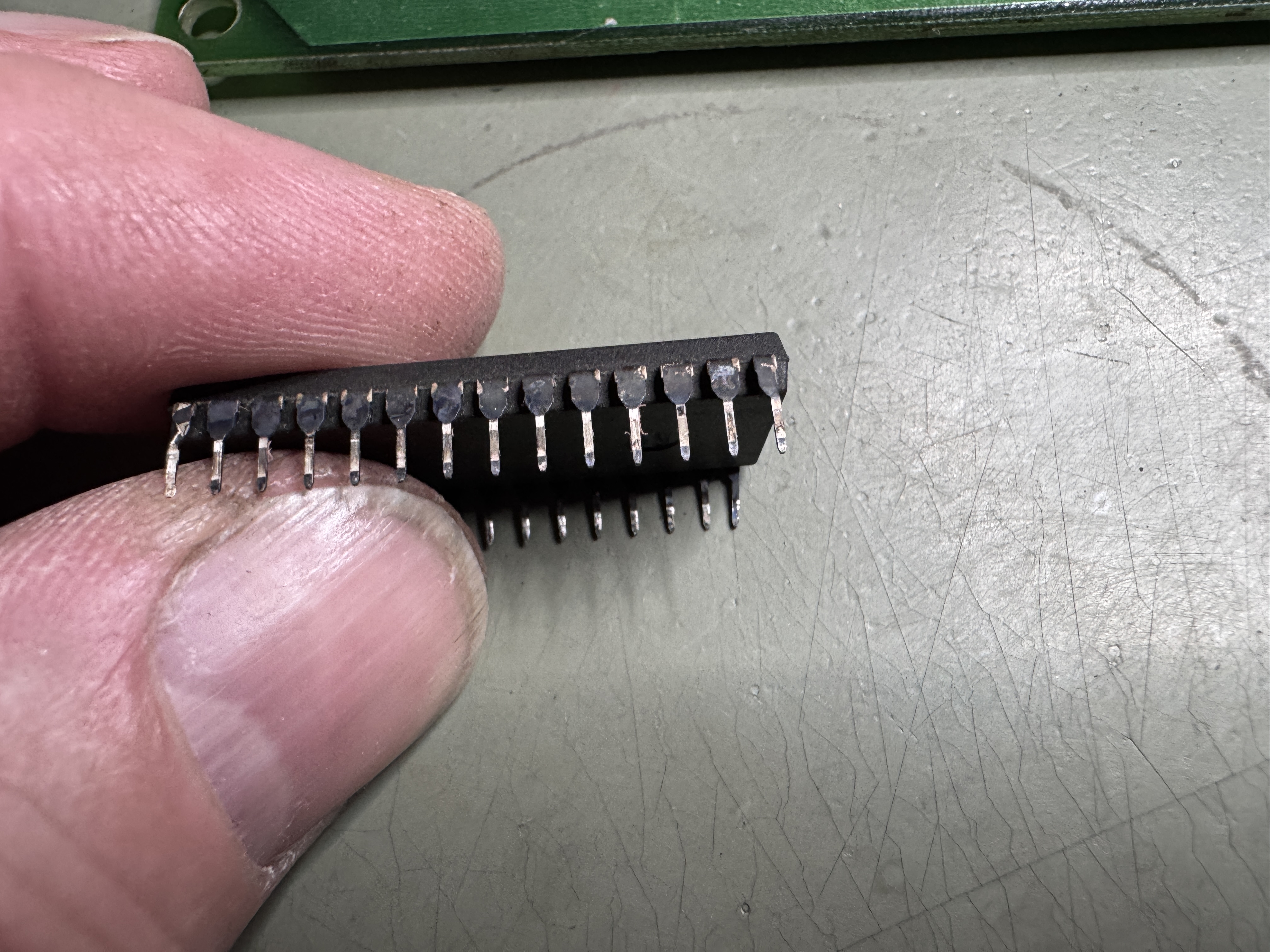
Pole Position has a LOT of chips clean, 50+. Many of the Namco custom chips had silver coated legs and they have severely tarnished over the years. Those get 3 minutes in Tarn-X and the legs get cleaned like any other chip. Often the legs are very brittle and break off – I rather this just happen now. The tarnish eats the original metal. I’ve covered this before – but I solder on new legs unless too many are gone. I repaired 10+ legs across all the custom chips.
I also wash Pole Position sets. First is to get rid of any surface battery damage. I’ve found Krud Kutter also does a good job of cleaning the exposed areas of the sockets. They start dull and often come out shiny.
Another time consumer on Pole Position sets is not ALL ROMS are tested by the self-test. It is possible to have corrupted graphics on an untested ROM. I download all ROMs and check them against the database.
Once the boards were back together – I divide and concur. Tested the video PCB with a known good CPU PCB. Video board came back to life! That’s a good start.


Here is a before / after of the battery damaged area. I’ve also shown this before. This is a multi-step process. First I scrape all of the solder mask away revealing the alkaline and copper traces. I then use etching acid to neutralize the damage, wash and wire wheel the effected areas as much as possible. Wash again and then I use some liquid tin to protect the copper. Some areas do not always coat. But this is a better situation than this board was in ..
Z80 socket got replaced to start.
Once I powered up – the majority of the board set was working. Sounds and voices were missing. Spent some time testing and verifying parts of the sound circuit. I started using the DIAG mode, but checking the voice and the engine is best done in game mode. After getting both of those circuits working it took a while to verify all the missing sounds were bad due to a bad PROM.

On the early revisions of Pole Position – they used a PROM@7L as part of the sound circuit. Later releases use TTL chips.. Unfortunately this PROM was bad.. Replaced PROM.

Board works!
Board #6 – Board sent in for repair

This is the cleanest Pole Position I’ve ever seen. At some point very early in its life, someone removed the battery and put a lithium battery in its place. It still reads 3.6v. There is no battery damage.
Board was reported to have graphics issues, then it stopped booting.. This one also had edge connector damage.

The video board had a burned up finger, all of the fingers had ben scraped up and sanded down to copper for the most part… When I repair the fingers I remove the bad metal and fill the divot with UV Cured Resin and sand it smooth.. Doesn’t take long and creates a solid surface.


Once the body work as been completed, I use copper tape and finish with Liquid Tin. It coats all of the copper and provides a small bit of added protection against oxidation.. It definitely makes the edge look better.
Now that I could power it up, it was pretty much dead.. no real activity.. Next the time consuming part… removing 50+ chips, cleaning the legs, Deoxit, reinstalling them. Takes a couple hours.

After power up and reseating a few chips here and there I got to the reported issue – roadway graphics corruption. I hunted around a while to determine the cause of this one. One additional item I do on PP is bench test all of the ROMs not picked up by the self test. Which is 18 ROMs.. I was reasonably sure they were not the cause of this roadway issue.. I probed around with the scope a bit but nothing was jumping out, then I went to a ground probe and just started ‘looking’ for the area that controlled the roadway by grounding output pins..

At some point I found myself here and the LS157@4H – grounding pins messed with the roadway in a way that made sense. Pin7 seemed to be always low.. Quick piggyback with a new chip and pin7 lifted showed output – poor mans comparator is fast and easy.. Replaced LS157@4H and the roadway was fixed. What I didn’t notice while looking at the jagged road..

All the cars had flats and the signs sorta changed size depending on where they were.. More probing around.. I spend a fair amount of time in the schematic looking at the ‘Picture Memory (Signs and Cars) page.. the issue was not there.. Poking around different parts of the circuit I was able to split cars vertically by grounding pins..

Then I found myself here.. Poked a few of the SIZE and LINE signals and got the car to change shape horizontally.. Used the scope and found LS373@11M Pin6 had a bad signal coming out. Replaced it repaired all the flats on the track!
Board works!
Board #7 – Board sent in for repair

Pole Position – here is were we started. Booted to garbage and watchdogging. However – this is one of the cleanest PP sets I’ve ever seen in terms of no battery damage and hackery..

Zero battery damage. Board has seen work over the years.
Initial observations:
- Power LED on CPU board was dead (and loose)
- Finger edge connector needed to be repaired
- Customs were tarnished
- The Z80 and one of the Z8000’s were swapped
The edge needed some work. When the fingers have solder blobs or are fat from layers of repairs – I will not put them into my test rig and ruin my connectors. Usually they are not reliable that way..
Here is how it started, didn’t look too bad at first…


These had been sanded down to the bare copper and the second finger in was really thick. Peeling it back revealed some of the original finger and the fiberglass. It wasn’t as secure as it looked.

The opposite side wasn’t much better. The copper tape was down inside a divot in the board. The process I use is to remove all of the old damage and clean out the area with alcohol and a fiberglass brush. Then I use UV cured resin to fill the area. I scrap and sand it down to the original shape.

Divots filled and flattened. Last step is to retape the repair and the clean and coat with liquid tin.

Once I got the edge repaired I got the game to boot. The cars were vertically sliced up along with other graphics issues.. but progress had been made.

Here begins the 3 hour process of removing every socketed chip from the CPU and Video boards, cleaning all the legs and testing each ROM chip. Pole Position only tests a handful of ROMs on the CPU board. All the others ‘could’ have issues. I did find one that needed to be replaced.

Here is the tarnish on one of the custom chips – needs to come off..
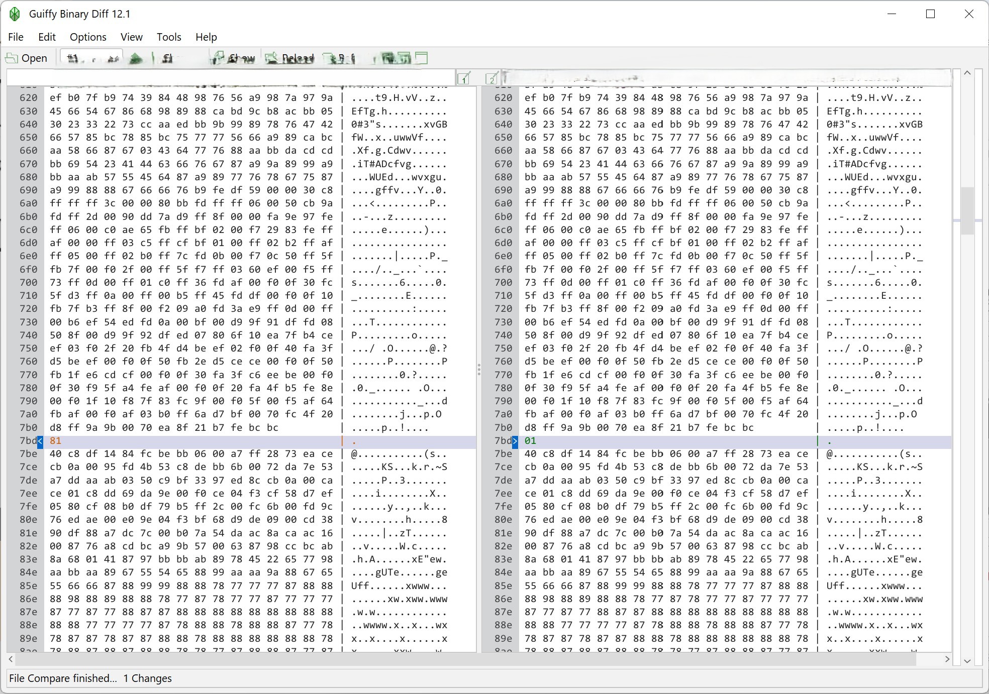
Here is a ROM that had a single bit flipped. Maybe it would not have been noticed.. or maybe it could cause a real issue.. But it got tested and caught. 23 ROMs got tested.
Back on the bench – it had issues maintaining colors.. They were phasing in and out. The road was messed up. I traced these to color PROMs that had been removed at some point. The legs were really short because they were originally soldered to the board. The repairs were done with machine pin sockets and the proms were loose and falling out.. Pulling the sockets and replacing them with dual wipes is a real pain.. Machine pin sockets are too big for the vias.. A lot of time was spent replacing them and getting things going again.
After this the board has run solid through all the test cycles. During my final checklist – I noticed I could not get the display to show MPH .. Turns out DIP switch 7 on the bank@9L was bad.. It is the mph/km switch.. replace the dip switches. Also replaced the bad Power LED.
Board works!
Board #8 – Board sent in for repair
The last board was in excellent condition except for the edge connector. This one looks like it just came out of the box. Not sure if I’ve seen a board without even discolored edge fingers.

Battery much have been removed 40 years ago.. Even the battery jumper W1 is pristine..
Upon first power up..

This was it.. stone dead.. The Z80 was bad.. Replaced the CPU and got some activity.

This screen had some blinking at least. I connected to my tester, ROM was good, RAM was showing a failure @7J.

2149 RAM – says sound RAM but was preventing booting and scrambling the screen. Replaced the RAM and game came up. I spent the next few hours removing all the socketed chips, cleaning and replacing. I also bench verify all of the ROMs since only a few are actually checked by the built in diagnostics. Added a high score save RAM per the request of the owner.


Did multi-day burn in testing.. Runs great!
Board works!
Board #9 – Board sent in for repair
Had a few of these lately – this one was sent in labeled “DEAD”

It visually had a number of issues – but the edge connectors were in reasonable condition. I removed all the socketed chips and verified all of the EPROMS on my tester. PP tests a handful of them on the CPU board – but none of them on the video board.

I few of the caps were busted or just completely missing – video C4 & C17, cpu C56. Replaced them. After cleaning chips, verifying ROMs and repairing the caps and a few other small items.
Once it was all back together – getting a board set to boot is the hardest part. Here we get through almost all of the boot process before it resets and starts over. There was no ‘crash’ sound which is standard on PP before the final screen.. That was part of the clue. On the CPU board there are 3 Namco customs, the 51xx, 52xx and 53xx. Each are involved with sounds and voice etc. I swapped some in from a known working board and determined the 51xx was bad. It had failed in such a way that it was preventing the completion of the boot sequence.
Once I got past that – there was plenty more to do. The game now booted into diag mode and reported the 6116 RAM@3F was bad. Replaced that..
Once the game is running, it is a matter of hunting down all of the glitches. Cars and signs had were messed up colors. Tracked this down to the PROM@12H (a known common failure point) to get them working properly again. While I was looking for the issue – I noticed a wrong RAM was used @10F. These are supposed to be high speed 2149 RAM. As some point someone replaced it with a 2114 RAM. The are pin compatible, but not as fast. Since they are part of the color outputs – I replaced it (which turns out caused an issue a bit later.. stay tuned)
Now that the cars and signs had proper colors.. Another graphics glitch revealed itself..

This interleaving showed itself on the logo and on the cars at certain points.. they would phase in and out depending on car rotation and position. It certainly had the look of a counter issue..

The 74S161@10H had been socketed and replaced in the past – but it seemed to be bad again. Replacing it corrected the graphics interleaving. While doing some testing, the boards showed RAM22 had died (on the video board..) except it was fine.. and the 3rd CPU would not boot.
On the CPU board

These 4 – 10xx customs often cause random errors to the video board. If you can remove, reseat or somehow get the game to boot and fail just by manipulating them – they need sockets. Visually the sockets looked fine, but this style of socket often has a crack in the leg where the pin meets the PCB. This PP set would randomly fail with video board errors.. Replacing the sockets made the game run overnight w/o crashing.
This last part was semi-self inflicted.
Look real close as you pass the yellow sign on the left – you get an interleaved version of it on the right.. This happened in a number of places and even at the end of one of the attract sequences there was an interleaved sign sitting in the middle of a field – where it would not be under normal circumstances.

It was just noticeable enough to be annoying and was just a brief flash.. Seeing that it was interleaved and it was a sign at least pointed me in the right direction.. Knowing that an interleave like this under normal conditions is RAM related..

My first thought is was that it was a chip that supported these 2149 color RAM. I pulled the RAM @9F and ran the attract mode and got regular road signs with missing lines as expected due to the missing ram.. The artifact signs still flashing in for an instant.. Next I put that RAM back and pulled the 2149@10F.. I got the signs with missing lines (as expected again) but NO artifact signs! Nice – the issue was on the 10F side of the circuit. Before I went too much further – I put the known working 9F RAM in the 10F socket.. no artifacts.. Bad RAM? yup.. I replaced the RAM that I had replaced earlier and corrected the issue. Maybe it was too slow? to fast? or just lazy.. But it was causing the interlaced sign artifacts in the wrong spot.
Board works!
Board #10 – Board sent in for repair

This one came in from a buddy who had a PP cab and wanted an original PCB. He’d been looking for a while and finally got one worth fixing. Before I could even power it on I needed to:
- Repair battery damage area
- Repair burned up edge connector on the video board (not as common, usually it’s the CPU board)
I started with the video board edge connector.


5v was a mess and had been cratered at some point. Cleaned it out and the used the fiberglass pen to sand out the loose part until it was as solid as you can get it.. Cleaned it all up with alcohol and then filled with UV cured resin. The resin sets in 2 minutes and can be scraped and sanded flush with the PCB.

Add some copper tape and Liquid Tin to complete the repair. The pics make it look a bit bumpy – but the result is actually very smooth and the same thickness as the original fingers.

The battery damage was not quite as bad as it first looked.

The ICs has a little surface damage, but seemed pretty solid. All of the resistors, transistors and diodes of the area were in pretty bad shape.

Removed all of the socketed chips gave the damaged area an etching acid bath and then wash the board, dry with compressed air and use a fiberglass pen to polish up the areas and remove as much battery damage as I can within reason.

All of the effected components replaced.. I cleaned up a bit more in this area as I noticed it. You can only make this look so good..


Here is the Z80 socket and the Z8000 socket @3A. Both were in pretty bad shape and got replaced.
An interesting item on this set.. IC25 was not a custom chip – but this small PCB instead.. Had not seen this in the past.


After a couple of false starts with sockets and a few other small issues – the board powered up and booting into diag mode, nice! Interesting item – stepping on the gas also stepped on the brake at the same time. I swapped a few customs around as an initial check.. But that was not the issue.

The 4066@8K had failed and was the root cause of the issue. Replacing it corrected the problem. Now I had a fully functioning PPII set – great! Ran first 12 hour burn-in test.. It lasted about 3 hours. Boards were stone dead. A little probing – no clock.

I started at the video board with the crystal is – clock was there. Traced back to the CPU board, clock going into the S161@6N – nothing coming out on Pins 13,14. Replaced it and board booted into diagnostics reporting a RAM22 error. I got a 2 for 1 failure. Replaced the RAM@7K on the video board.

Board works!
Board #11 – Board sent in for repair
Not the worst Pole Position I’ve ever seen, but needed some cleanup work to get to testing and repair. All of the socketed chips were removed and the legs cleaned. The ROMs were all tested off board. Many of the Namco customs had tarnished legs.

They tend to be pretty frail. I clean them with Rust Erasers and a Fiberglass Brush. During the process ~8 legs broke and needed to be repaired. Some required using the Dremel to slot the case and access the inner portion of the broken leg to attach a new one. I seal all of them with UV Resin to add strength.
The edge connector was not in very good condition.

I cut out the bad areas, filled the divots with UV Resin, sanded the surface flush and added copper tape. The last step is to use liquid tin to coat the copper and prevent it from oxidizing with time.
The board itself needed to be cleaned.


Many of the sockets were caked with crud and I used etching acid to neutralize the the battery damage. Boards got washed as a result to clean up everything.
Powered up the stack finally and just got a frozen screen. While starting to probe around, after 2-3 minutes the board suddenly started. I figured I’d hit something with the probe or my hand.. looked a bit and then realized it was a thermal issue. I powered it down and worked on a Tempest for a while.. Came back and it was locked up again.. Probing around showed it was stuck in reset.

The tricky part is I had to find the issue before the chip in question warmed up.. It would boot after a couple of minutes.. Luckily I found the culprit after a couple of cycles.. The 74LS161@6A was not working correctly. It is in the battery damage area and got replaced.
Ran it over night and it developed a graphics glitch. Look at the back of the large cars.. there is a white dashed line that should be solid and there are vertical lines at the back.. ROM119 (a mask ROM) went bad during testing. After replacing that..
Board works!

great summary and another board saved.