
A repair shop that I’ve done some work for asked me if I would take a look at Sprint 2. I’ve only worked on a few bronze age games. One thing about them is you can see how the golden age games evolved from the earlier ones. Ex: All of the power conversion and regulation happens on these early boards. Atari creating the ARI and the ARII did a couple of things.. removed a common failure point (power) from the logic board and freed up real estate for more game logic. There are a number of things like this I noticed and a number of ‘experience points’ gained.
Fortunately the repair shop had 4 boards to send me.. A working reference board (it didn’t immediately work btw). Their customer’s board and 2 more they had that I could use as parts boards or preferably have me fix them too.
Sprint 2 is one of the first mass produced games to use a CPU. It has a 6502 processor. This was in 1976.. I was teaching myself 6502 assembly language on a Commodore 64 in the early 80’s.. That is a long history for a processor by todays standards.
Working on these was a bit of a blur .. figuring out how it worked and some of the quirks slowed me down here and there..
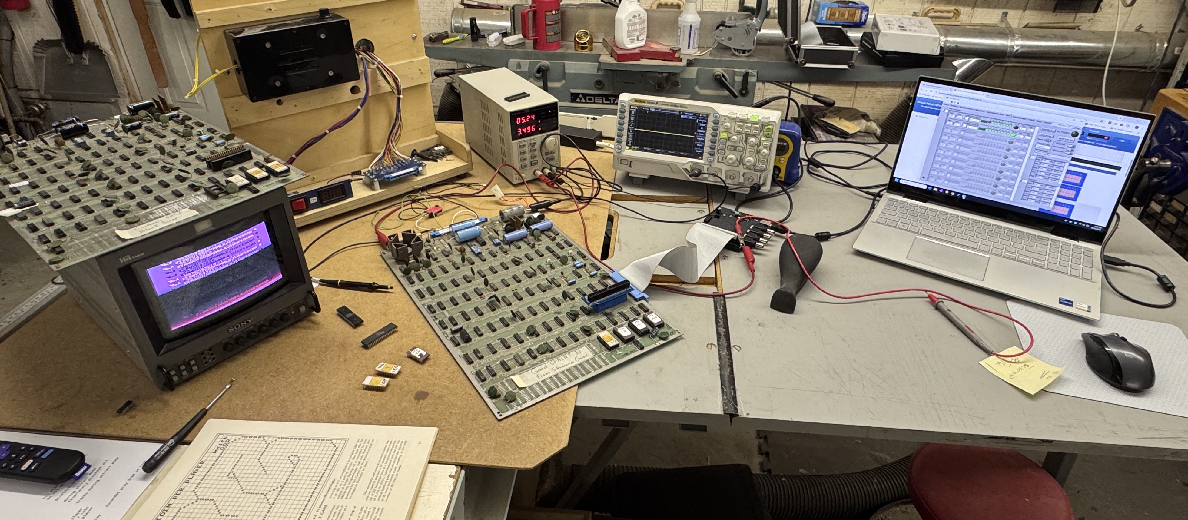
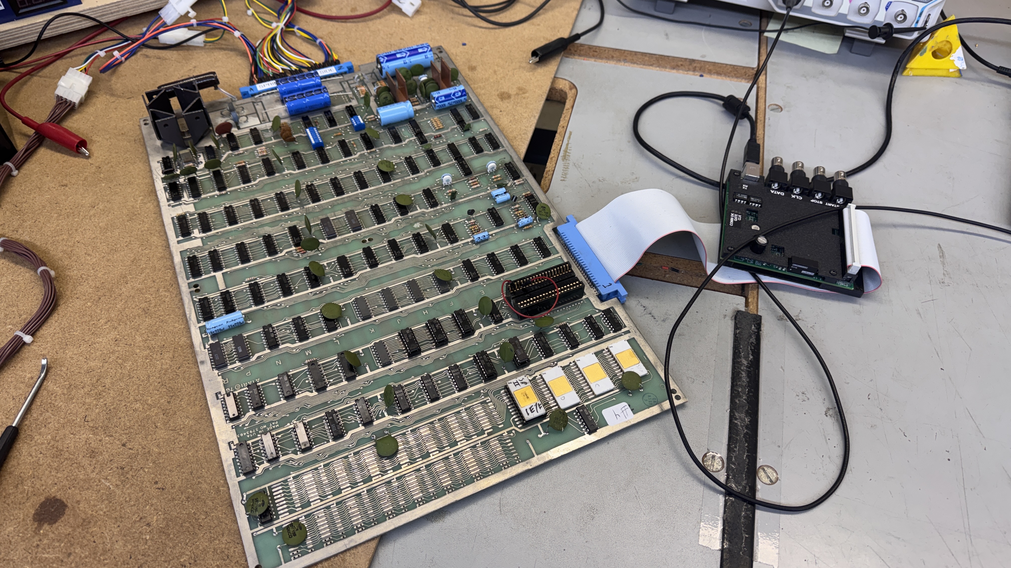
First up was getting something on the screen – which requires a bench harness. I wasn’t able to use my regular test rig (easily) so this is more of a one-off test harness than usual.
It started real simple – 5v+ connected from a bench supply and a composite video cable. I’ll show the completed harness here, but this happened after getting the customer board working to the point where I needed ALL of the controls to continue testing..
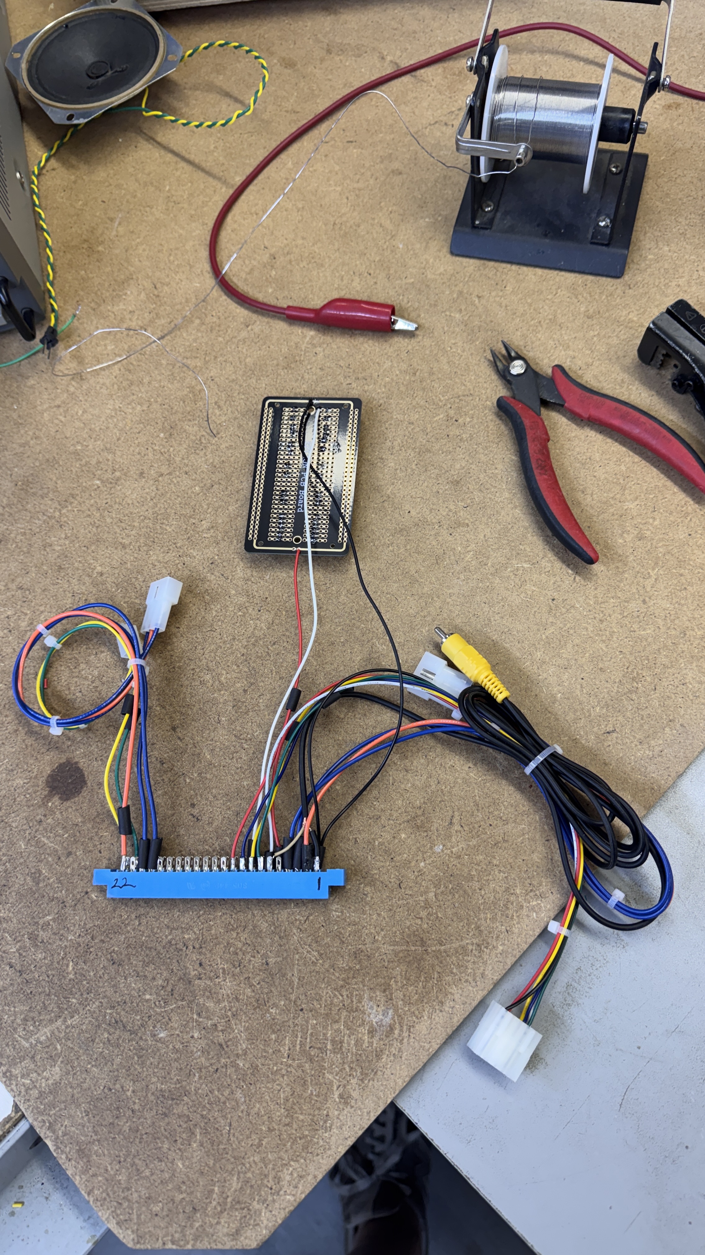
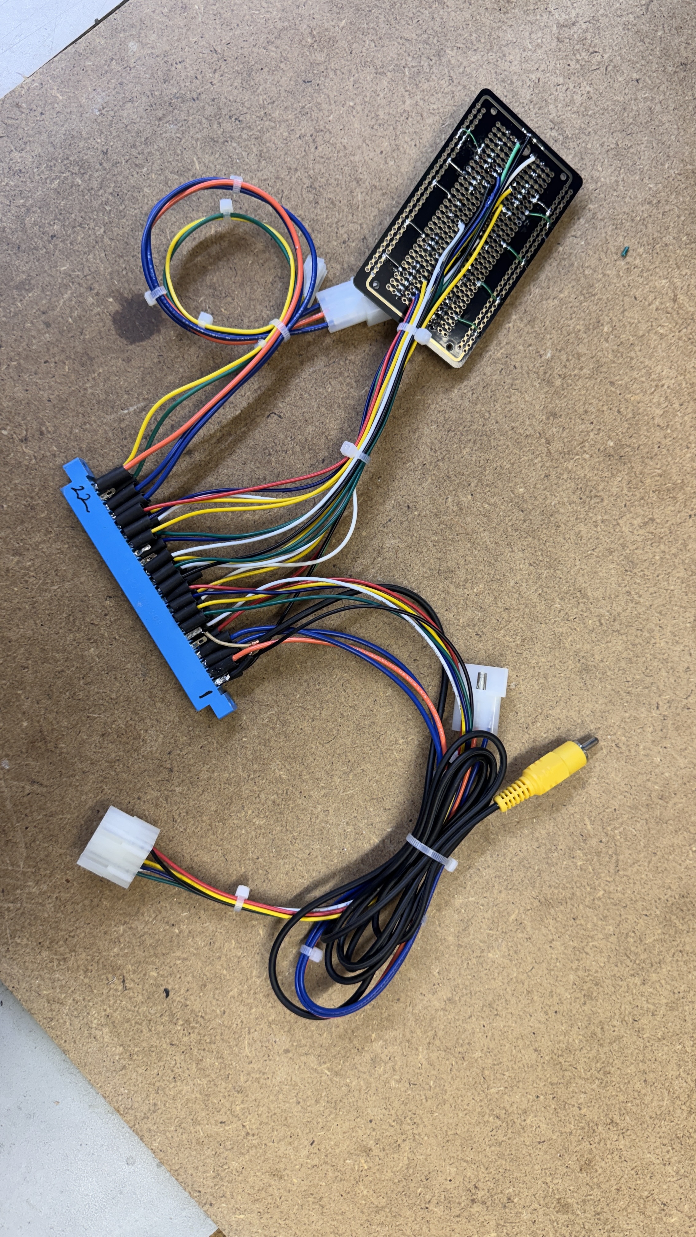
I’d added connections for center tapped transformers to make sure the on-board power regulation worked. The bench supply got used for the 5v+ in the beginning, but I’d found a situation where I wasn’t easily able to work around not supplying AC to the board. The AC setup works well enough and I had an old Pacman transformer that works great. My trackball is used for steering.. Horizontal for the white car and vertical for the black car. I can’t drive 2 cars at once anyway, I just need to know they work.. All of the other controls took a few hours to get wired up and debugged. Good thing Amazon exists.. I was able to get some switch assortments to make up all of the bits I need to test with..
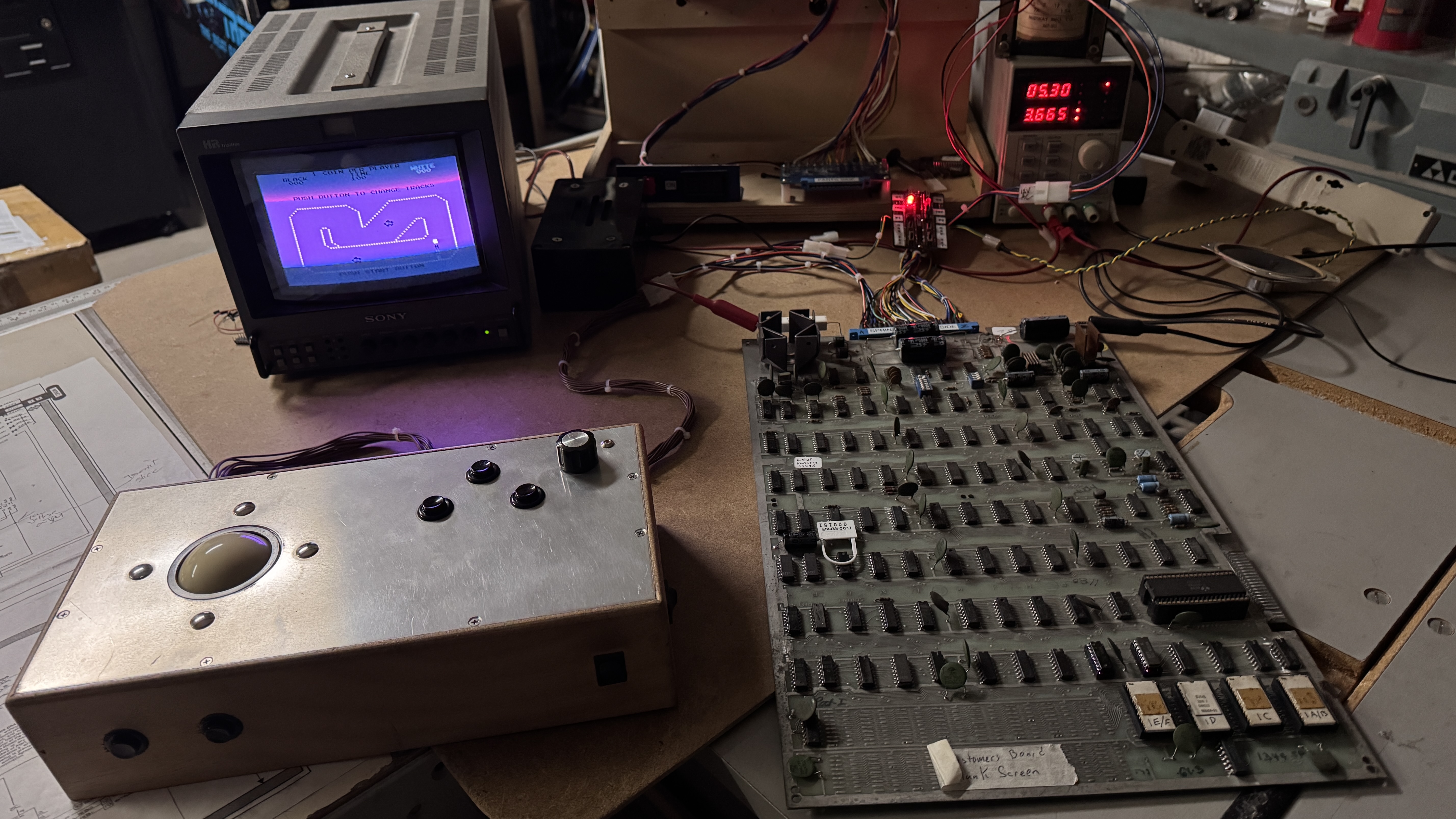
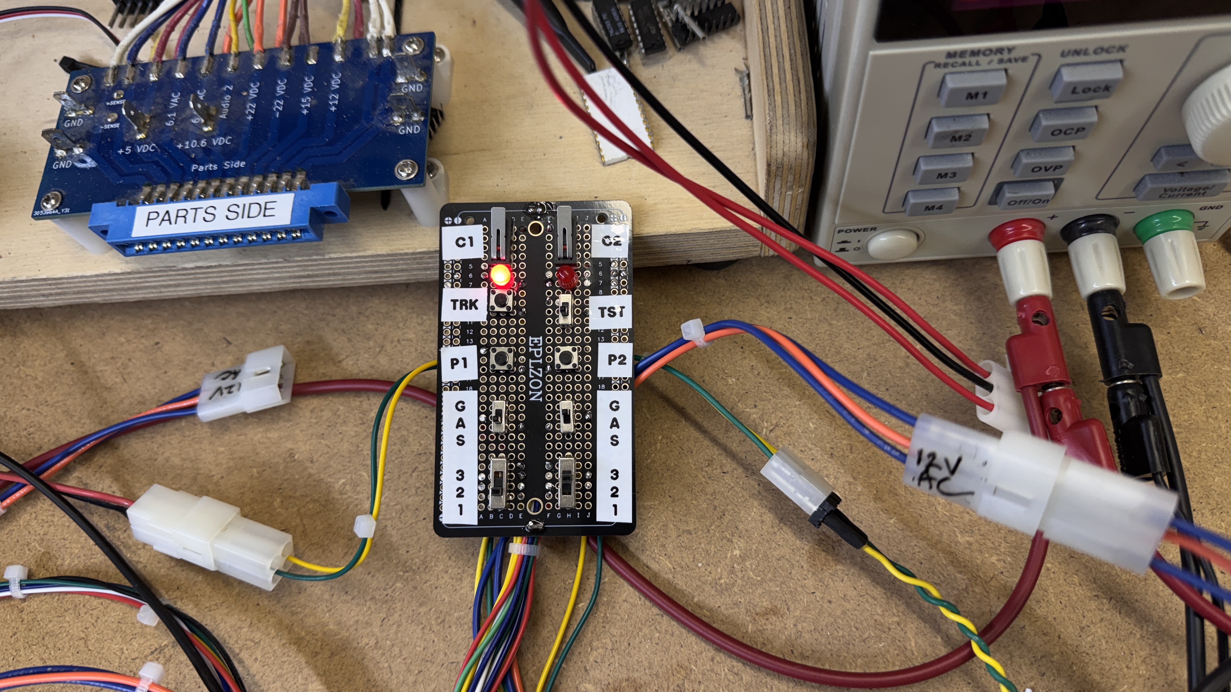
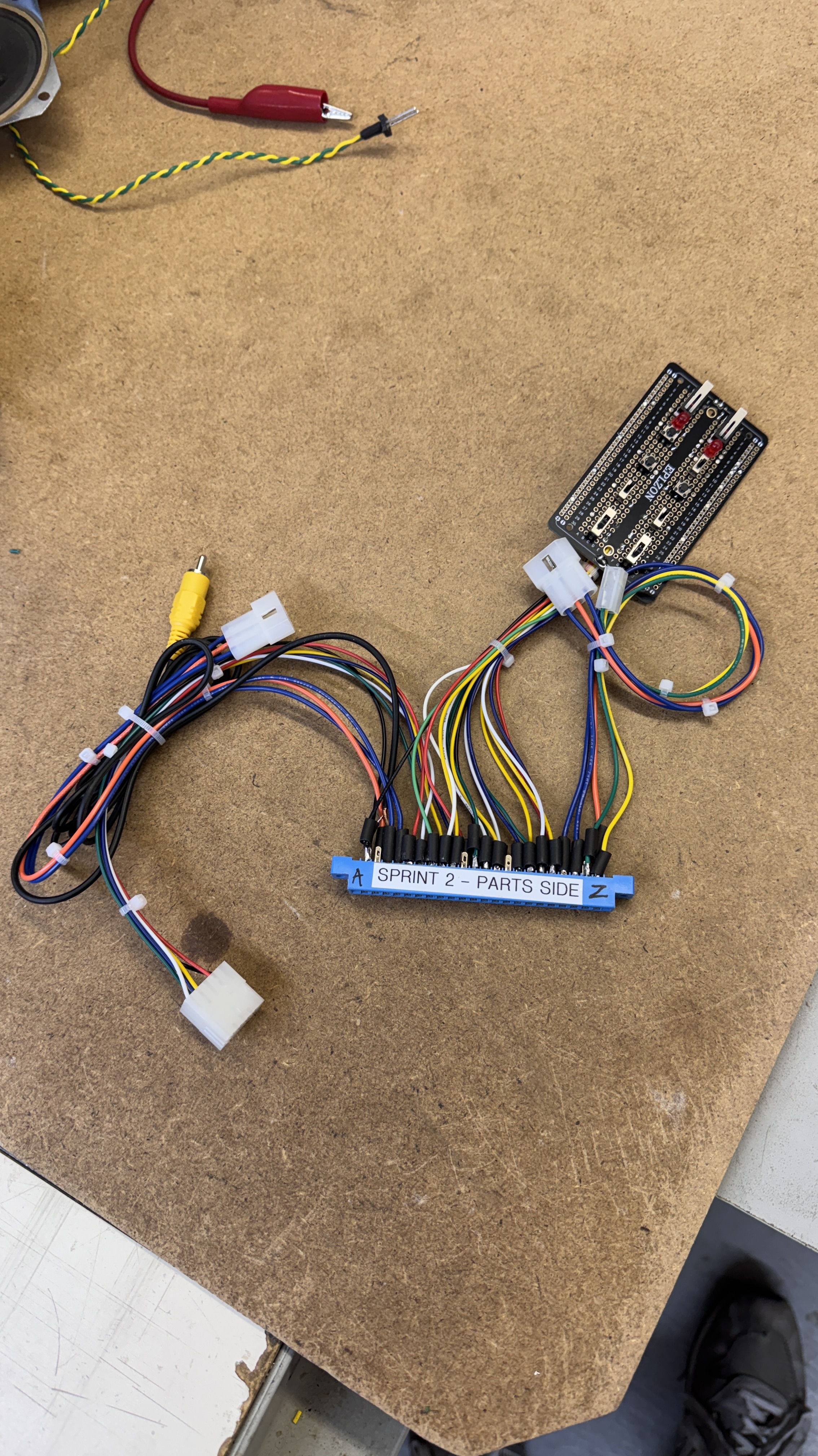
Trackball for steering – small CP for Coin 1,2 Track select, Test switch, P1/2 start, gas pedal (on/off on this game) and gears 1,2,3.. 4th gear is all switches off. The kit did not have a switch for that.. but if 1,2,3 work (all 1’s) the 4 will work since the 0’s work in the first case (hope that makes sense).. All game functions now accounted for..
Board #1 – Reference board
This one was sent as a ‘working reference’ but didn’t immediately work – in the end it just behaved differently than the other boards (+a couple of glitches) I did not work on this one first.. I spent the majority of the time working on Board #2 before coming back to this one.
When I finally came back to it after getting the harness all sorted out, it locked up when a credit was added. The screen just froze and the credit LEDs did not light. It also locked up if I put it into free play.. this seemed like a software issue of course.. I retested the ROMs.. no problems. I even started reading source code.
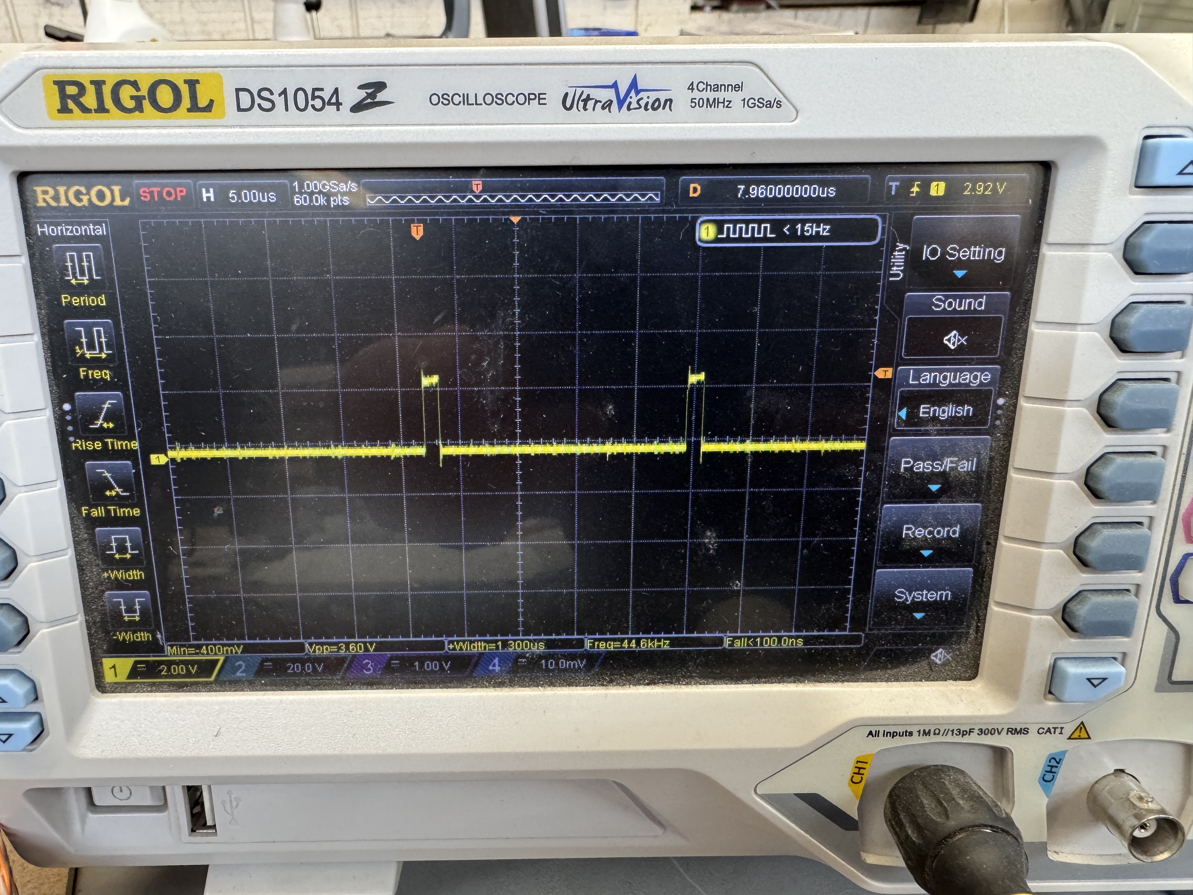
While doing all of this – I followed the watchdog to see if it was frozen or firing.. I determined the watchdog circuit was not working.
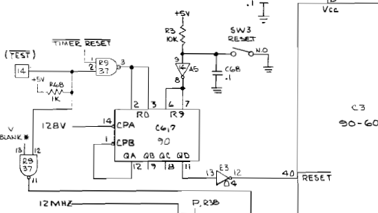
Replacing the 7437@R9 fixed the watchdog and now instead of just freezing, the game would watchdog reset when a credit was added or I put it into free play – that at least made sense. Attract mode and even test worked correctly with all of the switches working as expected.. Somewhere along the way the source code made me want to look at this area..
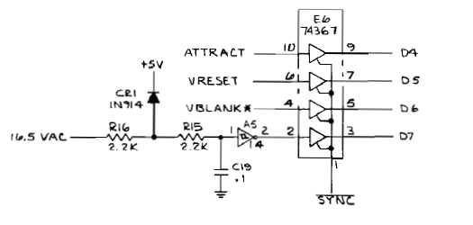
I ended up comparing this to a working board. The input on @A5 Pin1 was ~4.3vdc on this board that locks up and ~1.3vdc on the working boards. The difference in the voltage caused the output on Pin2 to flip from high/low depending on the voltage. Keep in mind at this point I had bypassed the AC inputs and was using 5v bench power. Board 2 and Board 3 were working. I checked the resistors and replaced the diode and C1 – I’m not sure where/how the boards were different. I ended up wiring AC power (removing the 5v bench supply from the equation) and board stopped crashing when adding a credit. I’m not really sure why Board2,3 work since with AC power, the output @A5 pin2 is a 60Hz square wave when connected to AC but it is a steady 5v when connected to DC. The code definitely does not like D7 being low when adding a credit. I didn’t really figure out what the purpose of that D7 line was..
During all of this I also found that the 4 ohm/10W resistor across the voltage regulator was flaky. The resistance would change anywhere from 14 ohms to 90 ohms just by hitting it.. That got replaced.
Board works!
Board #2 – Customer board for repair
Board came in reported with no video.. After getting the minimal bench adapter set up and the power figured out.. plugged it in .. no video.. and no clock to speak of after probing around.
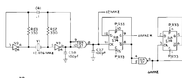
Bad 7437@R9 – no clock – no video. Replaced it.
That is what got me to this point.. something to look at.
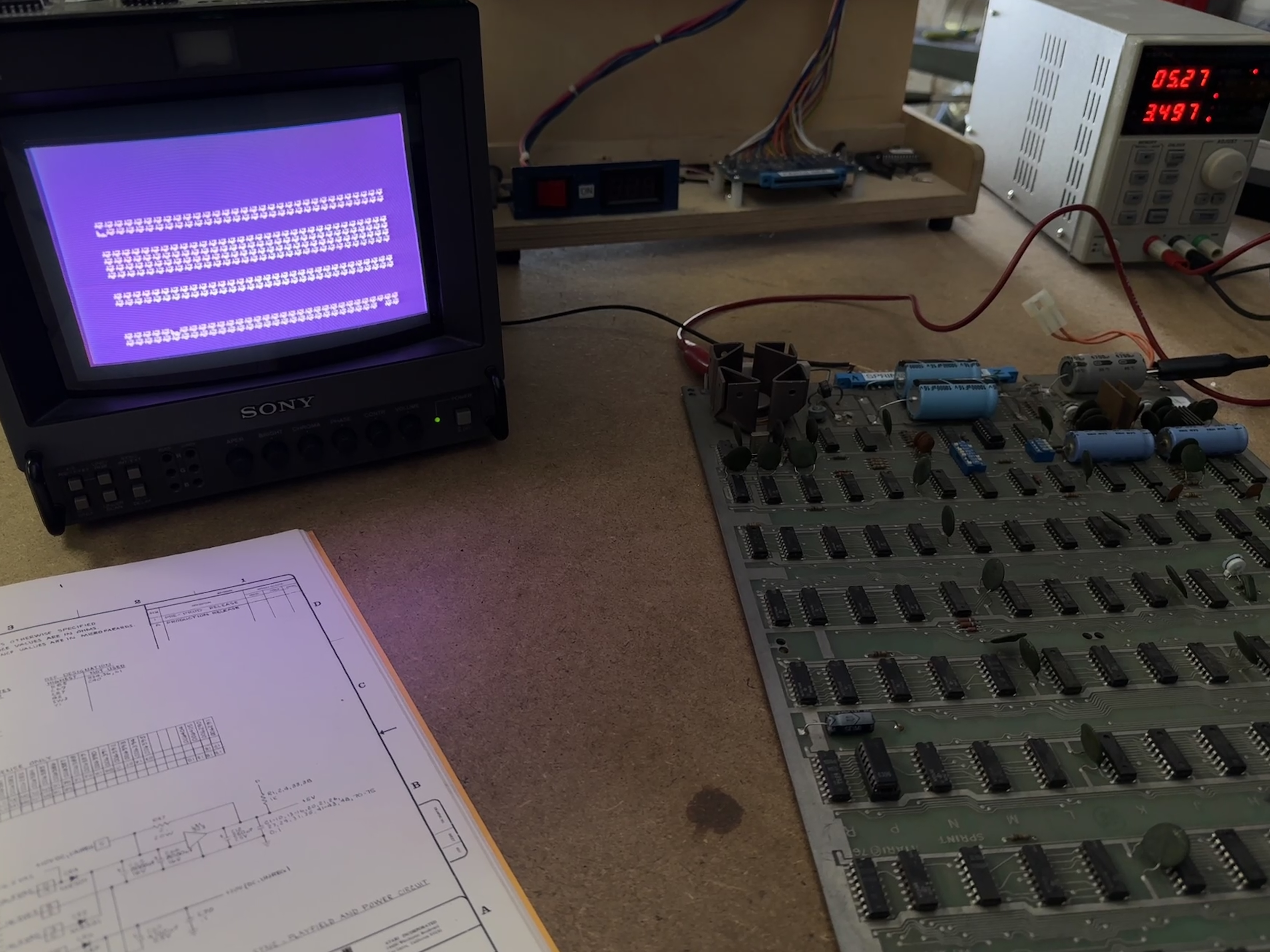
Figuring out this board took the majority of the time as almost every new board (to me) does.. I was able to create a Tester config that could verify the RAM and the ROM. The lower half of the RAM appears to be mapped/used differently. The D7 bit never verifies on the lower half of memory. All of the boards behave the same in this respect. Using the sequential test I could get the ascii characters to display full screen.
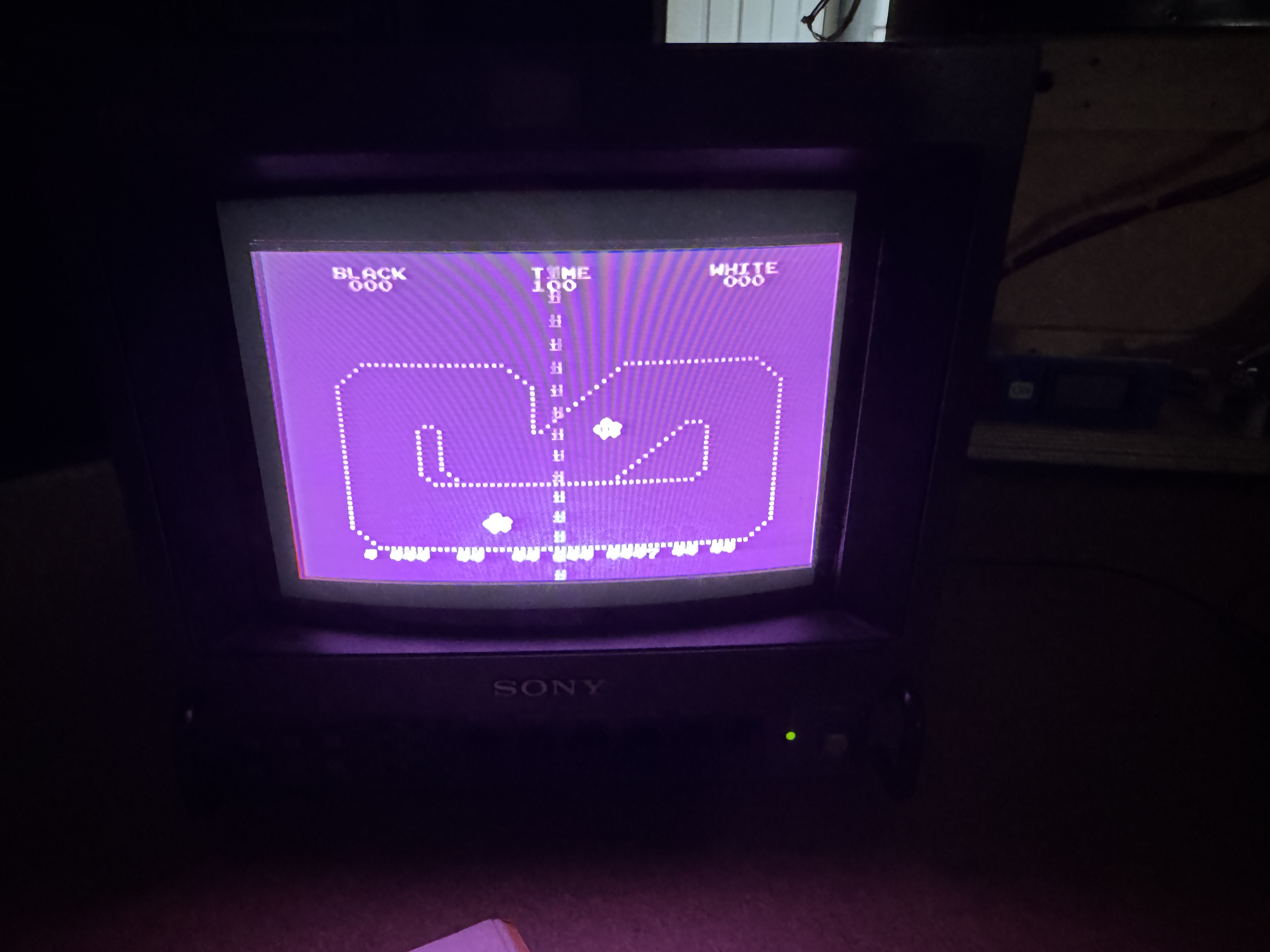
Trying to get the game to boot – that did not work. Even with RAM/ROM verifying. I could get this screen and a set of stacked cars that would blink down the center of the screen.
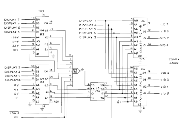
The 7483@M4 was part of the issue – the 174@L5 had a floating pin5. Together these fixed stacked cars. Still, this board wasn’t booting. It would display most of the screen and just stop.
7400@D0 did not seem to be driving enable on @1C, 1A high enough, even though the ROMs tested good on my tester. I replaced it and the new chip drove the enables better. But it was not the issue.
Along the way – the RAM test was still working correctly but the video output failed. I’m now going backwards.
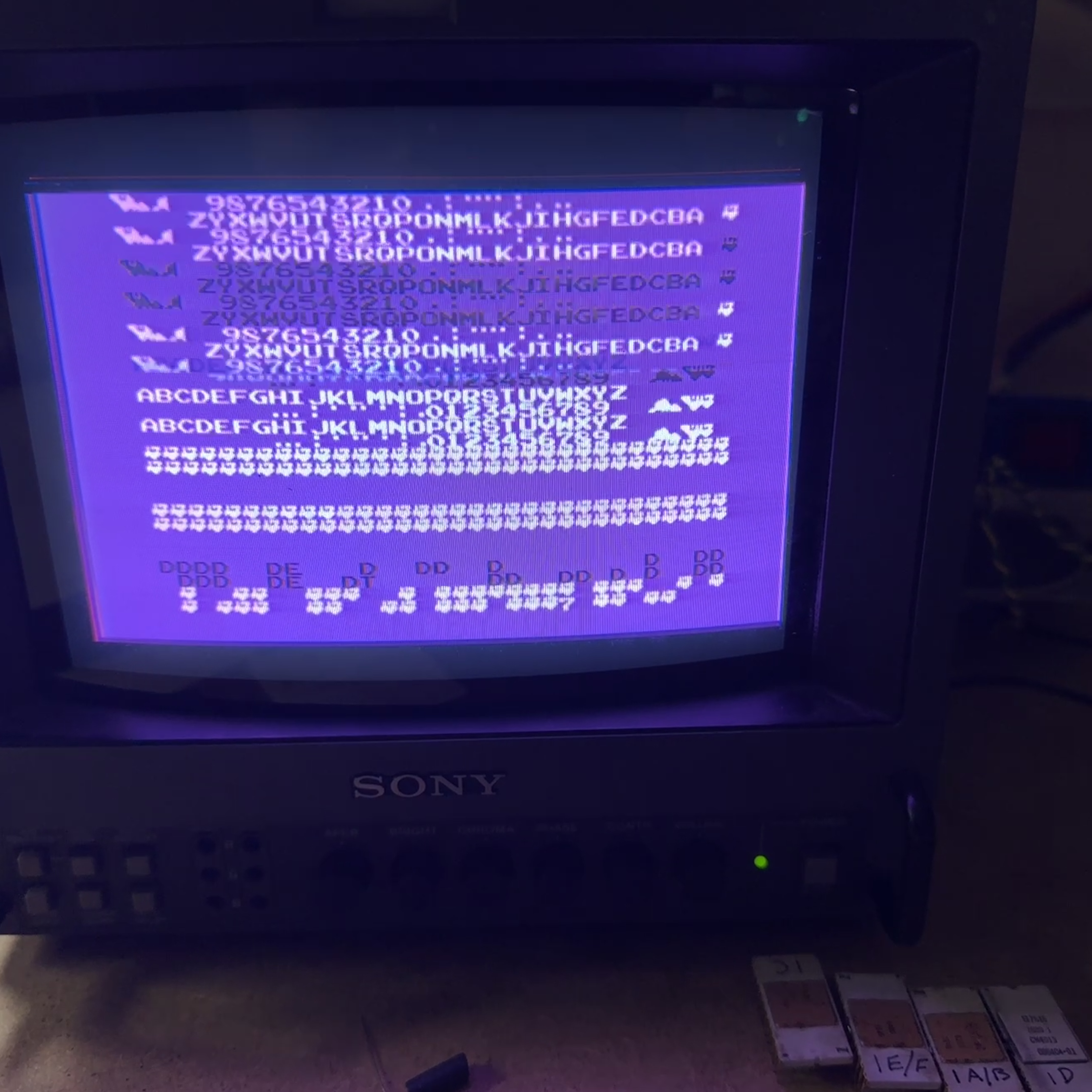
This screen should be fully repeating character sets vs. garbage at the bottom half. The PROM@2E had failed. I borrowed one from Board 4. Thankfully it is a 82S123 and I can get one burned.
Here is where I kept going over the board and didn’t understand why it wasn’t booting.. Boards 1 and 3 were testing good RAM/ROM the same way and didn’t even put up the dead track screen. I was missing something.. I closed up shop for the night and woke up with an idea. I was 95% sure it was the answer. Surprising how well ‘sleeping on it’ works..
I blame the Bronze Age…
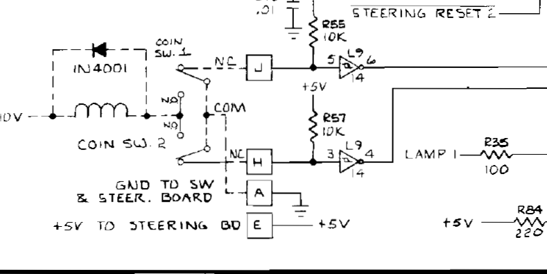
Early coin switches. On Sprint 2 it is normally closed AND pulled up to 5v+. I had connected a micro switch to Coin1.. But didn’t do anything with Coin2.. After jumping Coin2 to 5v+..
Well looky here.. Game boots. Not having Coin2 pulled to 5V made the game logic think that it was stuck in the add credit code. i.e. it froze the screen. This board displayed some of the screen before freezing. The other boards stayed at garbage and I never saw the track. I’m betting in the early days this was a real pain. If you had a machine on location and a simple coin switch broke.. your machine was down.. The newer games are different – normally open and the switch pulls to ground FROM 5v. A broken coin switch didn’t kill the machine.
Experience +1 – do a better job on thinking like the input logic.
Now that this game booted .. as well as board 1 and board 3.. I built up the full test controller from the top of the thread.. It has all the controls to test every part of the game.
On a roll now.. During testing.
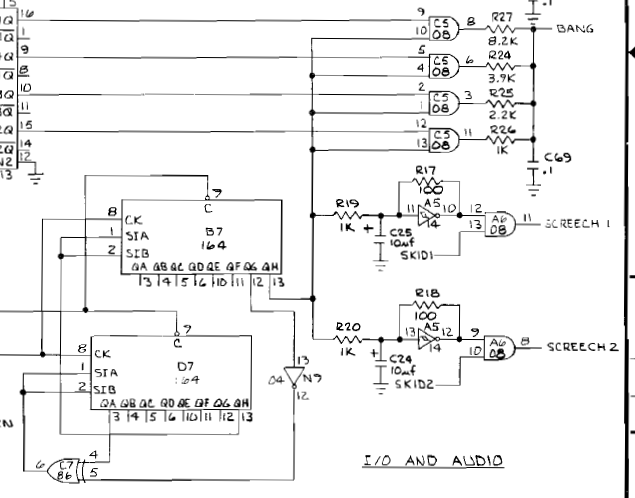
No bang/crash sound – dead outputs on 74164@B7 pin 12,13 – replacing fixed it.
A fun quirk of these early games.. No skid sound for just the black car – replacing 74279@H6 – fixed it.. The white car had the skid sound. The big power resistor broke along the way – replaced it.
Board works!
Board #3 – Spare board for repair
I used this one as a reference while trying to figure out how these worked in general. It had both of the large filter caps missing. I had to order them to get it back to working with AC correctly. The audio amplifiers were missing the heat sinks. I added some back on since they are relatively rare and expensive to replace at this point.
After verifying RAM / ROM and some board maintenance..
Board worked!
Board #4 – Spare board for repair

This board seemed to be under repair and was pretty nasty overall. At first I figured it would end up a parts board. While debugging the other boards I borrowed a ROM and the PROM@2E. ROM was good but the PROM on board 2 was bad.. This one was also missing the large filter caps, RAM had been removed and a 9301 had been removed. I wasn’t 100% sure it would be repairable/I’d have what it needed.. The first 3 boards were working at this point.
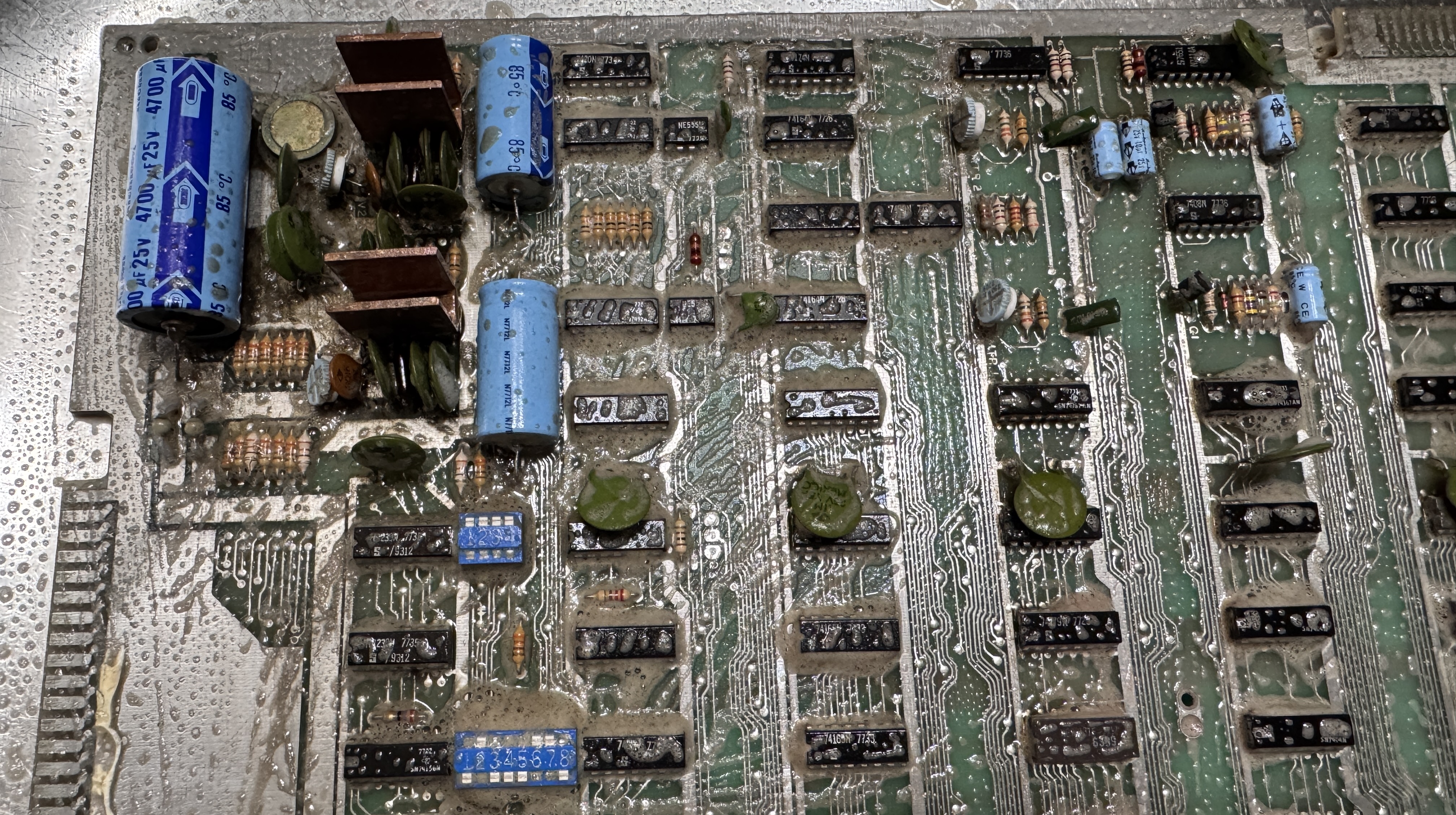
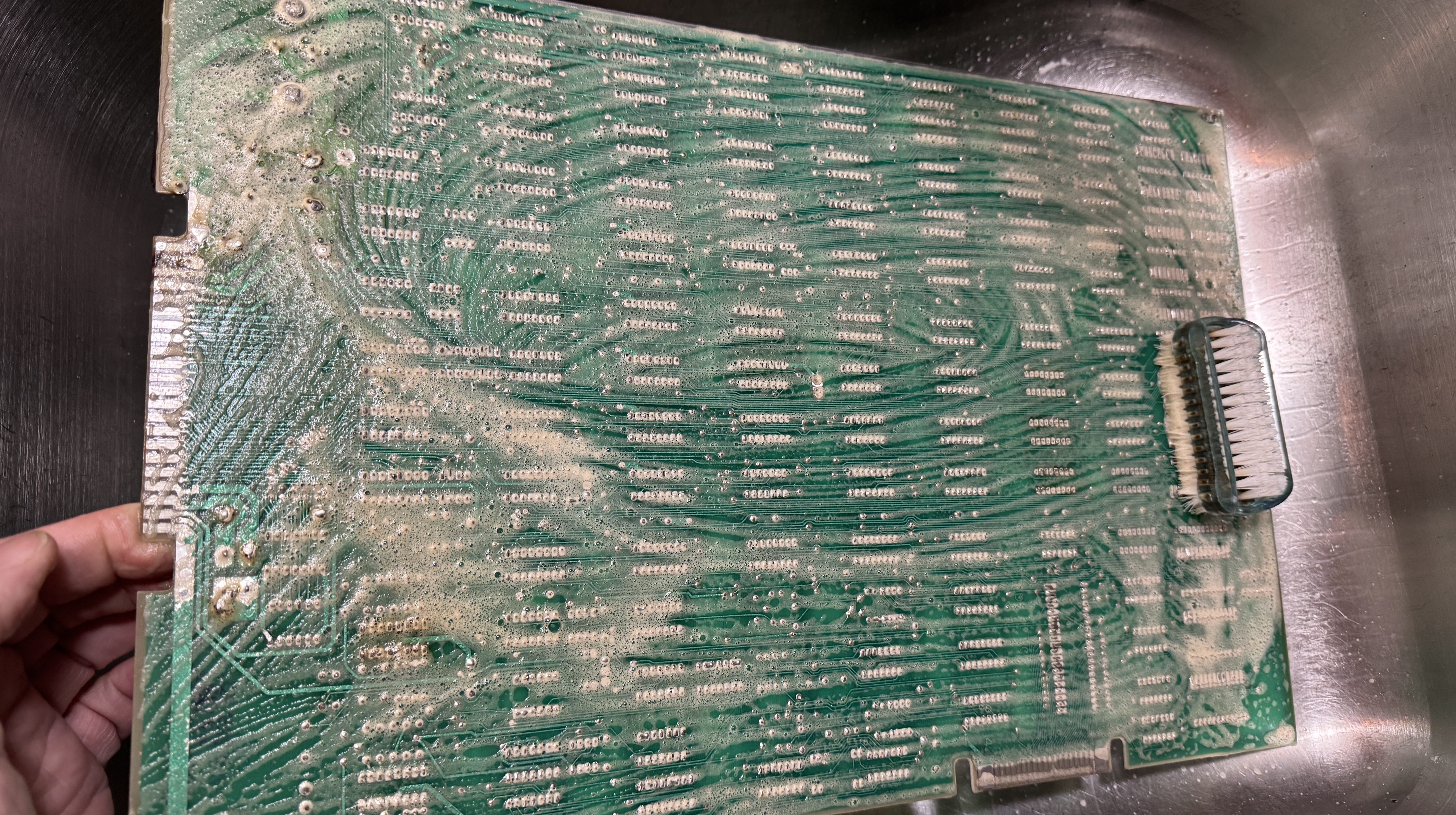
It was really covered in crud..
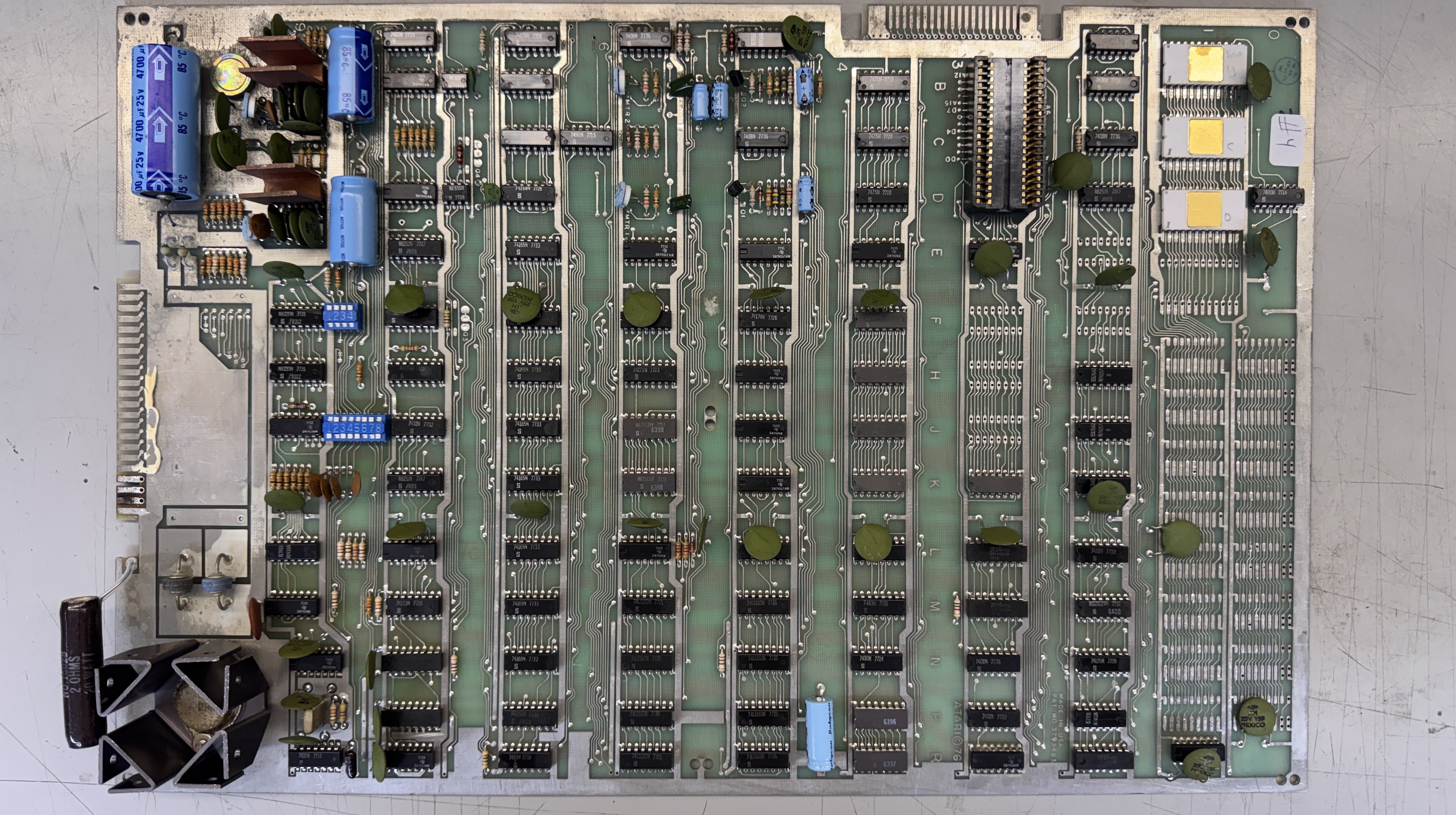
But it cleaned up really nice! One thing about that sort of dirt – it seems to protect the board from oxidation etc. by encapsulating it.
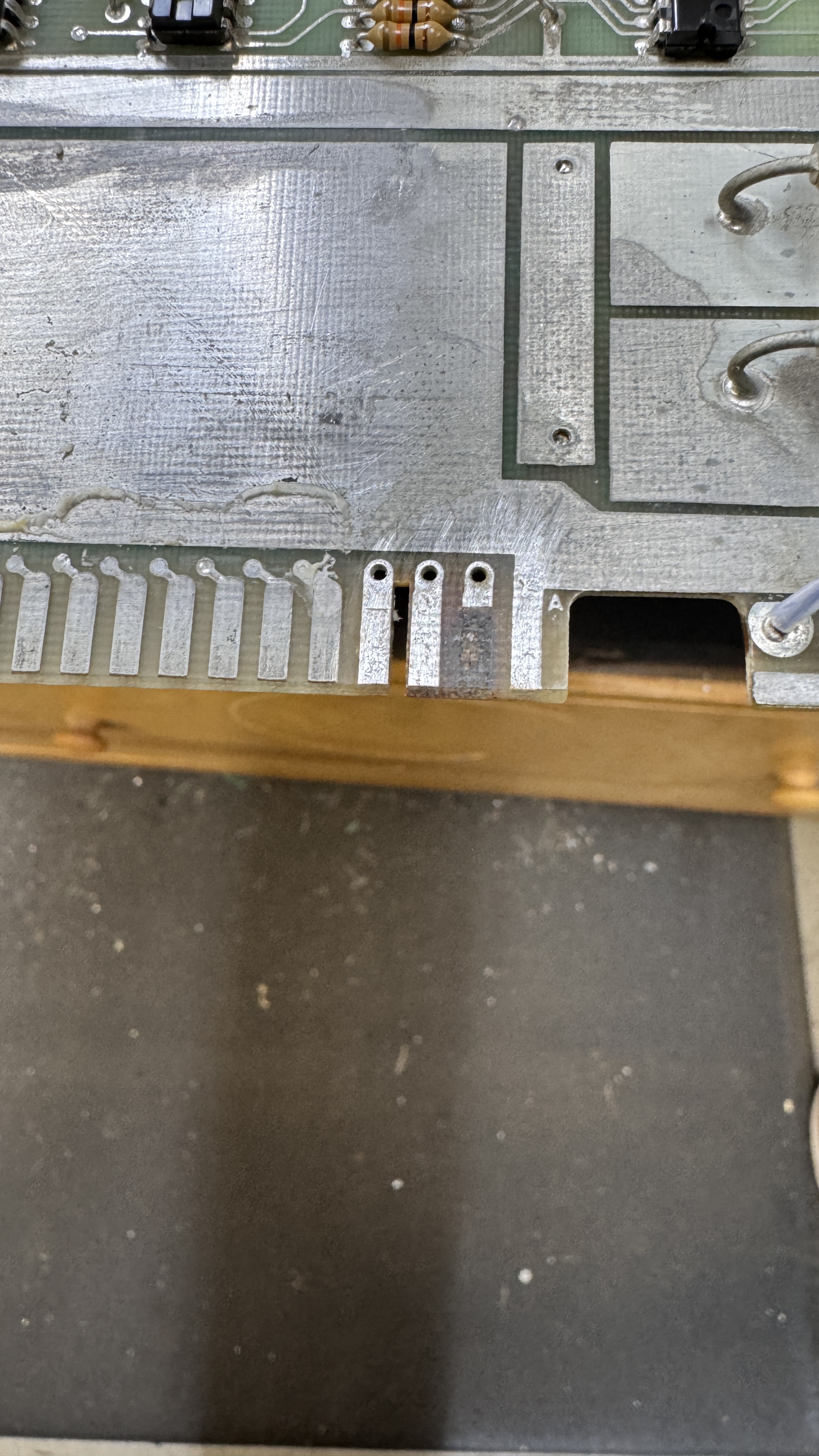

It required some edge repair too.. I have it trimmed and cleaned up here, added copper and then used Liquid Tin to recoat it.
At this point I was able to run RAM, ROM testing.. The 3 RAM that had been removed I replaced. It showed the RAM@K4 was bad.. Replacing it got the RAM check good and the game booted!
Testing showed that the black car was stuck in 4th gear. Replacing the 9312@F9 corrected that issue.
Board works!
