
I was asked if I’d take a look at some Xevious boards. Fortunately they had 2 sets. Having 2 sets of a non-working board is infinitely better than having 1 set when you have never worked on one. The chances of them both being dead identically are near zero. It allows some comparison so that you can get them both going..
My Atari Bench Power Test Rig has made creating adapters for each board I work on relatively easy. I can typically build one in a couple hours. Swapping between different game boards on the bench now takes all of a few seconds. It’s extremely useful when swapping between two or three of the same board to compare signals when something isn’t quite right.

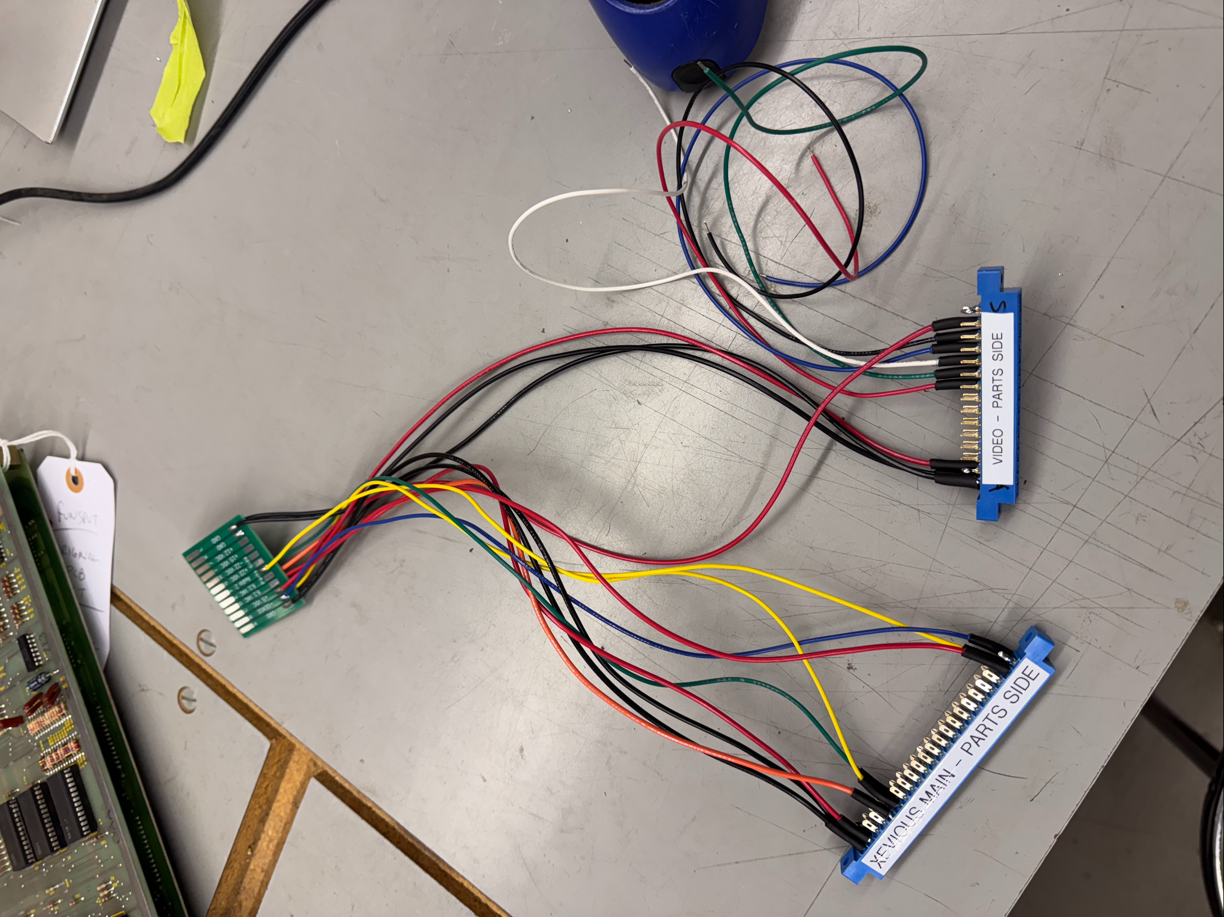

They all start the same way, I connect all of the power lines to the connectors and to my PCB. Next I connect all of the video lines to the edge connector and the appropriate Molex. Once I verify the power pins – I connect to the board set and verify video outputs and I generally get the repairs done up until the point of needing controls. Wiring in those comes last. In the end it becomes quite an efficient system for testing.. After the first board repair, it has paid for itself in time savings.
Board #1 – In for repair


Xevious comes as a two board set. CPU board has 3 x Z80s. The video board has a lot of ROMs and some video RAM. The CPU board is designed similar to DigDug where all three CPUs have their own ROM and they all share the same RAM. After building the harness and connecting it all up, the board was stone dead. Nothing going on at all. But at least clocks were working..
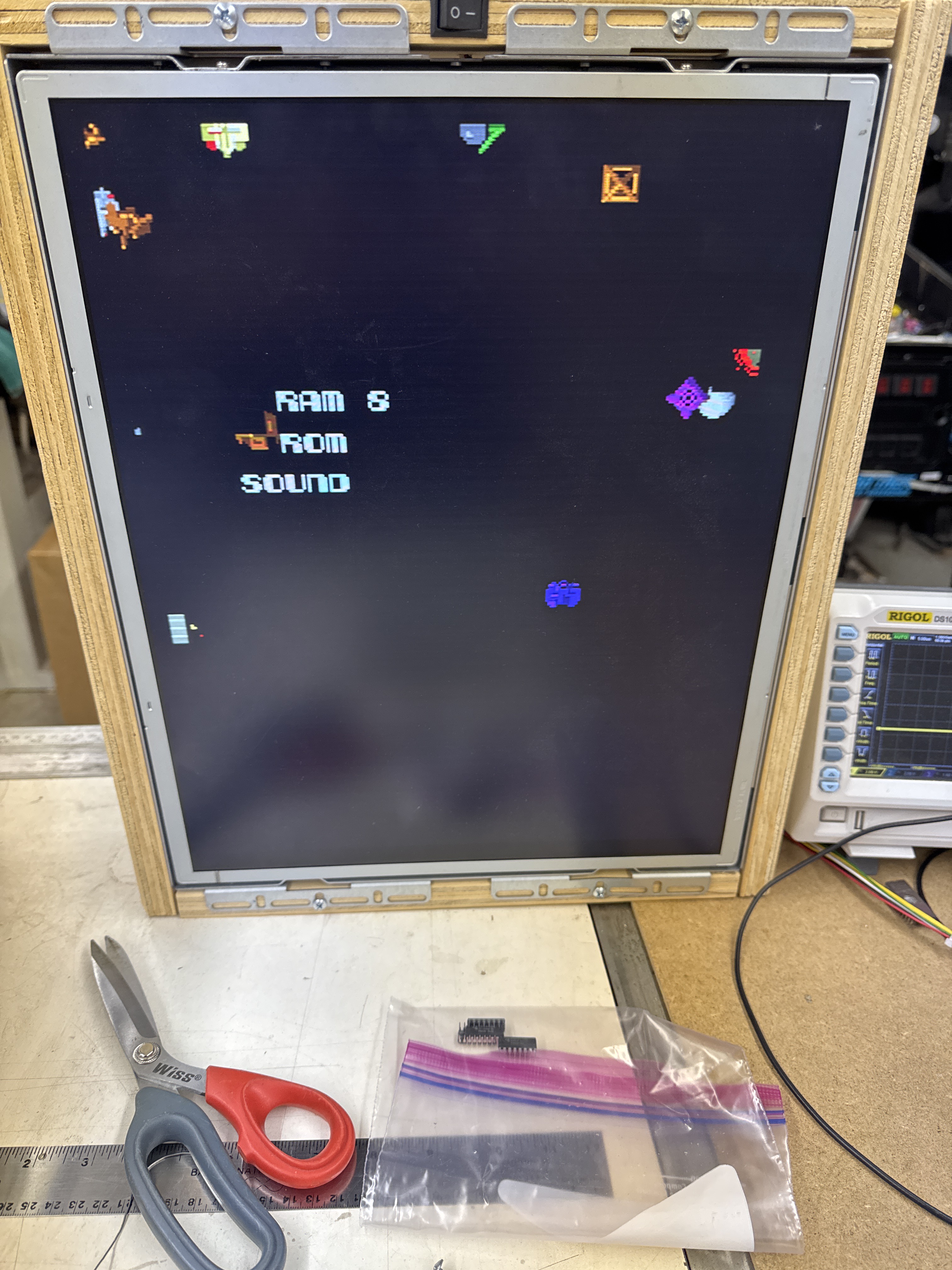
From here I removed all (42) of the socketed chips, cleaned and Deoxit’d the legs and reassembled. During this time I also created a FPGA Tester configuration for the Main CPU to test RAM and ROM. On the video board – I had to bench test all of the ROM. None are addressable via the CPUs and they should be checked so that there are no graphics glitches.
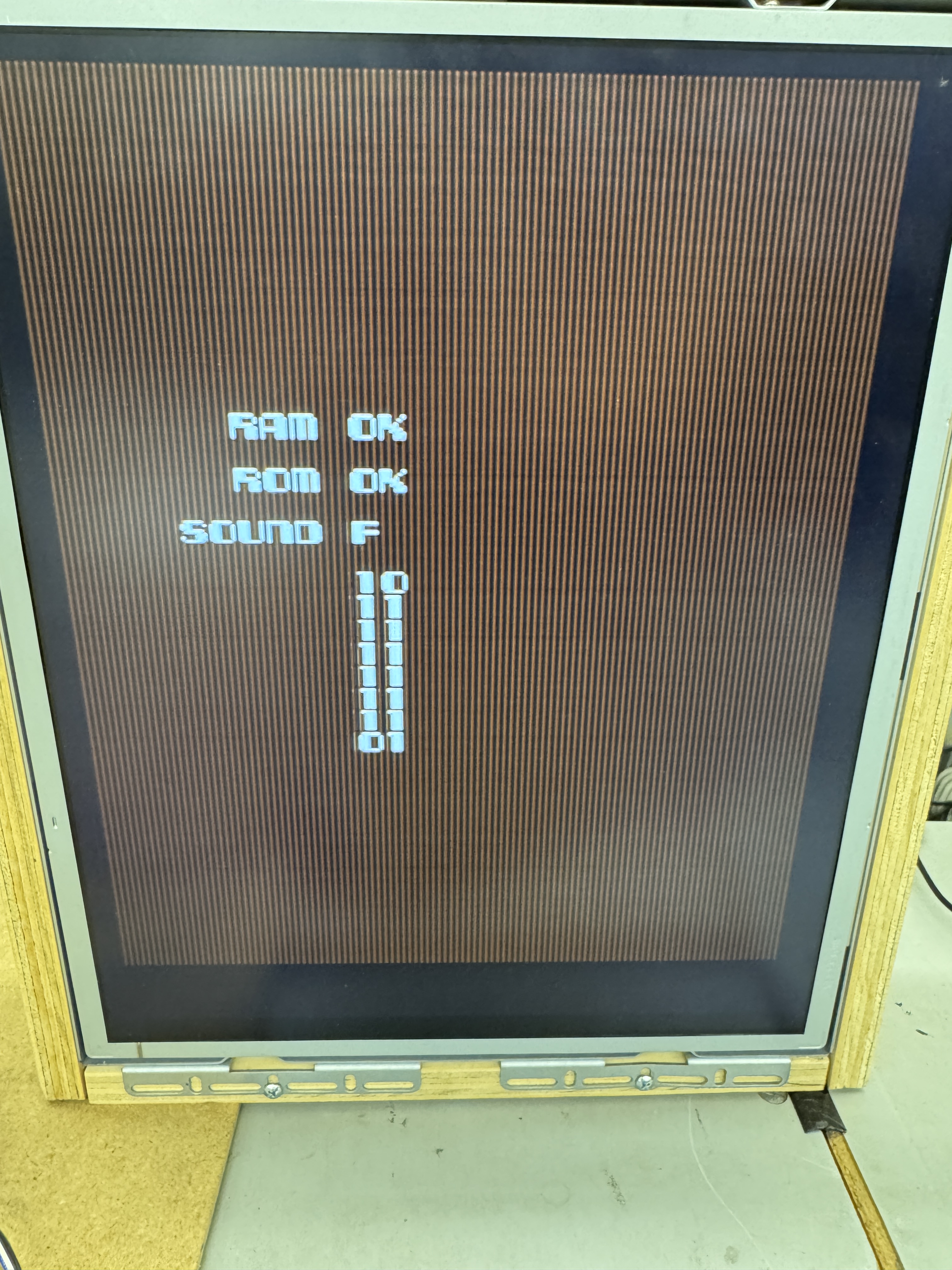
Once it was all back together, lots of things started working.. but the game didn’t boot. RAM test showed that bit#5 was not visible to the Main CPU. Reseating the 08xx custom@4L corrected this error.
Board booted!
First issue after boot was lines in the background. This a color RAM issue. Replaced 2149 RAM@5M. At this point the background was good but the sprites all had lines through them. Replacing 2149 RAM@6M fixed the sprites!
Board works!
Board #2 – In for repair
Did all of the same cleaning and pre-work to board #2. This one had a couple odd items.
First – someone put a PIA chip in one of the Z80 sockets. Board isn’t going to boot with a PIA. It also had a bad RAM@1H. After cleaning and replacing those parts, the board seemed to boot and run.. Leaving it on it would lock up randomly. Which can be really hard to find.. Sometimes it provided a RAM error (random chips) and sometimes it just locked up..
I connected the FPGA Tester and found that the Main CPU would have a some random memory errors over the course 500 cycles of testing.. The Motion CPU and Sound CPU had no RAM issues, good! It was Main CPU dependent.
At this point the sockets for the 08xx@4L and the CPU socket were not the cleanest, I replaced them just to eliminate them from the equation. Same intermittent RAM errors. I let the board run overnight to see if I could burn up the offending chip.. The issue did get slightly worse so that was good, but not stone dead as I had hoped.
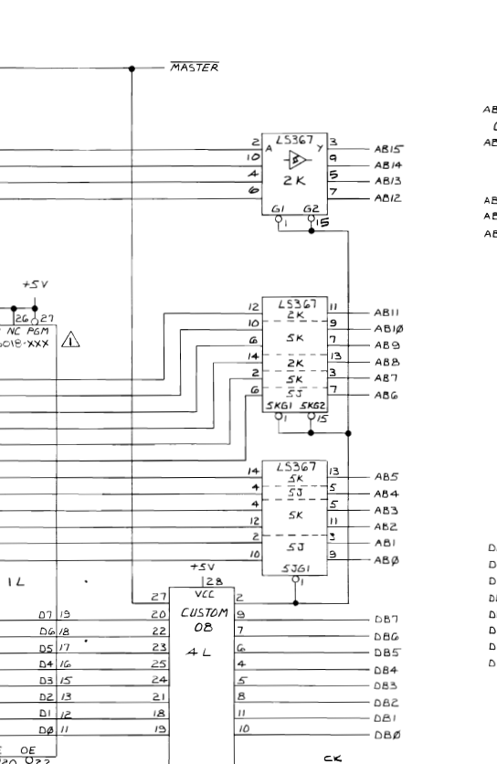
Something I had not really seen (or noticed) on other boards, the address bus lines were spread across different chips. I figured it was one of the LS367’s, but there were a number of them involved based on this design. Fortunately I had the tester running and the memory was not working correctly. Piggybacking a new chip on LS367@5K caused the errors to clear. Great! Replace the chip and ran over 4000 cycles to confirm it was the root cause.

Board works!
Board #3 – In for repair
Reported symptoms was there was no ‘RED’
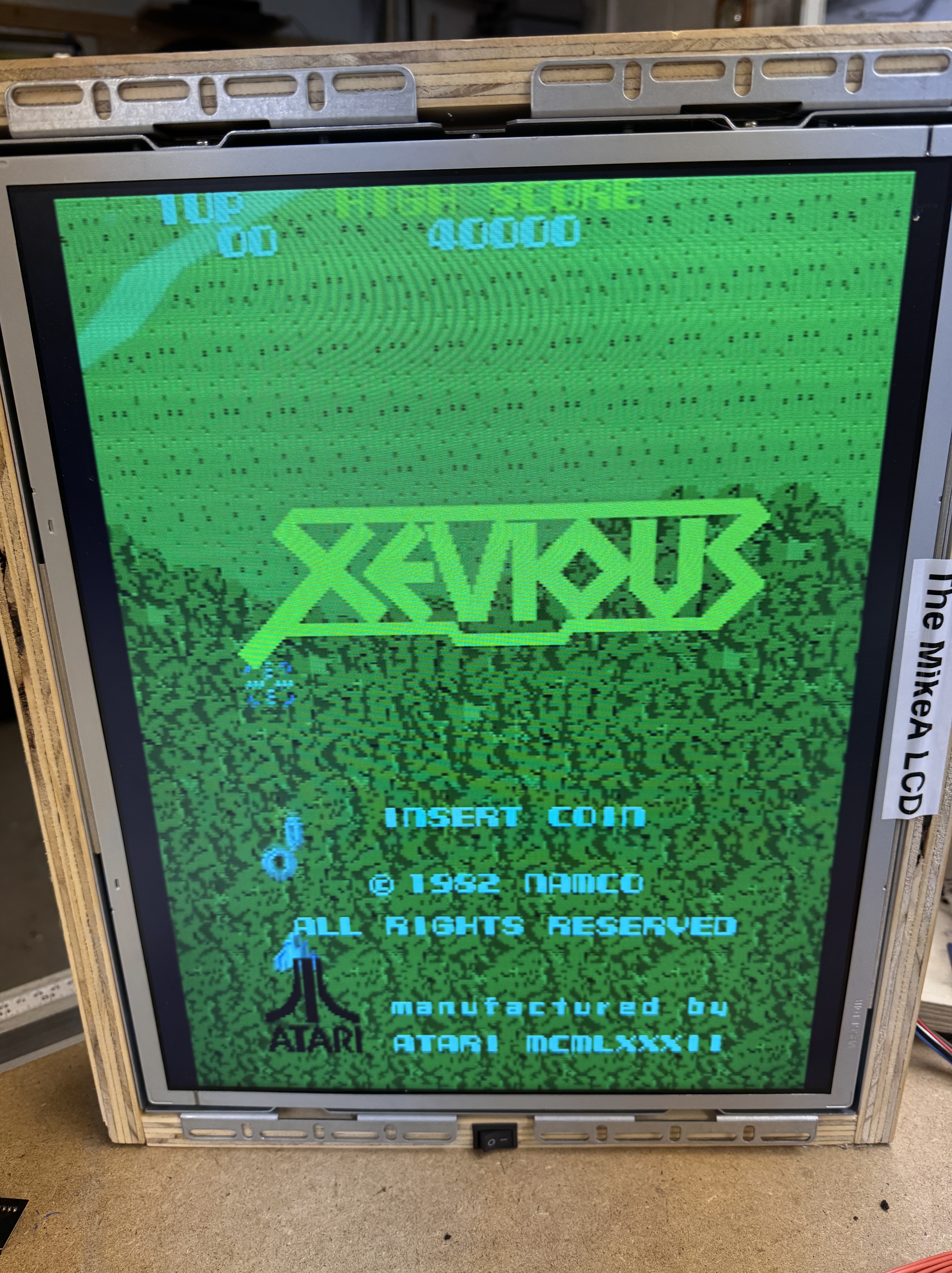
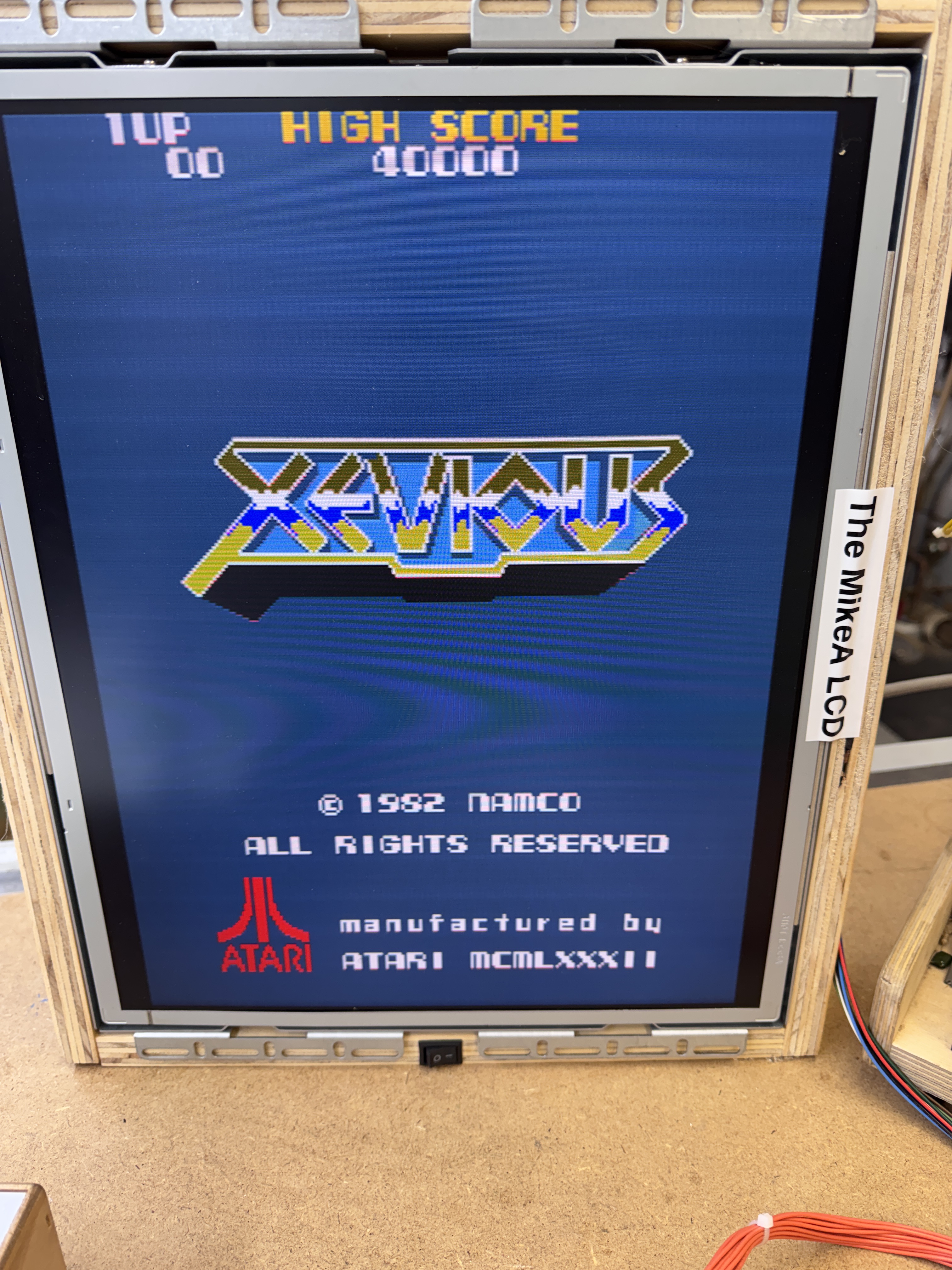
Agreed – no red. The other subtle symptom was that the background on the title screen was blue. It should have been black.
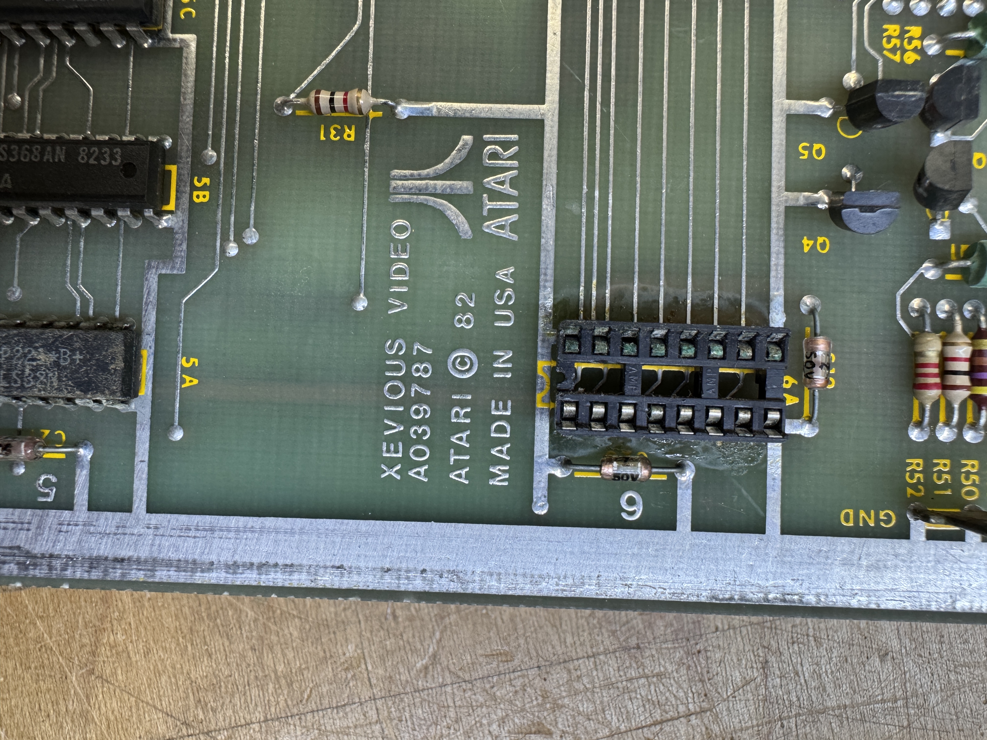
Here is the red color PROM@6A. It had been removed at some point in its life and the socket was green with corrosion. A little out of place on what was a very clean board. Replaced the socket and cleaned up the legs.. then got this..
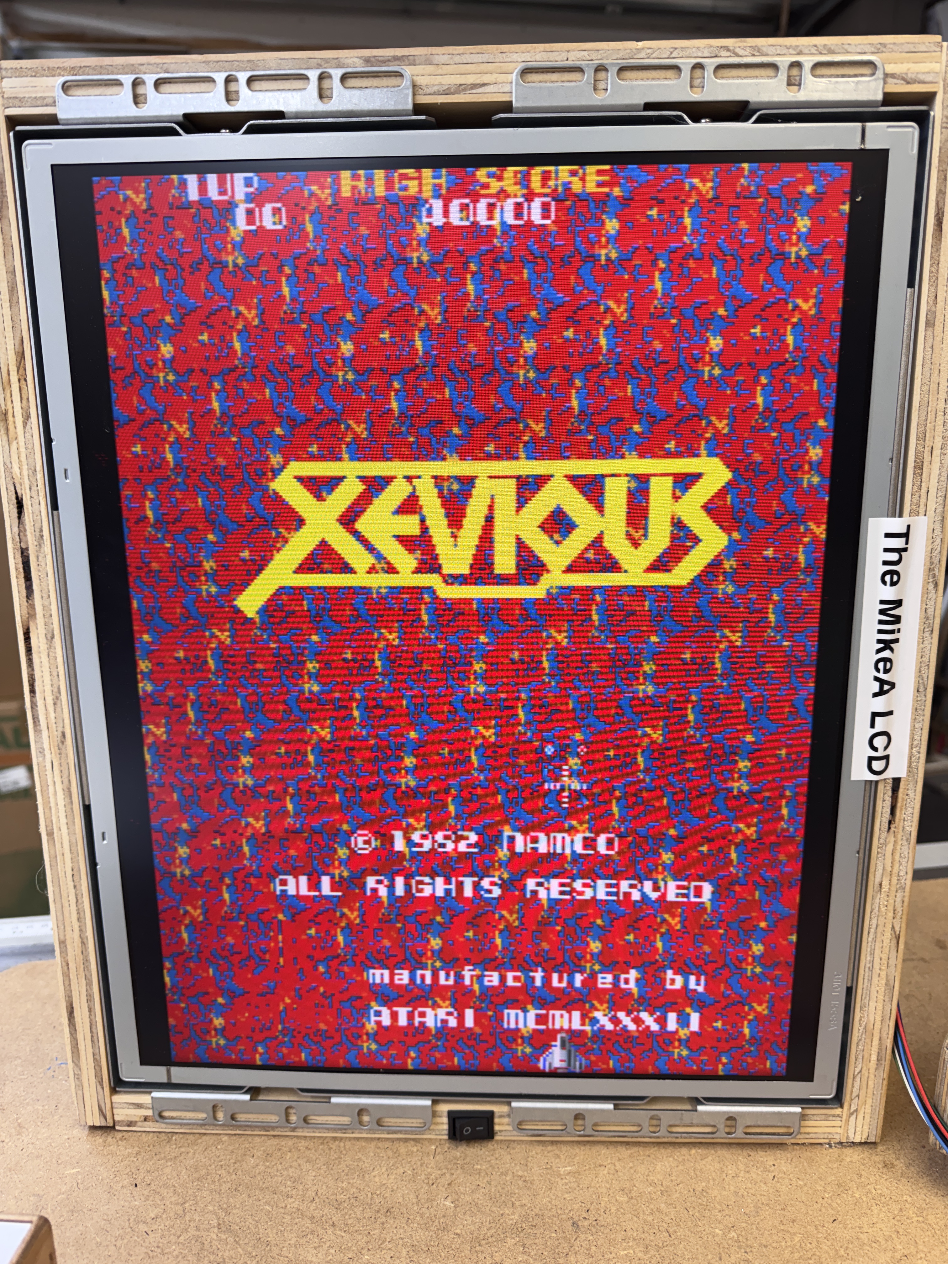
WAY TO MUCH RED! But only on the game screen. The title screen looked normal exactly as above with the blue background and a red Atari logo. After the distraction of verifying the color prom I just resocketed I looked elsewhere on the board.
Probing around the board led me to this area..
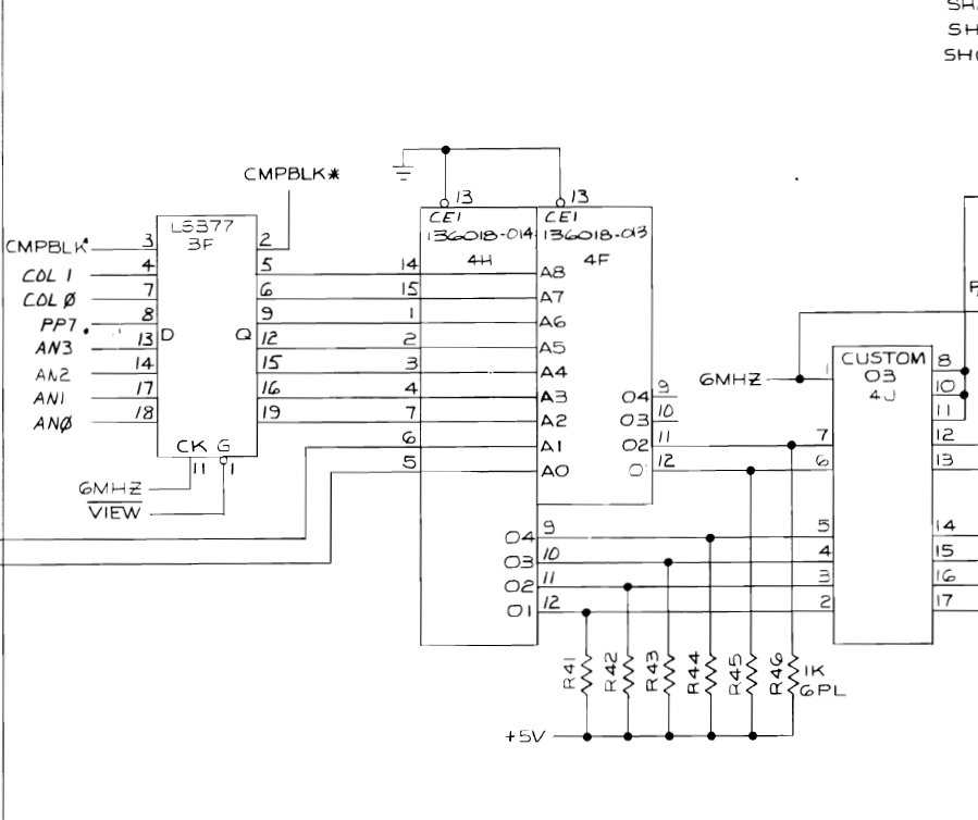
Here I determined that the color PROM@4F was controlling red for the background images.
I removed it and tested with a PROM adapter to be 100% sure before having a replacement burned.
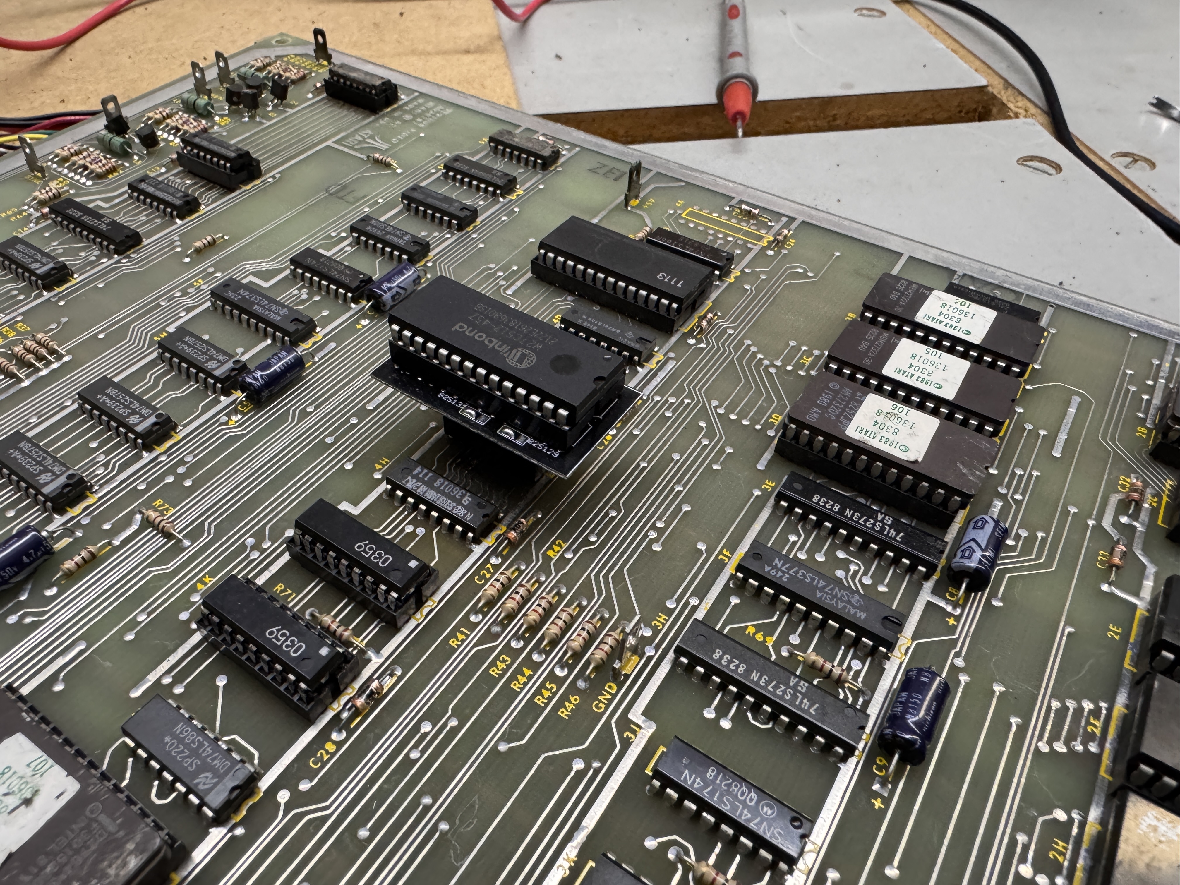
This corrected the color issue for the background – I got a new 82S131 burned. From here I did my standard board maintenance – removed chips – cleaned legs – etc..
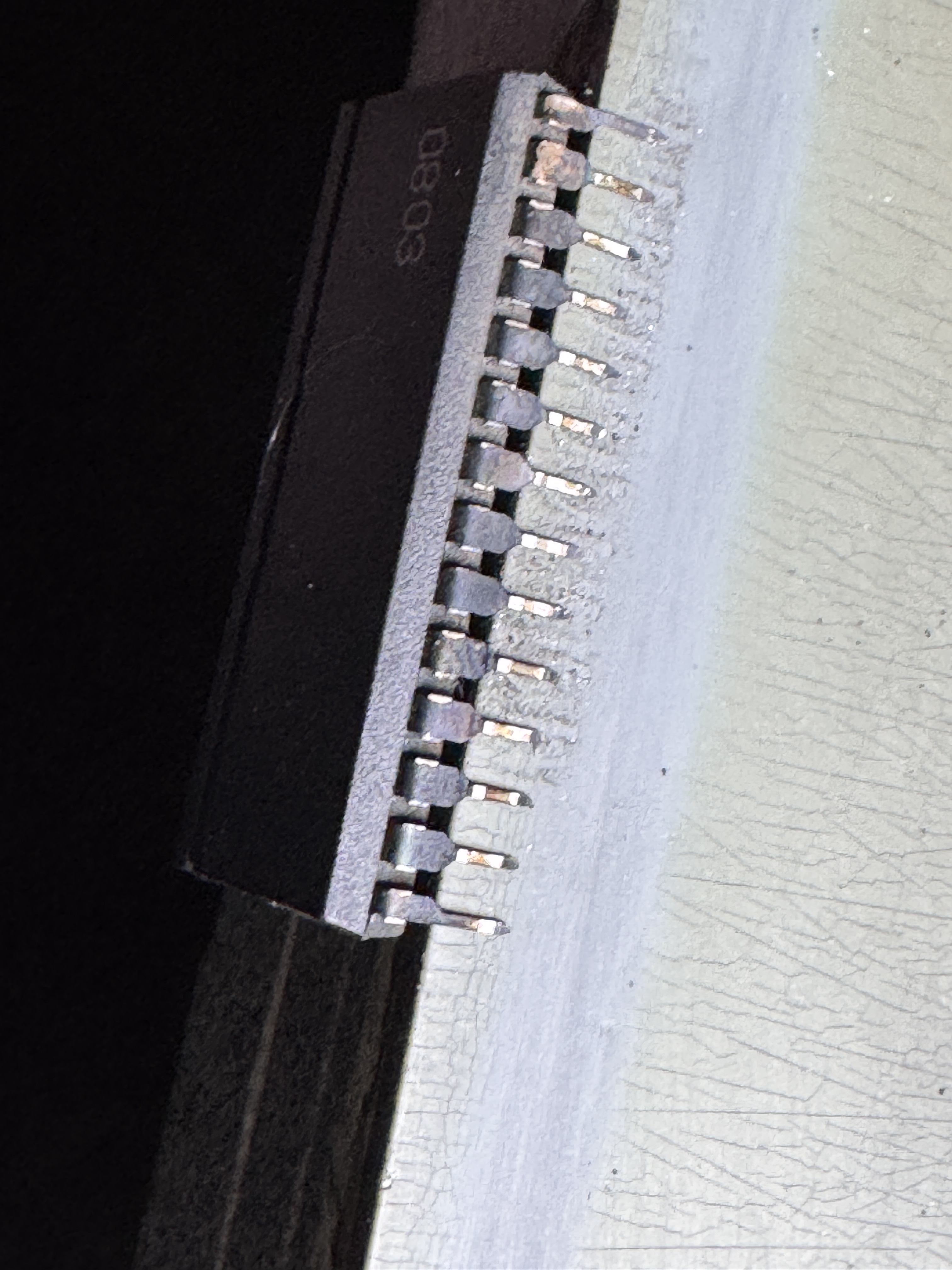
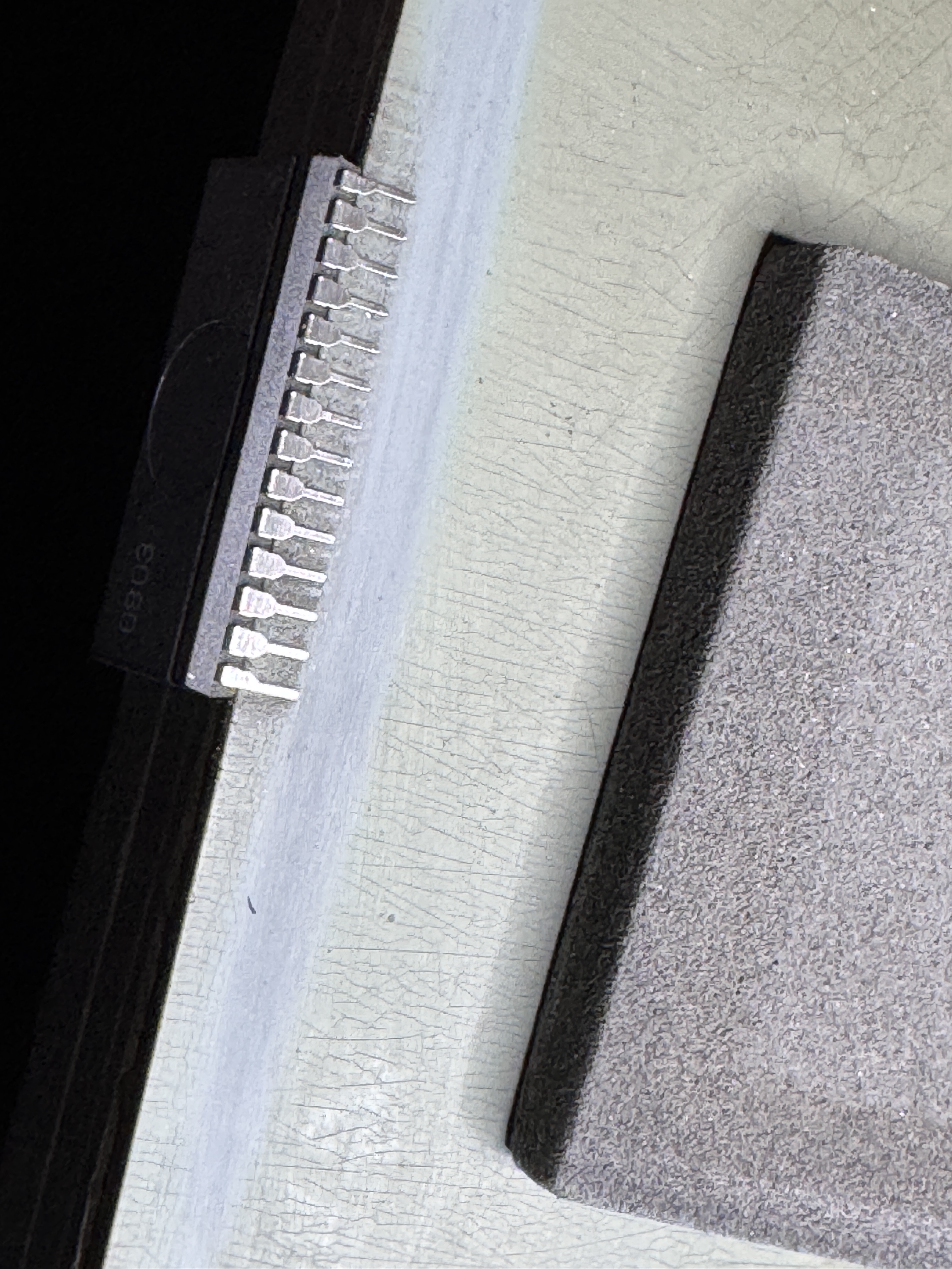
Here you can see the before and after. Most of the Namco customs have silver legs that tarnished. Removing the tarnish should hold another 40 years and make the game more reliable. I use Rust Erasers to polish them up..
Board works!
