I’ve always planned to do some Nintendo repairs and did a little on my own Donkey Kong board when the sound failed. I have a couple of them in my stash and even a couple of Punch Outs that I plan on working on.. Just never got to them..
That changed when one of my arcade customers asked me to fix a Popeye set.
I had started a bench adapter for Donkey Kong TKG4 – but had never completed it.. Luckily it can do a few different boards including Popeye.
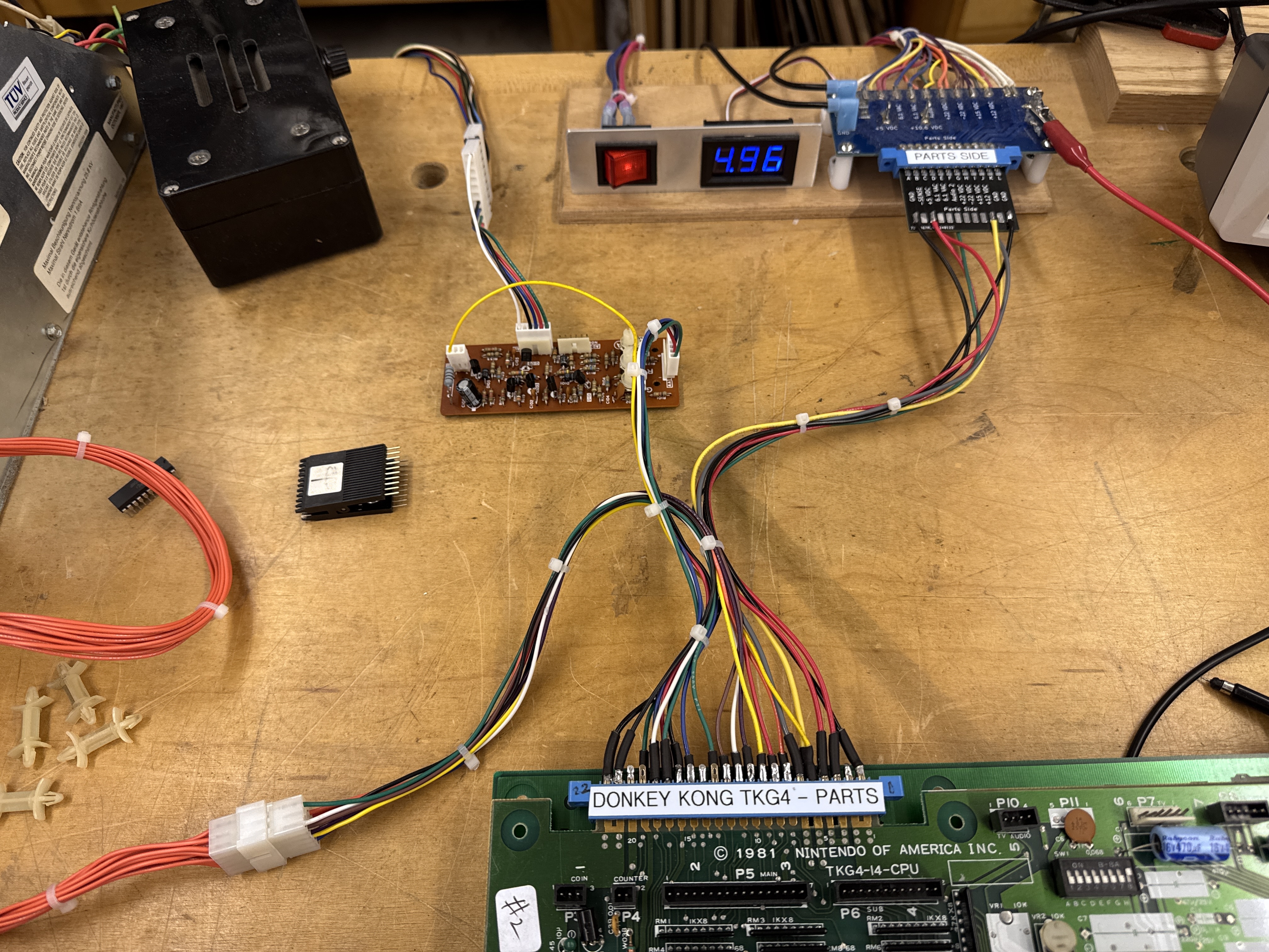
Here it is completed – it’s relatively simple. I needed to use the Nintendo color inverter board to get the video to display. Even then Popeye will not sync to my LCDs for some reason (which are just simpler to work with on the bench). I also have a dead Sanyo EZ for the bench to get going.. also on the list.
Board #1 – Popeye – Board in for repair
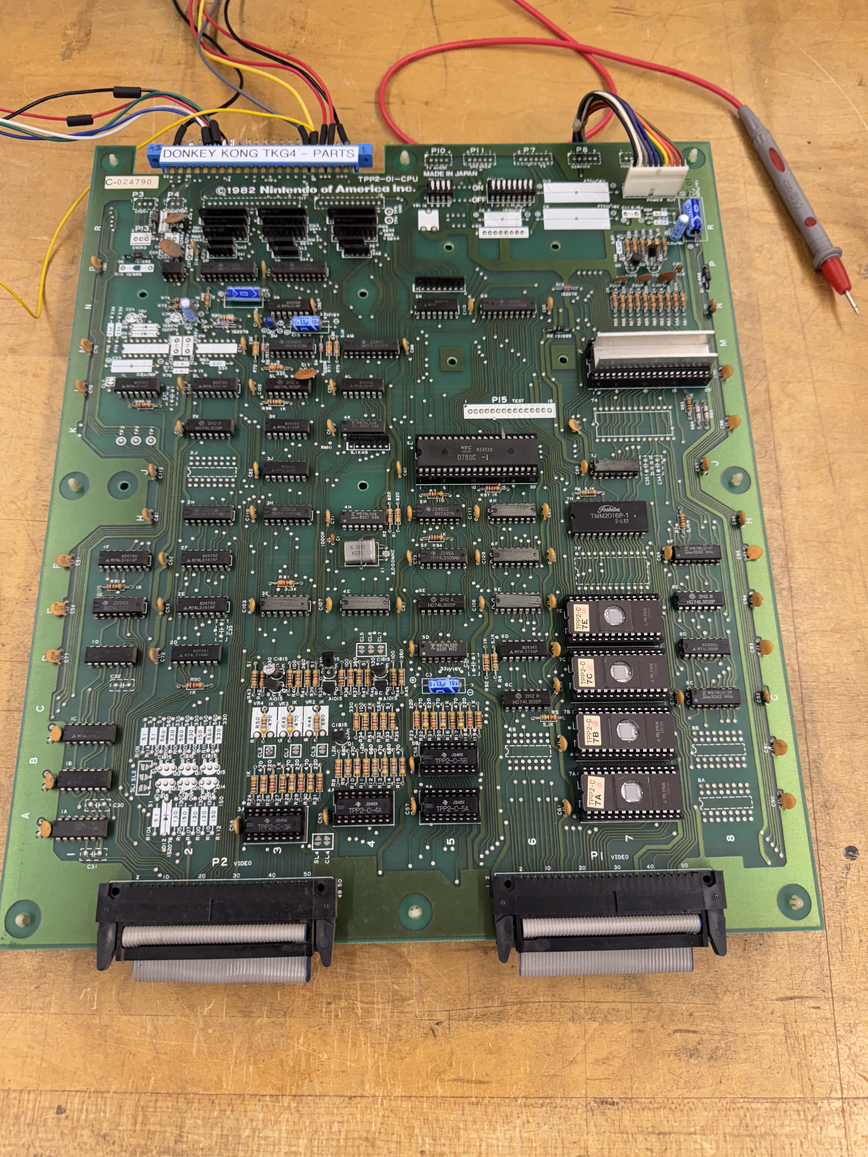
Here is where I started – Power and video connections and a lot of probing around trying to figure out what was happening. The boards powered up to garbage. Starting at the CPU the /RESET line was pinned low.. Something was obviously messed up in the reset circuit. Pulled the CPU and it would not watchdog. I pulled the 4 program ROMs, 1 was bad (7A).


To me, the reset circuit seems to be needlessly complicated. At first it seemed like the LS161@2L could be the issue – except Pin1 and 9 were being pulled low. I removed it to divide and conquer the problem. The LS161 was good and the /PONRES (Power on reset) was low. Spent some time on the /PONRES circuit and the only thing that made sense was the 74123 was bad. Removed it and my tester said it was good. This is where having another Popeye board would have been helpful. Even if it didn’t work – they all die differently. I checked my dead Donkey Kong board and this circuit seemed to be different but it had a 74123 – so I borrowed it (never ran into the chip before). It did fix this circuit however. It now holds the /PONRES line low for just half a second or so before going high. Sometimes the testers say chips are good when they are not.
During this ‘discovery phase’ I worked on an FPGA Tester config and set up ROM and RAM tests. The memory map shows lots of RAM segments, but the only testable range was x8C00-x8FFF. I got that to test good (for a while).. The ROMs were jumping all over the place.. Even pulling them returned odd checksums vs. stable ’empty socket’ checksums. Determined the PLA(74LS367@6H) was bad. Replacing it stabilized the checksums – but they kept coming back different than the actual ROMs. (I believe this is from a copy protection scheme where they flip bits to prevent pirating, etc.) While getting the ROMs to read correctly, the RAM@7H stopped reading. Checking the chip – /MEMWR was not functioning. Tracing backwards – the LS04@4K had died – it was a Fujitsu.. Replaced it and the RAM was testing good again.
Now that the RAM and ROM were readable from the CPU socket – I wanted to see if I could get the board to do anything. Above I pulled up Pin1 and 9 on the LS161@2L and pulled the reset pin (26) on the Z80 – I got it to boot and do just a little bit.. Notice the players on the bottom.. Finally something was working a little bit.

I went back and refocused on the /PONRES – the 74123 got swapped and that circuit at least started working as expected.. Working all through the watchdog reset side of the circuit.. I could not get the board watchdog reset on its own. Somewhere along the way I had the idea to pull the Z80 BUSRQ pin26 vs the RESET pin25 and pulled it high..
It let the game boot much further that my prior trick… and also gave me a clue.

BUSRQ was connected into a section of the circuit I had not probed around in up until this point.. I spent time looking at all the chips until I found LS04@1A was not working.. Replacing it got me to a bootable (without bypasses/pullups) PCB stack.

There is more to do.. I got it to boot clean below.. but it resets randomly..

Colors are off because of inverter board adjustments.. I need to get my Sanyo running.. However.. this didn’t last very long..
Up until this point the board had multiple chip failures.. This failure started as twitching and progressively got worse. I spent some time looking for it but the symptoms kept changing.. Twitching, resetting, RAM errors, ROM errors, etc. Finally I let it run overnight until it was completely jammed up and would not boot at all.
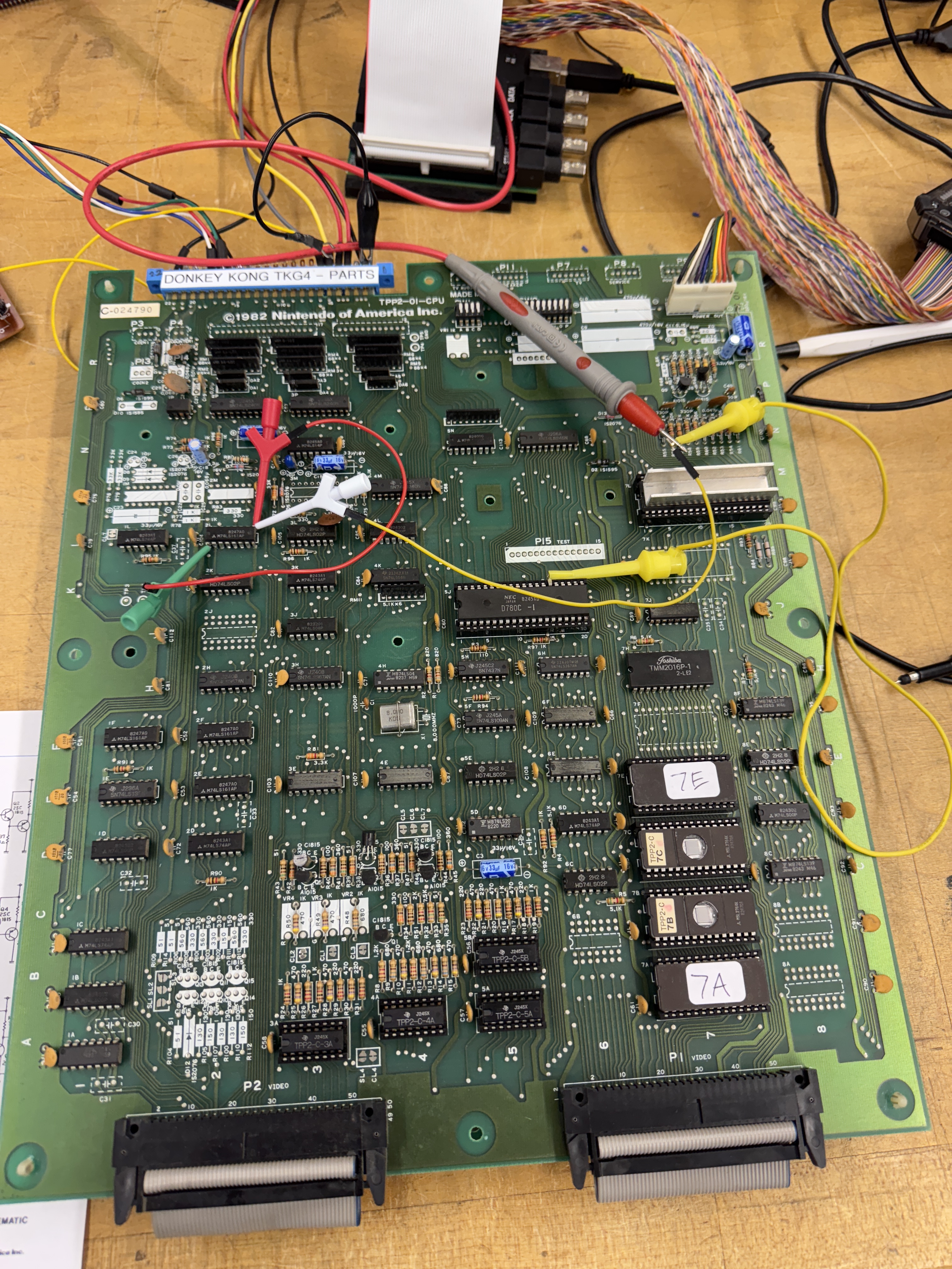
Here I reconnected to the FPGA Catbox and ran RAM and ROM tests.. Both failed.. Interesting. I immediately went to the PLA@6F.

It is a 74LS367 and I had already replaced the one @6H. This corrected the booting and stability issue. So yes.. I watched that chip die over the course of a couple of days. During this – the character ROM on the video board failed – ROM 5N

Look real close and the numbers have extra pixels. Doing a compare of the ROM to MAME, one of the bits failed across half of the ROM.
Last issue is that after resting for a couple of days – first power up has jumbled graphics that self correct inside of a minute. Seems like a RAM issue – but finding it has been problematic. Freeze spray has not helped. I’m running the board though various power cycles to see if I can get the chip to complete failing.

The background graphics are messed up.. but self correct.
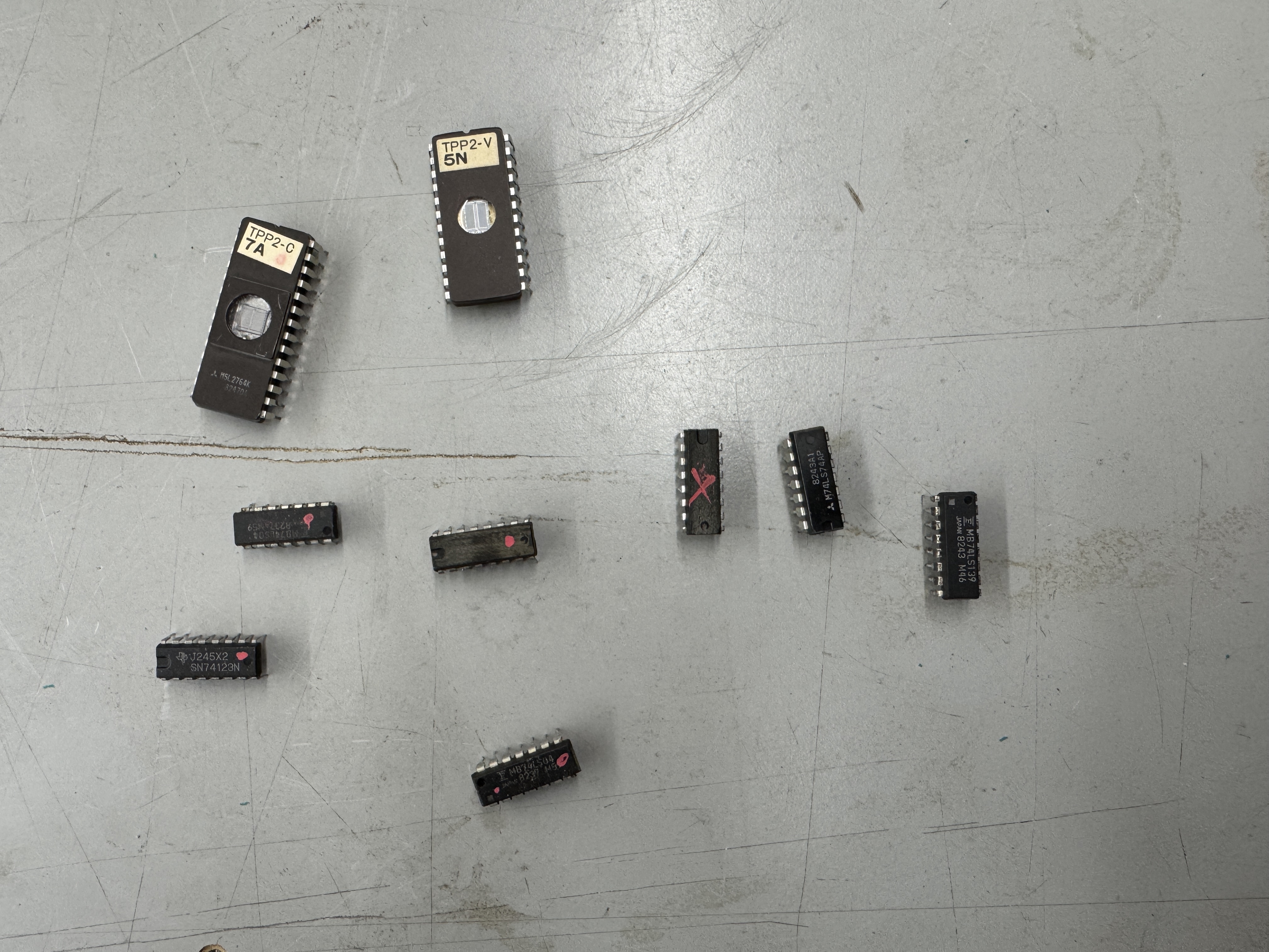
The debris so far..
The last issue took a long time to track down.
Same video from above..
The first time around this game started this but locked up due to the 74LS367@6F. This issue was seemingly unrelated.. It seemed like a RAM issue and the RAM in this area was controlling the background (as far as I could tell by probing)

But all of them seemed like they were working correctly – I checked supporting chips, etc. The issue would change too – sometime the jitters would just stop – sometimes they seemed to be unstoppable. I decided to work backwards to the CPU board and check the chips feeding these RAM. All seemed good. The only RAM left was the CPU RAM I had replaced initially because of the failed RAM@7H. Usually CPU RAM when it fails causes crashing vs. background image instability.. But I don’t know Nintendo and how they used the RAM. I swapped out the RAM with the fastest one I have and it seems to have corrected the instability issues. I’ll test more .. however..

During some burn in testing.. Some of the sprites decided to scramble.. Going backwards.. However I was able to locate a bad RAM@U1 on the video board. That corrected the sprites and also fixed the jitters. Borderline RAM that FINALLY died!
Board works!
Board #2 – Donkey Kong Jr. – Board in for repair
This one came in with reported missing sprites… I did board maintenance, chip cleaning and inspection..


First – the EPROM@3H was backwards (and ruined).. It is the sound ROM.. Burned a new one. While cleaning chip legs – I found a number of ROMs with legs that had been bent under.. It’s possible they were touching… But not sure. All of this got corrected up front. I downloaded and verified all ROMs since DK does not have self test.
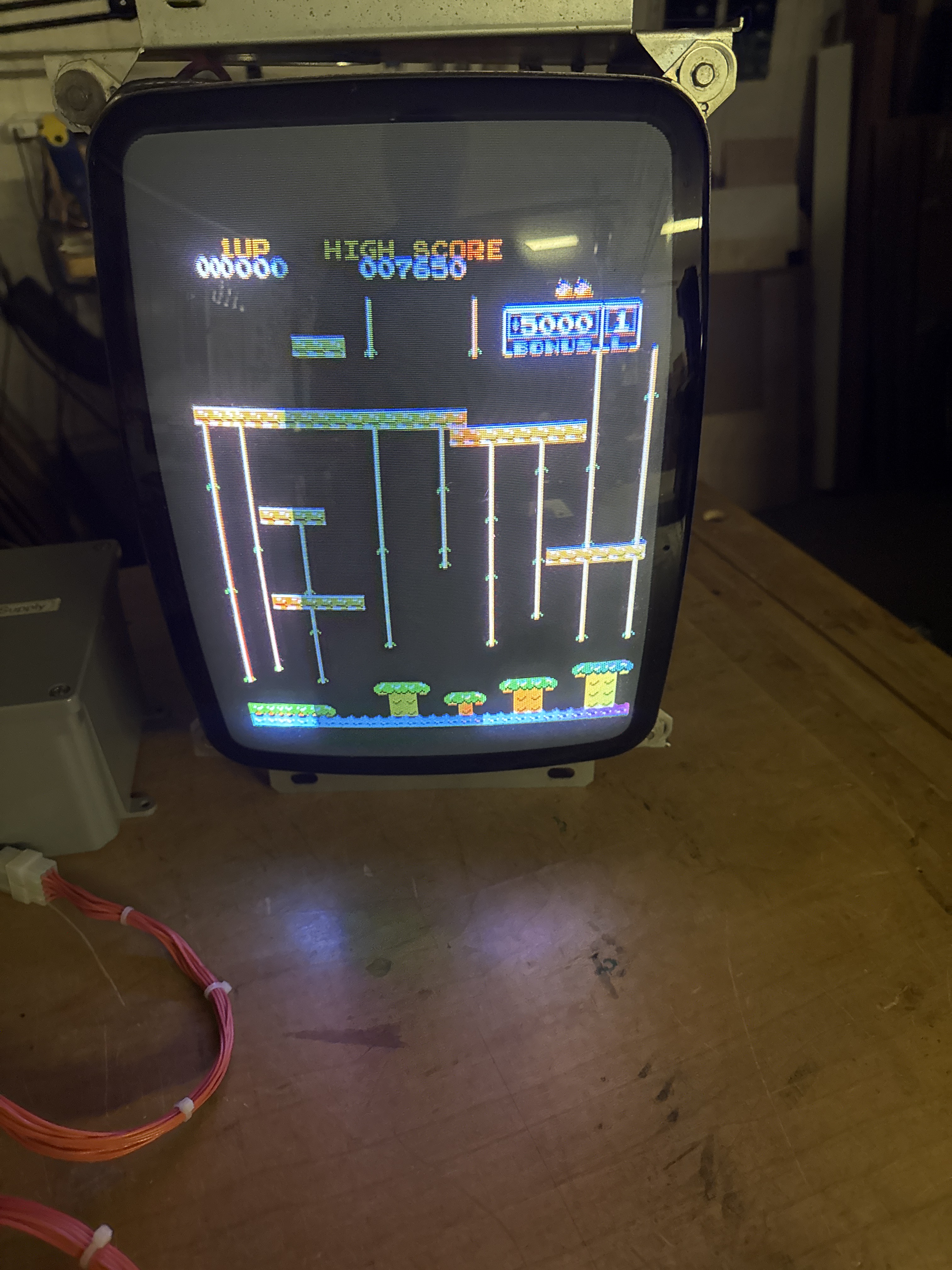
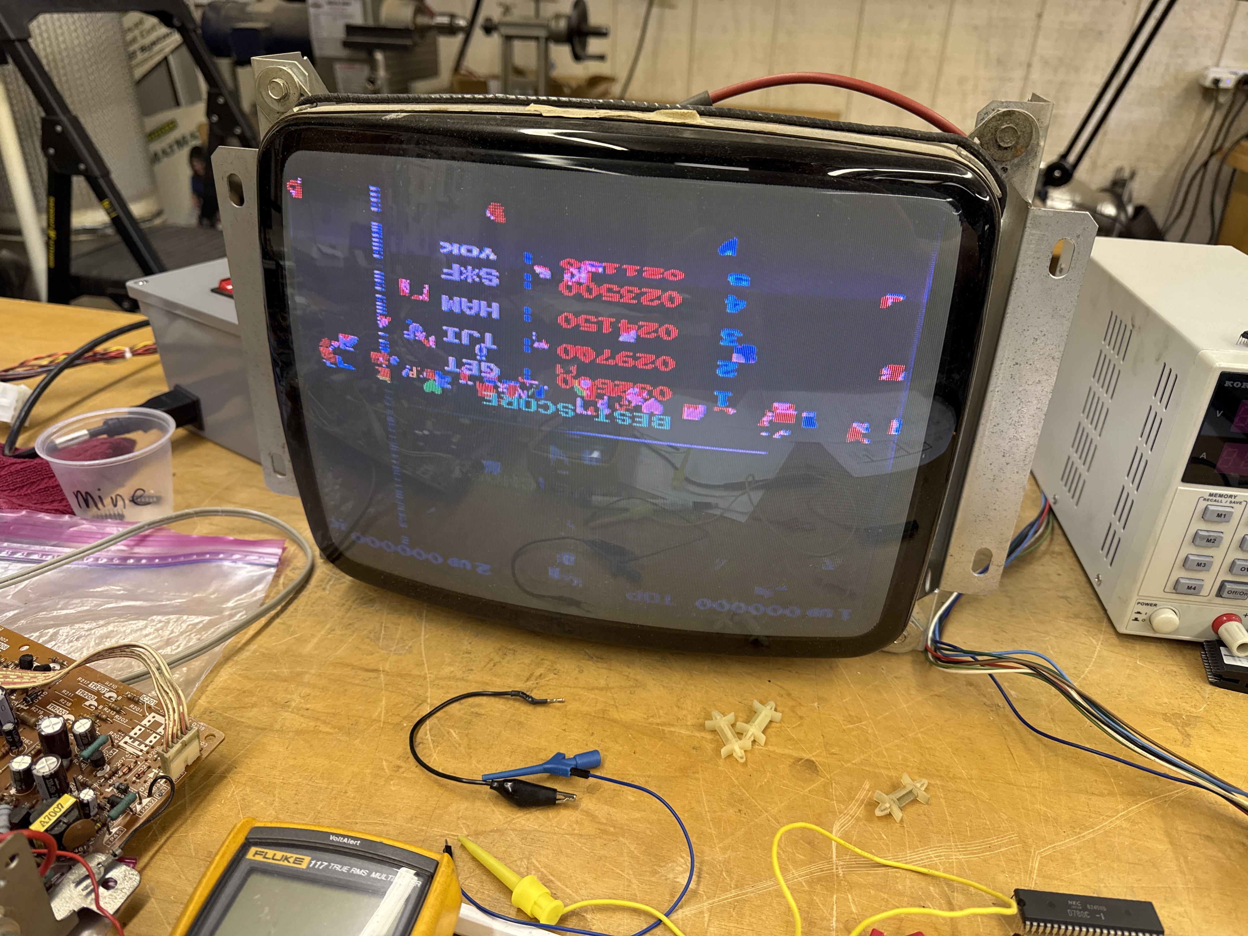
After power up – no sprites.. I could operate the controls and hear the sounds – just nothing visible. The first issue I had to fix was this..
It actually starts much worse than this and gradually clears up 100% perfect over the course of about 1 minute or so.. The first 20+ seconds the monitor will not sync at all…
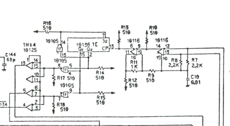
The 10136@1E is a chip that has a large heatsink on it.. It is the cause of this issue and they are not easy to obtain.. It’s a bit pricey to replace.. I had an extra from when I fixed my own board with the same problem.
Finding the missing sprites took a little time.. Comparing to my DK board – the sprite ROMs were not active. After some probing of the circuits..

This part of the video board is central to sprites getting displayed. Grounding LS20@7N pin 6 caused sprite garbage to appear.. perfect.. I was on the trail. I backed up a bit and determined there was no clock going into the LS161’s @5L and @5K. Probing all of the inputs to the LS20 – pin 2 was high – causing the output to be high.. It was being fed from LS74@4L.
I piggybacked a LS74 and it made no difference.. . However I lifted Pin9’s leg and then probed it with the scope and it had signal. Here I prove that piggybacking to see if a chip is bad doesn’t always work – but using it as a poor mans logic comparator does work many times!
Replacing LS74@4L..
Board works!
Board #3 – 8 Ball Action – De-convert back to a Donkey Kong
This one should have been simple, right? I didn’t power the board up with 8 Ball Action but it had been running..
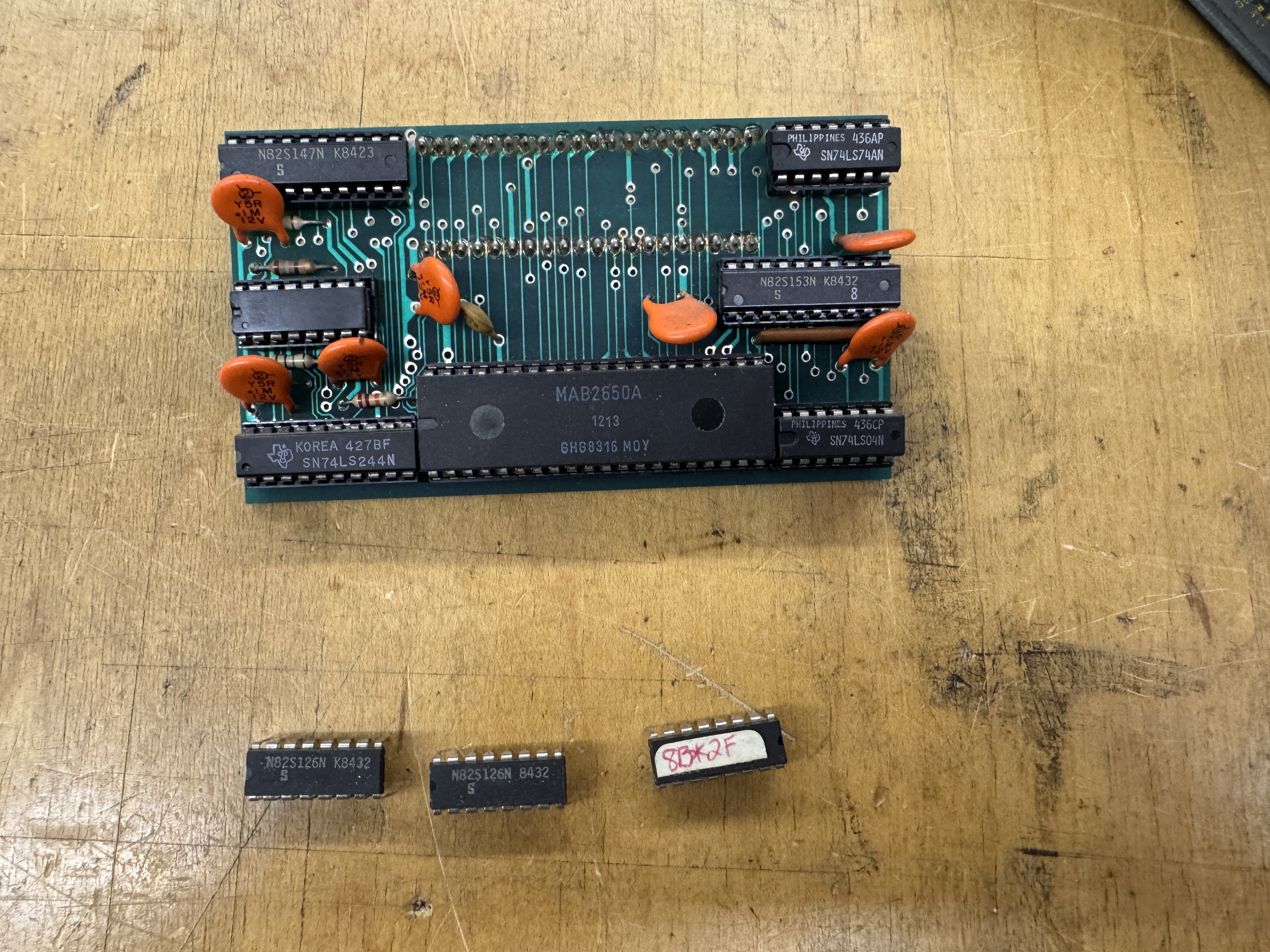
All of the EPROMs needed to be removed and reprogrammed and this is the kit that converts Donkey Kong to 8 Ball Action. 3 PROMs and a daughter board. The CPU is not a Z80.. It’s a Signetics 2650 . Anyone want a kit?
On the bench..
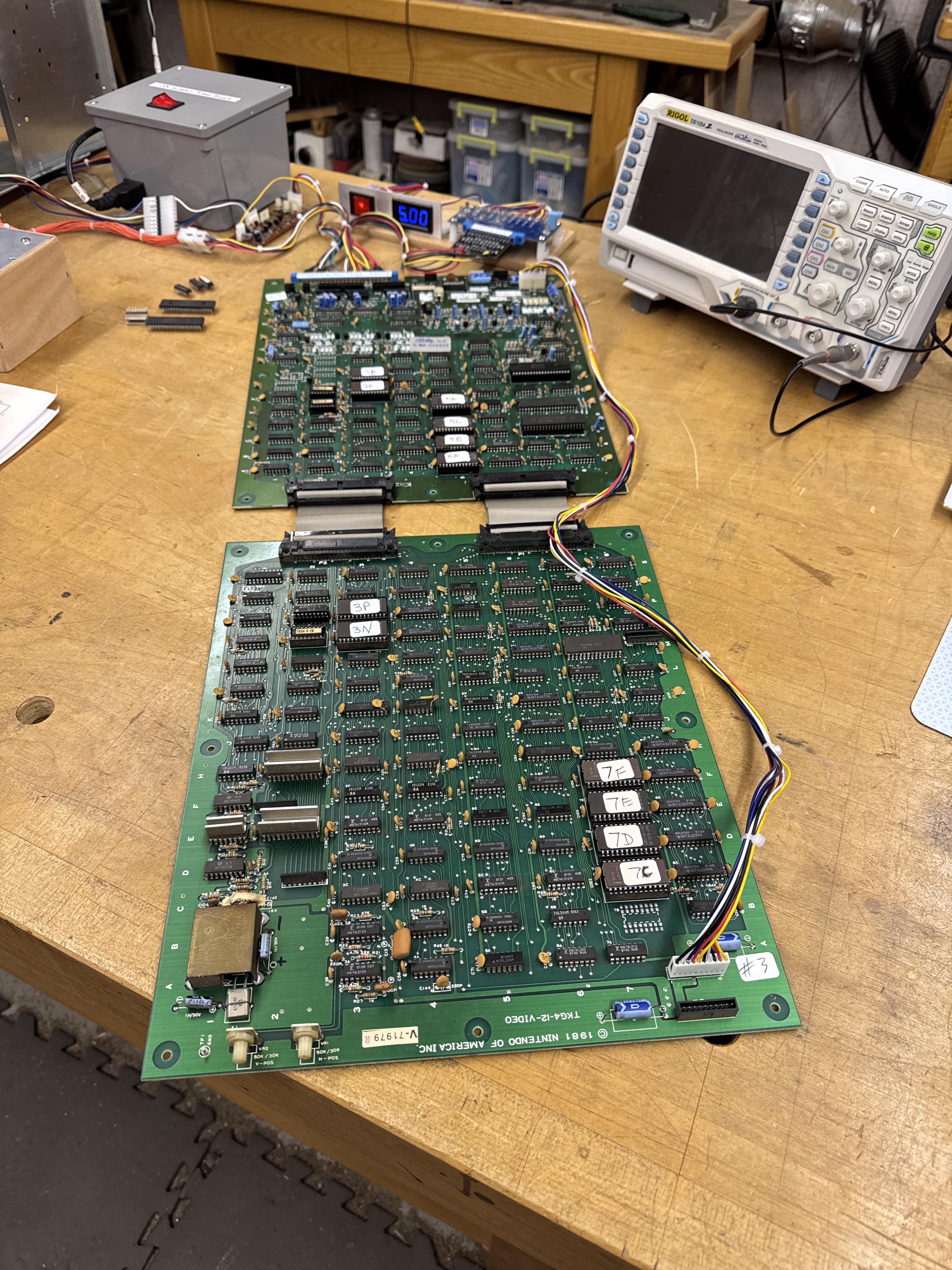
I did all of the normal chip cleaning, etc. The 8035@7H crumbled, 4+ legs flaked off.. So it got replaced. I forget to get pics, but some the text was scrambled depending on the screen.
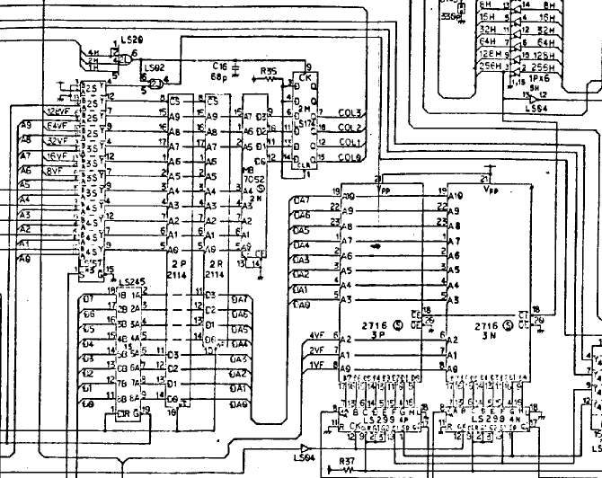
Probing around showed that the LS245@1S was bad. Replacing it corrected the scrambled text. Running the board over night brought the next issue.. A screen with lots of ‘00000’s mixed in.. RAM@2P had failed. Replacing it corrected the graphics… again..
Last issue was intermittent sprite sparkles and blocky graphics. Narrowed to the ROM socket@7F. I ran this board extra hours – it had sat on a shelf for a significant period of time and I expected more failures.. but it held up nicely after the last fix.
Board works!
Board #4 – Board in for repair
This one got shipped directly from eBay by its new owner.. Known not working as described in the listing – accurate.
3 of the 4 Nintendo boards recently have had this same video issue.. Note: This video is not from this board.. just an example.
It is caused by the 10136@1E on the video board. Replacing that got the video board running 100%. I tested it with a known good CPU board.
The CPU board from this set put up a battle…
Testing showed..

Data line D2 was being dragged down to ground. Clearly visible on the scope. Unfortunately D2 is directly attached to a LOT of chips.. There were at least 16 places it was directly connected.
Checks and tricks I used before having to go brute force..
- Removed the socketed ROMs @5A, 5B, 5C, 5E – no difference
- Removed socketed chip 8035@7H – no difference
- Swapped in a known good video board to eliminate ‘the other side’ – no difference
- Checked resistance of D2 vs. the other data lines. ~12K – so not shorted and similar to the others….
- Ran for a couple hours and looked for a warm chip. None..
- While running a memory test – set the scope to trigger if the voltage pulled up above the top of the pattern (~2v) and piggybacked all of the chips on the databus.. nothing conclusive.
No tricking this one.. Brute force it is. At this point I could have started snipping D2 legs – but I’m not a fan of that honestly..
- Removed 54LS245@6A – this connects the CPU board to the Video board – It is ceramic so I figure it gets hot – no difference
- Removed 8257 Direct Memory Access Controller – no difference
- Removed RAM@3C – no difference
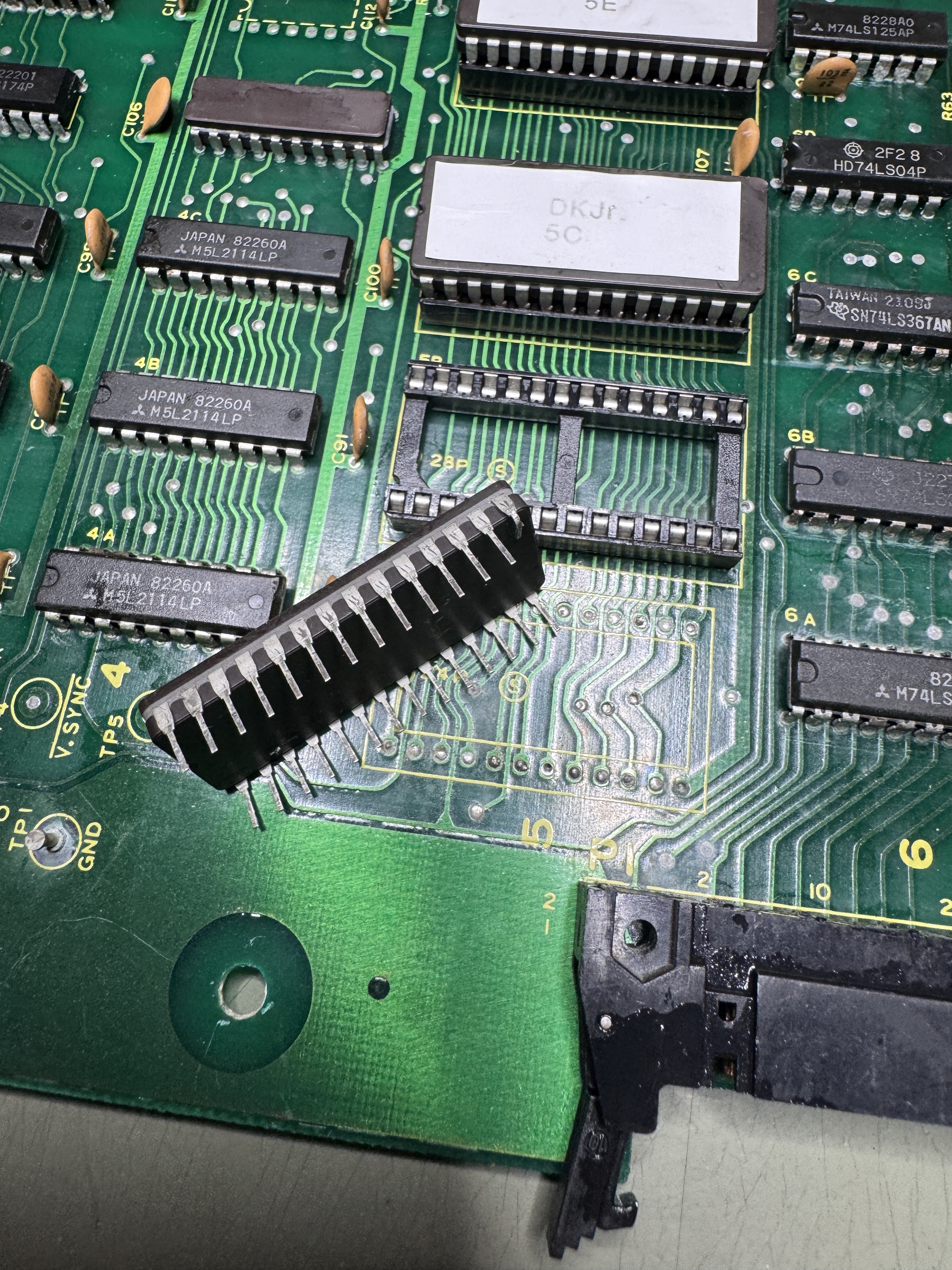
- Started to remove LS175@3D and noticed this!

I’d looked at the back for shorts – this is actually very tiny and not visible from ‘the other side’ of the pin. It was on D2 AND the connection didn’t beep out to the adjacent RAM – could I be that lucky? No.. I reflowed it, checked continuity.. retested.. D2 still being dragged down. Removed it.
The board has a lot of open holes at the moment..
Removed LS373@2N – the signals looked a little odd at this one, however – no difference
At this point I had 6 more chips to remove… Then my desolder gun decided to be problematic and I managed to crack the plastic connector at the neck.. yay… I dragged out my old cheapy desolder station and got it going.. However I wasn’t going to keep desoldering chips..
Time for a bigger hammer .. I decided to start clipping legs..

All of these LS240s are on the databus. I beeped out the connections because they are difficult to read here (and seem to be labeled wrong) D2 is on Pin16.. Cut Pin16@2P – PROBLEM SOLVED! D2 back to normal.. cleaned up all work – soldered all the removed chips back the board booted! Nice.
At this point I was finally able to test ROMs – the ROM@5B tested bad.. I downloaded and compared.

A single bit had flipped – I erased and reburned the EPROM.
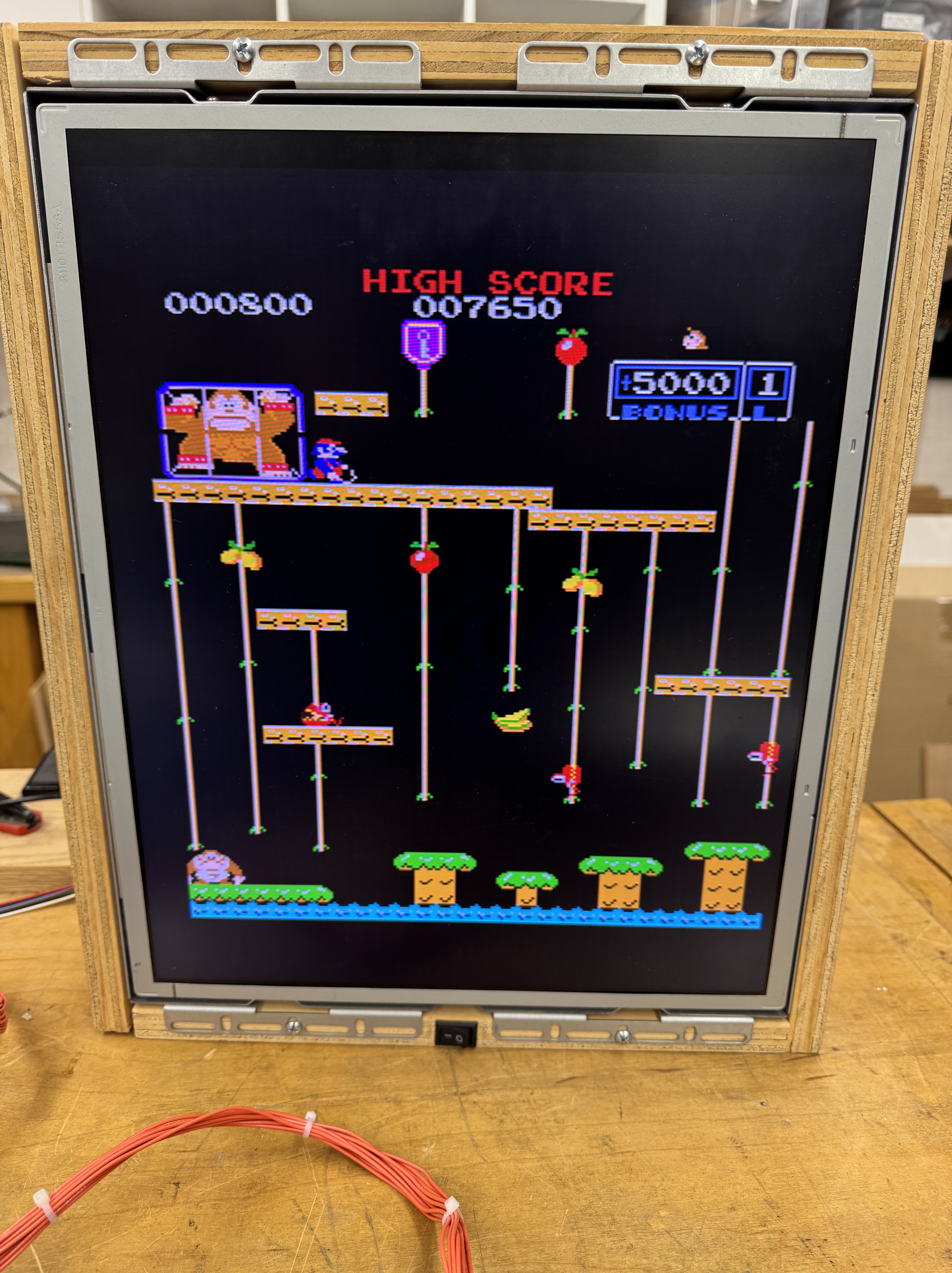
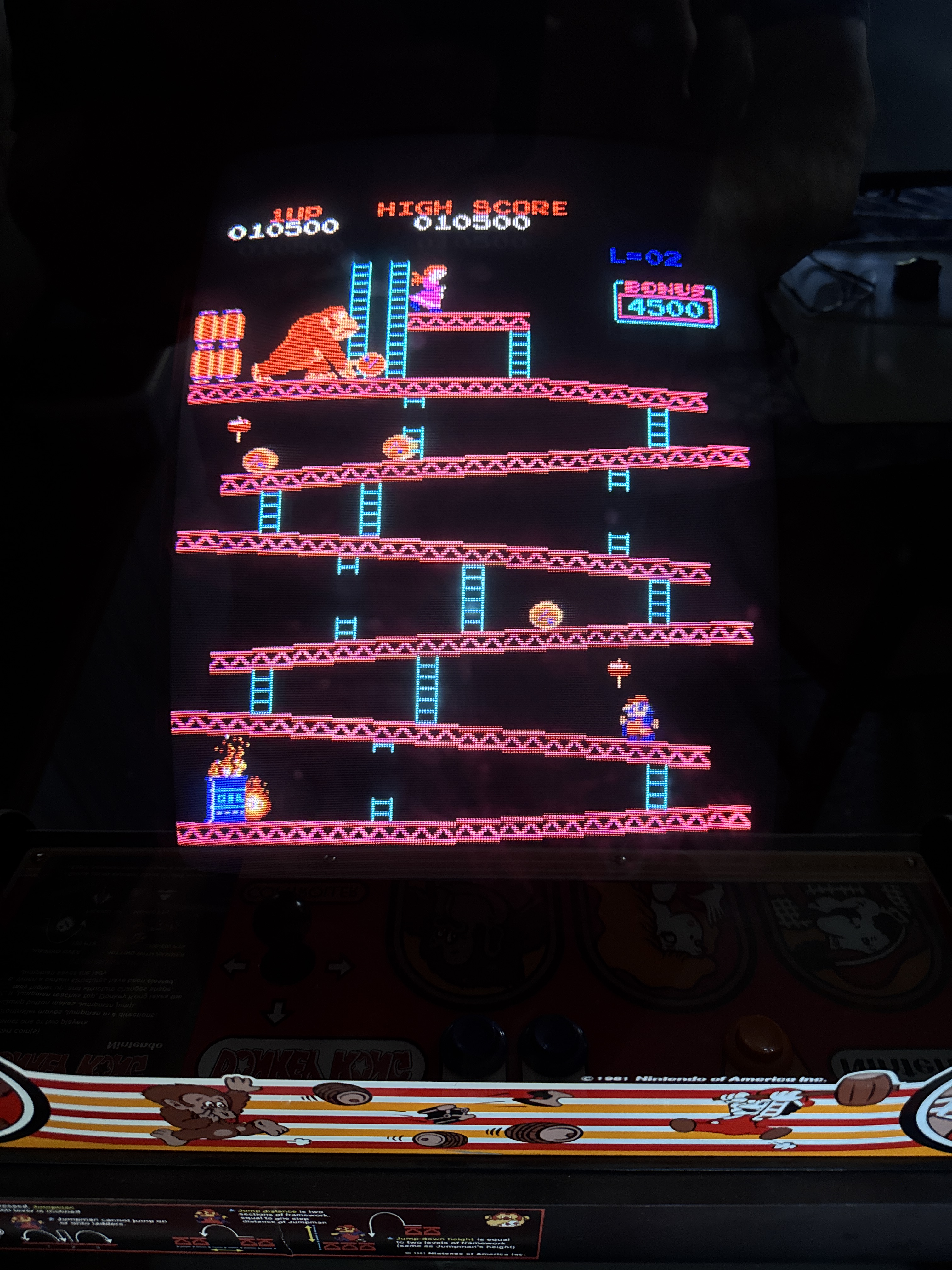
Once up and running..

Notice the blue dots above the ladder.. This little line of video glitch fades away after a minute or two.. I really did not want to try to ‘figure this one out..’ – I did a little Google Fu and found a solution! Thanks to Kaizen @ Aussiearcade. Add a 22pf ceramic cap from pin18 to ground on LS373@3K and the issue is resolved. There were a couple of references to this particular glitch in the thread.
Board works!
