
I’ve rebuilt a number of these now, but have not really documented them. I was fortunate to be able to pick another one up a few months ago for my Gravitar cabinet and it made it to the front of the bench. Turns out it has so much wrong with it I’m not sure how it could have run long enough to have so many dead components. My current “bench” 6100 is the one that came out of my Tempest cab (scheduled for restoration). It has a clean burn free tube. It will end up being my Gravitar 6100 (#1)
WG 6100 #2


Overall very complete, just dirty with some minor Tempest burn. But once you get into it..


The low voltage section was burned up, but I always replace with a LV6100 so no problem there. R920 and a few others were charred. While testing all the transistors and diodes, I found that D702 was shorted.
All of the frame transistors checked good and the fuses were all good and of the correct size – doesn’t seem possible, does it? I will remove and clean up all the frame transistors and snug up their socket connections.
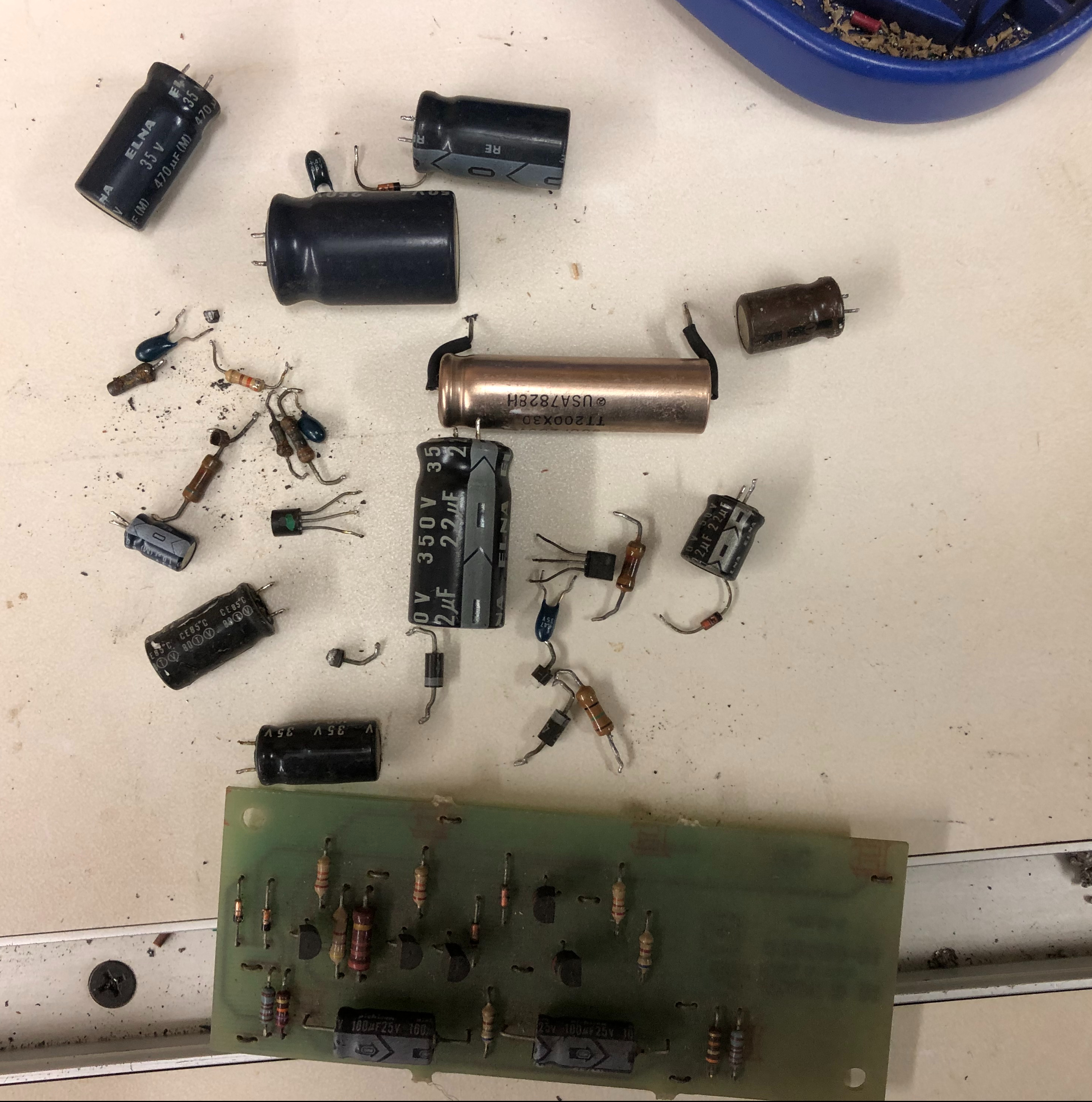
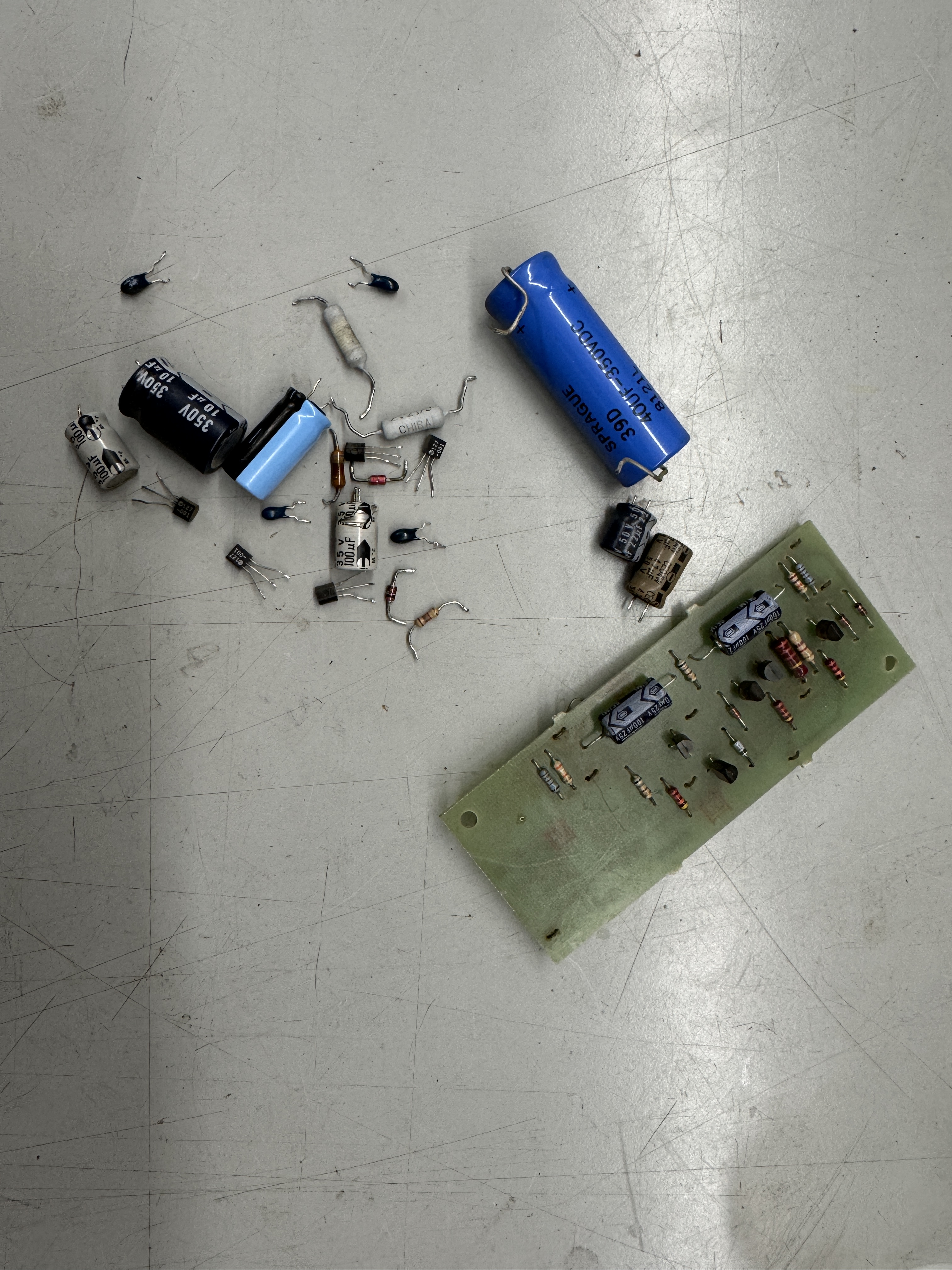
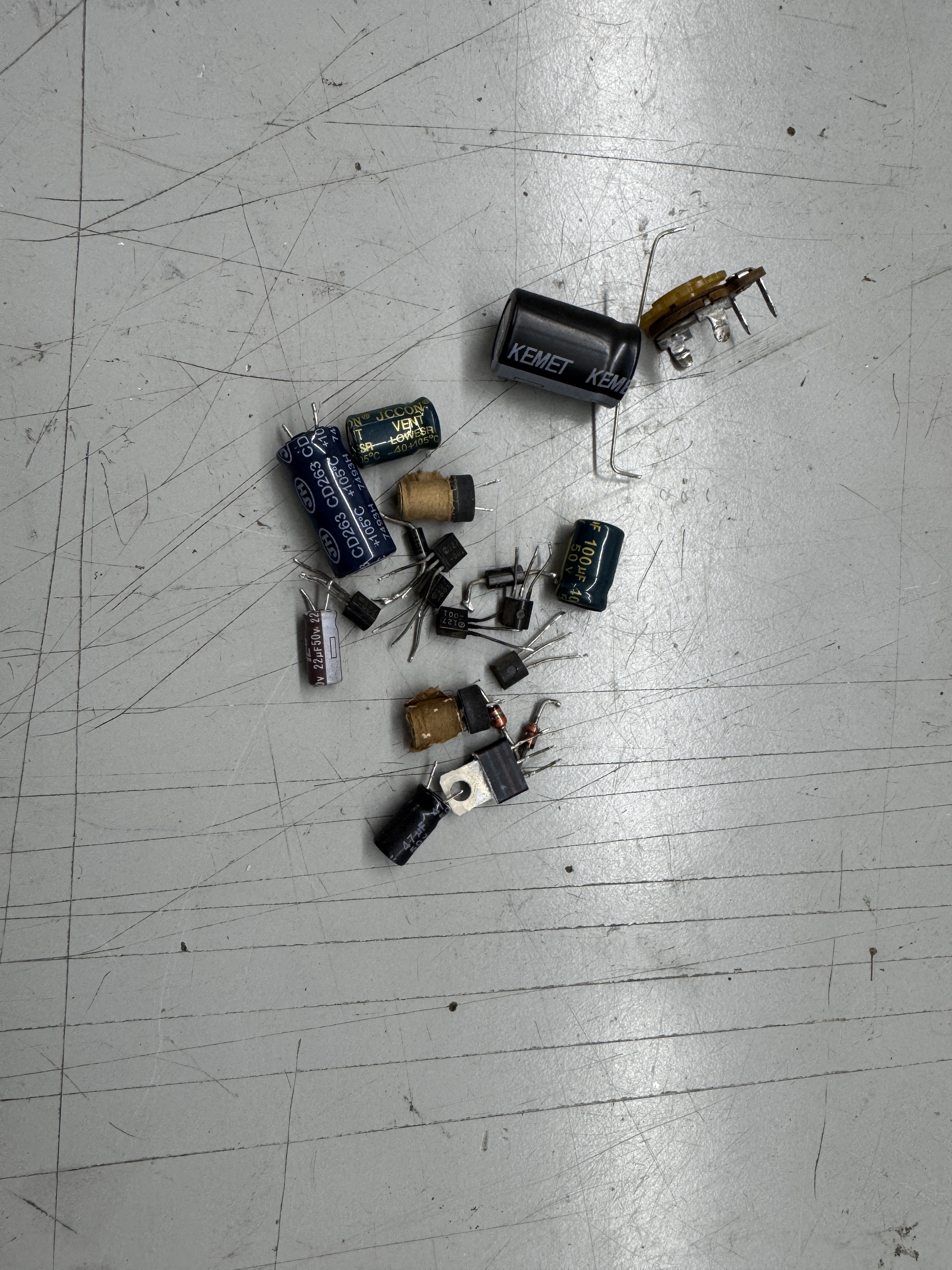
Here is pretty much all of the debris removed from the chassis. Fried diodes, toasty resistors and the caps which just get replaced.

Here it is cleaned up with all the dead components replaced, etc.. Much better!! The pins had been reflowed previously, however I wire brushed and reflowed them again since a few of them looked a bit suspect. I removed the input protection board – it’s more likely to cause problems then fix any.. R600/R700 (1.2K 1/4W 2%) R606/R706 (2.2K 1/2W 5%) need to be populated to complete the elimination of the input protection board.

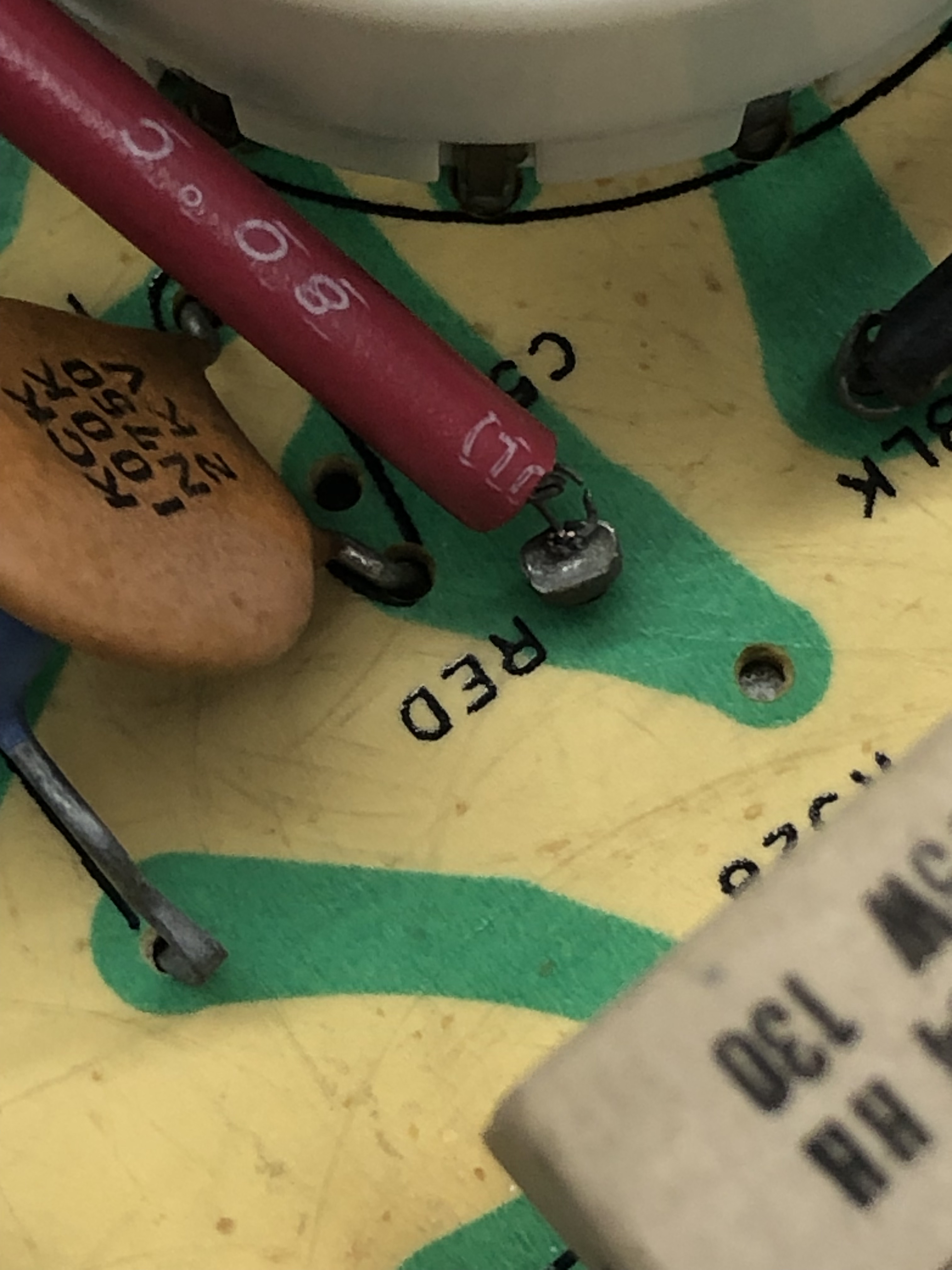
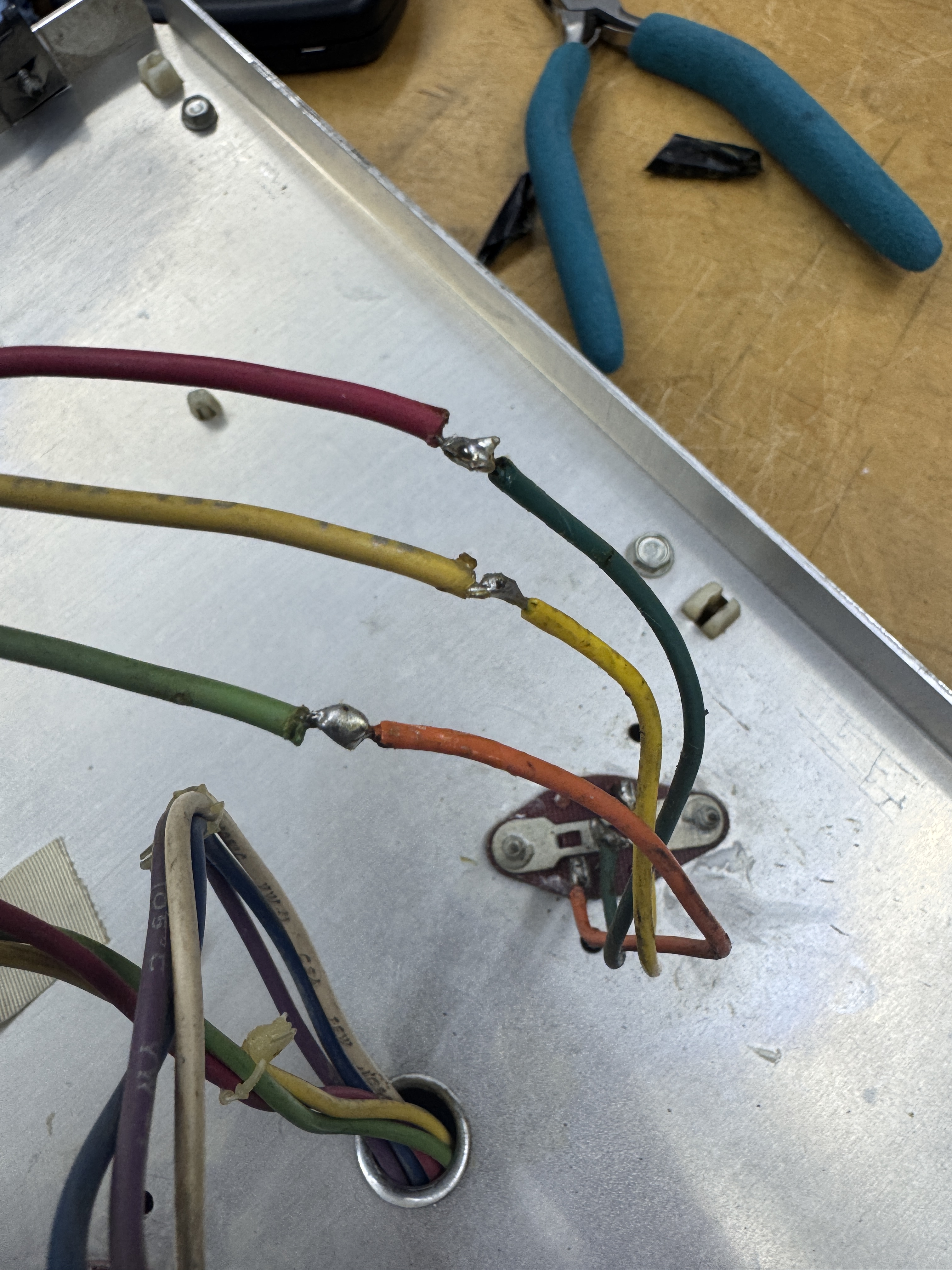
The neck board was just as dirty and the red wire was hanging on by a single strand. These wires tend to get corrosion/oxidation that creeps up under the insulation. After stripping it and trying to tin it.. The solder just doesn’t want to stick. I scraped the surface of the strands with an Exacto to get a little shine on them and using just flux – heat and flux the wire to clean it. The flux bubbles up and helps etch off the corrosion. It works pretty good after a few repeats. It now took tinning and will solder correctly to the PCB.
The high voltage section was in pretty bad shape too…


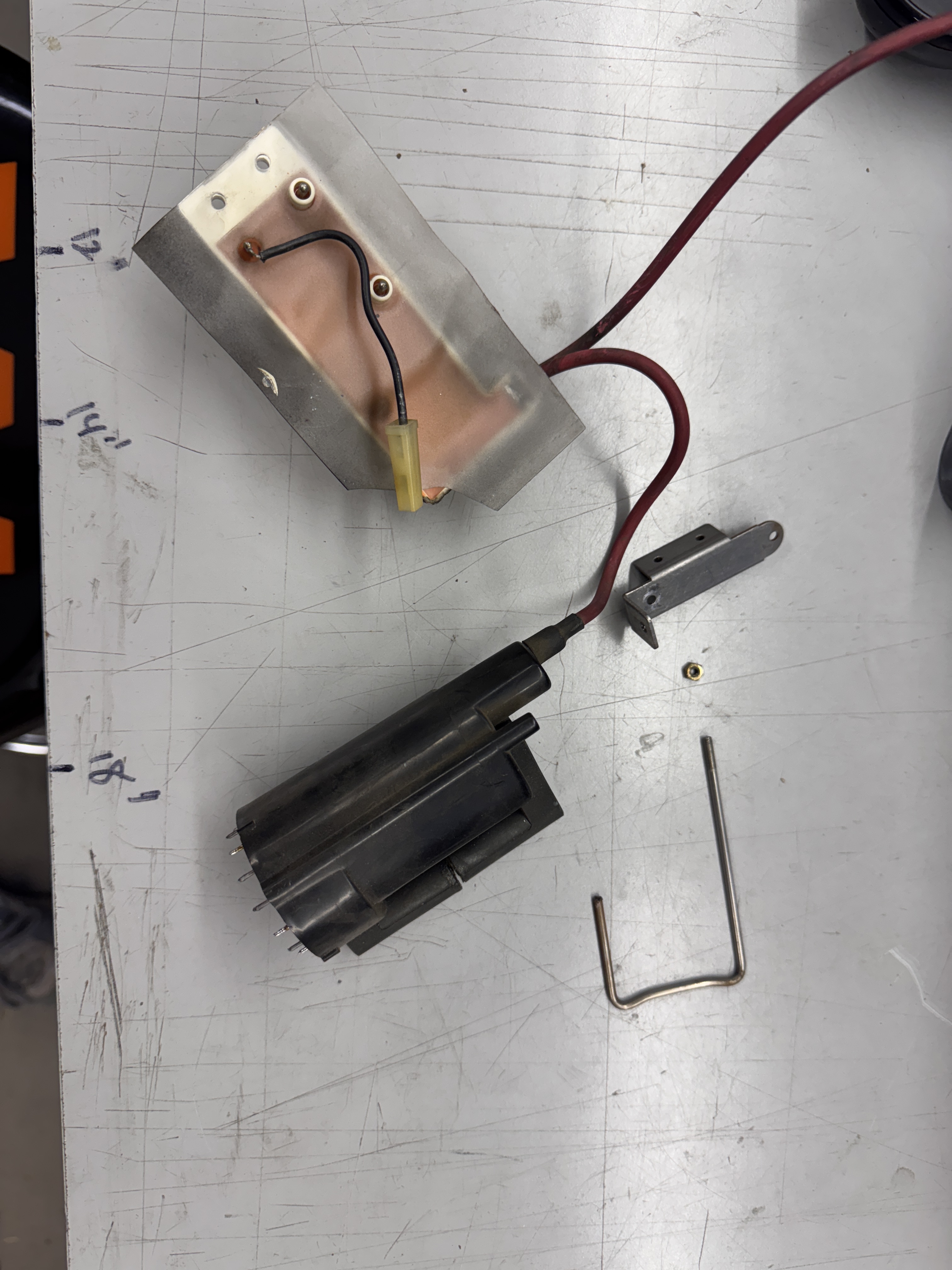
Bad or burned were: R920, R912, R906, ZD901 (replaced ZD900 too) plus the caps. Ground wire on focus block broke. The “U” bolt on the HV coil was broken. I posted a thread on KLOV a while back detailing how to fabricate a replacement for my 4600 and it has received a lot of love over time. The glue on the ferrite failed – a couple drops of epoxy will fix that.
Replacing the U bolt for the 6100 is the same however I have a few better pics to show the work.
The U-bolt needs to be non-magnetic, the original was stainless steel. I found 3/32″ stainless steel rod which is a perfect replacement for the original. That and a 4-40 cutting die and you can make your own.


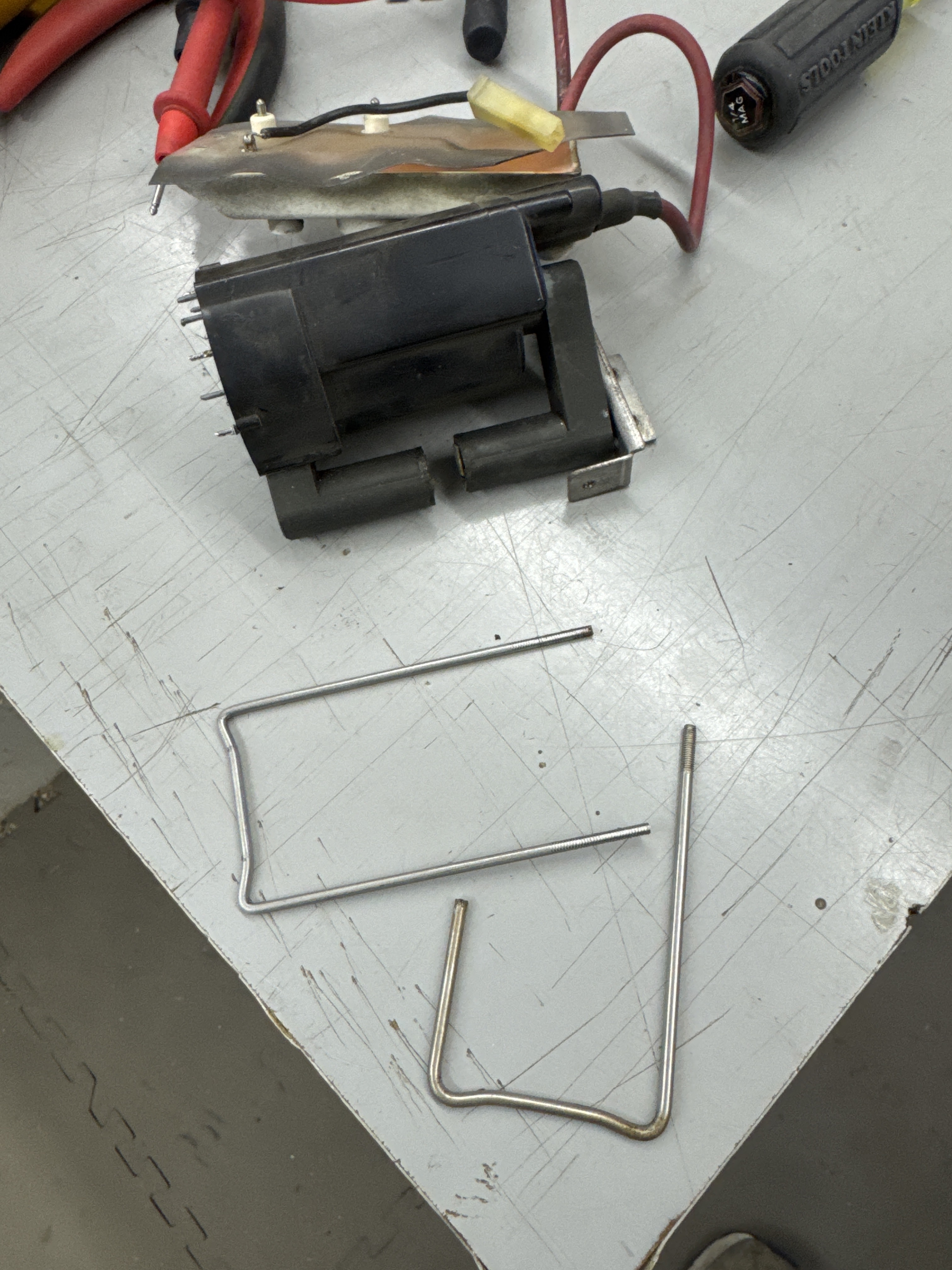
The originals have curled bends for the corners. My assumption is these were put in to keep the metal from contacting the corner of the ferrite which is very brittle. I chipped one accidentally fiddling with all of this. The goal is to have the U bolt pull the ferrite together from the flat end – not by the corners. 3/32″ stainless steel is not as easy to bend as it looks. I marked the rod and put initial bends in to match the original. It’s pretty easy to get the rod out of a 2 dimensional plane. Holding it with a vise helps to get it flat again. I finished the bends with needle nose and linesman pliers.


Once fitted – cut to length – just a little longer than the bracket. The die is tapered which makes it self threading. A little cutting oil and a large socket gets you clean threaded rod. A large socket makes it pretty easy. Just keep it oiled. I had brass 4-40 nuts, use those or stainless (non-magnetic). The original U bold was metric (it seems) I was not able to reuse the original nuts and didn’t want to bother finding a metric die.


I added a couple drops of 5 min epoxy to the ferrite to glue it back together.
Once I recapped the boards and replaced all of the bad parts and added the four resistors that eliminate the input protection board.. I used @andrewb’s World Famous “How to bring up a 6100 color vector monitor” which steps you through reducing the blast radius if you missed something. A must read for before power up.
Quick high level summary of the major steps:
- Test all frame transistors via their IDC connectors
- Test voltages on LV6100 with only degauss coil connected
- Power deflection board with no input signal (Spot killer should be on)
- Power deflection board with known working game board – listen for vector chatter
- Power up deflection and HV unit – no game board – check voltage with HV probe
- Power up complete system and adjust

Deflection system running great! No issues that I can hear or see. I like to test deflection with Tempest pcbs. Tempest generates a very distinct sound pattern which ends with a sort of revving up low to high speed chatter/whine that coincides with the Tempest logo growing full size on the screen. Once I hear that I know the deflection system is fully operational. Tempest also has the reset button on the PCB. Hold it down and make sure the spot killer comes on to verify that circuit.
Once my HV unit was back together – powered up and verified ~19K at the anode. Connected up Tempest.

Chassis works!
WG 6100 #3 – HV Unit only
Got just an HV unit in which I’m pretty sure came from an operator haul at some point. Has plenty wrong with it. I forgot to take more ‘before’ pics. However..
Triage:
- Missing some components – ZD901, focus ground wire & plastic shield, HV retaining bolt, outer cage
- Determined R901 and R907 were wrong (prior work).
- They were 1.2 ohms
- Should have been 2.2 ohms
- Getting replaced with 3.9 ohm 3W (per FAQ/Mods)
- Edge connector was completely broken away from the foil
- R919 was burned up
- Some surface corrosion

Here is the HV board completed.
- Cleaned and removed bad components
- Remove an assortment of odd-ball caps and then recapped
- ZD900,ZD901 – got replaced
- R901 and R907 replaced with correct resistors
- R919 was burned up – replaced
- Edge connector was blackened as part of the overall oxidation on this cage
- Cleaned and reenforced connections to traces
- Someone replaced the HV coil at some point, but it appears to be the NOS one from Arcadeshop
- Replaced missing focus block ground wire and plastic shield
- Replaced missing HV coil bolt
- Checked all the diodes, transistors, etc.
Put it in my bench 6100 and it ran for about 20 minutes and then it quietly died. I checked and no HV. After not seeing anything burned up. I tested the output on the 555 timer and there was no clock. Replaced it and it’s back up and running. Will do extra burn in testing on this one.
HV Works!
WG 6100 #4 – Received a full chassis and an extra HV unit

Got all of this – Deflection board, 2 HV cages, neck board and monitor frames (which mattered in this case!) – each of these had some issue.
Deflection board: lots going on with it.
- Broken white wire from harness
- Replaced LV section with an LV6100
- Replaced tantalum caps
- Q603 traces were broken, had to repair heatsink mount
- Verified all transistors, diodes and power resistors.
- Washed board
- Other small repairs
Once all of this was done – Came up clean.
HV Unit #1 – Had tape on it said ‘squealed’


I’ve run into this a number of times now. Busted U-bolt. Each time I get faster at making them. It is the root cause of squealing.
Other items:
- Busted red wire
- R907 was way out of spec. 25 ohms vs. 3.1 ohms
- Needed full recap – had really cheap ones installed
- The screen/focus Molex connector had a bad pin on the red wire (crimped new one on)
- Both wires had new sections spliced in, but had been covered with black tape.
- Removed tape and used heat shrink tubing
- Washed board
- Adjust HV
HV works
HV Unit #2 – Marked “Steve” – No HV
- Unit has a replacement Chinese HV coil
- Has newer caps, not the best quaility – but I’m out of kits at the moment
- Determined Q901 was bad – it caused the no HV
Spend a lot if time trying to get the colors dialed in and bright. Determined the cheap HV coil (flyback) is likely the root cause of the issues. If I get bright colors, I get retrace lines just as the Tempest LOGO turns on full during attract mode. I’d replace the HV coil and recap to make this one 100%.
HV Unit works.
Neck Board:
- Replaced its one CAP from the kit
- Had a busted wire
- Focus wire broke off
Didn’t work the first time powered on.. Neck boards never give an issue. I rechecked everything and also re-tensioned the pins in the neck connector. Second time was a charm. Neck board works.
Did spend some time setting all the colors and cutoffs. It should just need minor adjustment when it gets back to it’s primary tube.
Monitor Frames: Even these had issues
- The lower frame had a bad 2N3792
- The side frame had a replacement socket (no problem) but it was held in place with #6 wood screw that shorted to the frame (problem)
- Once that was corrected – the same transistor was out of spec
The transistor was not allowing full X deflection to the right (this is the X axis on Tempest) as seen in the video. Maybe being shorted killed it.. Replaced.
Monitor frame works!
WG 6100 #5 – Received a chassis with a Tempest repair
This one was pretty blown up. When I work on them, if they don’t have a LV6100 power supply, they get one. I also recap them.


The red wire to the neck board is almost always hanging by a single strand. R919 is pretty toasty here. Spent a few hours on it..
Chassis works!
WG 6100 #6 – Received a full chassis and frame with a Star Wars repair

First time receiving an entire monitor frame with the chassis (no tube) – but after working on it.. this is a really good way to get a 6100 up and running again. I was able to test and reseat all of the bottlecap transistors and moving my tube from my test 6100 to this was easy.


This chassis had many things wrong with it.
- ZD901, ZD902 were 2 diodes tented together (does that work?)
- D902 had the wrong diode and it was bad.
- D702 was shorted
- R508 on the neck board was broken
- Red wire to neck board weak
- Trace broken on HV board
- Boards got washed
- Plus much more..


This had burned up at some point.. The pin came out green and greasy. Replaced both sides.


Cracked trace at the solder joint of the HV coil. Easy to miss.


Much better..
WG 6100 #7 – Word got out that I work on these at work, colleague has a Star Wars that has been down for 6 years.. I took his PCB (was fine) ARII, Transformer brick and the 6100.
It’s still amazing they can get this bad..


Had some prior work, extra dusty, burned up LV section and burned up resistors in the HV unit. It D702 was shorted.
Now and then I bring it all in the house and sit at my desk to rebuild these..


Most of the debris, parts heading to the sink for washing and I sometimes use the holder when working on these.. Especially at my desk.
Once all the maintenance was done – I normally test the deflection board with Tempest because it has a particular vector chatter. This time it sounded a bit off. Once I got the HV unit in – things were wrong. Chased my tail a bit at first – on the LV6100 – one of the voltage regulators was getting burning hot and shutting down.. Long story short.


I looked at this a number of times – and like the ketchup in the front row of the fridge – missed it. Cold solder joint. Boards all cleaned of flux.. Adjusted to the owners Star Wars board.
Chassis works!
WG6100 #8 – Received a chassis for repair
Owner told me he had recapped, added LV6100 and done a bunch of work – but it was blowing fuses. Found out later it had its wiring chewed up and he replaced it.. Best way to get them right is to get everything but the tube.

The wiring replacement job with new Molex connectors was very well done. Once I realized that was the case I verified there were no mistakes, etc. None of the new Molex connectors had the key pin inserts – I added them to all of the new connections.
Working through the deflection board:
- D602 – was shorted
- F100, F101 – blown. Right amperage – but were normal blow vs. slow blow
- Had 3 bad bottlecaps – Q605, Q606, Q102
- Removed the input protection board
- Added keys to all of the new Molex connectors

I have a list of items I check/replace as part of the rebuild.. But overall this is a nice deflection board.


The red wire on the neck board must take a beating, the majority of them I’ve seen are hanging by a single wire..

R905 in the HV unit was just toasty enough to get replaced. R901/R907 got replacement 3.9 ohm resistors per the FAQ. Replaced ZD900/901.

Ran for 3 hours. Chassis works!
WG 6100 #9 – HV Unit with Alan-1 Deflection and transistor pack
Owner reported R901 keeps burning up in the HV unit.

Here is where it started. Many components have been replaced – there is a lot of prior work. I didn’t get a good angle – but many of the replaced parts are floating way off the board, mostly diodes and the resistors. Many of the new blue resistors are very over wattage from what I can tell. My concern with that is they can allow other components to burn up during a failure (or worse) when they should go first..
That all said – it took a few hours to go back and basically test every single part (I printed the BOM and checked it off one part at a time). It I wasn’t sure about a diode – I replaced it and I right sized all of the resistors and put in new caps.

I removed the flyback just because it made the work simpler. The back and front got cleaned up and this is more like a standard HV unit now. I tested everything as it came apart and it all seemed to be fine. Hard to be 100% sure if there were an issues on this board before I worked on it.
Q900 tested good on diode check with my meter – but I picked up a new tester recently and I’ve been trying it on different ‘suspect’ parts.


I’ve been trying it out and comparing known bad to known good transistors, diodes etc. to get a feel for how it works. Q900 is the BU409 that is on the outside of the HV cage next to the focus block. It is also in line with R901 that has been burning up per the owner. The FAQ also mentions R901 burnups with Q900 involvement. You can test and get numbers on the unit – but you can also test on a PC and graph the data.

The graph hFE = 140 is the bad transistor. I tested 3 others and they were all at hFE = 20. The hFE measures current gain.. I’m 90% sure the transistor was breaking down under load and blowing up the rest of the board. Can’t really be positive because of the prior work – I did not power up the board as it was received..


The neck board needed a little help. It was mostly dirty – but one of the ground wires was missing and I think 80% of them have the red wire hanging by a single strand.
Tested the HV unit with the OG deflection and transistors because I’ve never seen the Alan-1 setup in person. HV worked perfect first power up.. Added in the Alan-1.

The Alan-1 deflection board seems to closely resemble the original. The LV section is not there and many of the components are beefier. No surface mount parts – so that means it can be serviced a little easier if needed. If I had one design item – It would be nice if the fan unit had build in variable speed based on temperature.. Out on the bench it is pretty loud. Maybe inside a cabinet it is not as noticeable.
HV Works!
WG 6100 #10 – Full monitor chassis in for repair

Best way to get your 6100 repaired – send everything except the tube.
Removing the tube is easy: 4-bolts and disconnect the yoke. The store it safely out of the way. If you break the tube.. you are out of luck. They are exceptionally difficult to find and expensive to replace.
Someone worked on this at some point – the deflection board had been recapped and the bottlecaps are all new. I still checked all of them (no assumptions on prior work).. The 3A fuses were wrong, but it all bench checked properly.

The streak continues – red wire on the neck board hanging by a single strand. Everything else checked out.


The HV unit had never been touched. It had a number of issues. Original (or very old caps) The HV adjustment pot was broken. R920 had failed open and there were a number of other burned up parts. When I have this much work to do on them – I remove the HV transformer and set it aside. It is easier that the whole thing flopping around on the bench as I test and replace components.


Much better – chassis works!
WG 6100 #11 – Full monitor chassis in for repair
Person I worked with in the past said he had a 6100 for me to rebuild. He acquired one that sat in a warehouse for 20+ years and sent this pic. Two 24v power supplies to replace the low voltage section. It must have worked..

Here is what was actually shipped. To repair these correctly – I really need the bottom and side panels that have the bottlecap transistors. Shipped this way can save some money as compared to shipping the entire frame (tube removed). It is only 6 screws to get the frame apart.
On 6100’s – I never plug them in and see what’s happening – I just start tearing them down and inspecting. This one is getting an LV6100 and a cap kit, which they all get unless they had them already. I also have a list of components that are routinely replace to assist in reliability.

This one had a few burned up resistors and I found Q805 was bad which looked to be part of the input protection circuit. I few of the resistors had been replaced with very oversized parts. I put them all back the way the should be. Somewhere in all of this I also replaced a busted POT on the neck board. All of the bottlecap transistors get removed, cleaned, the socket gets tensioned and they get Silpad insulators.


Here is part of the connections for power from the switchers.. Removing everything… Who knows why they even did it? This is one of the rare – non burned up LV sections.. I typically wash monitor chassis too. This area is super clean.

Depending on how much work is needed, I’ll pull the HV transformer off and work on the HV PCB like this – it’s just easier to handle. R920, R905, R910 – VERY oversized.. Cleaned it up and replaced a few more burned up resistors.


This one cleaned up really nice. After performing all the maintenance and bringing it back on-line ..
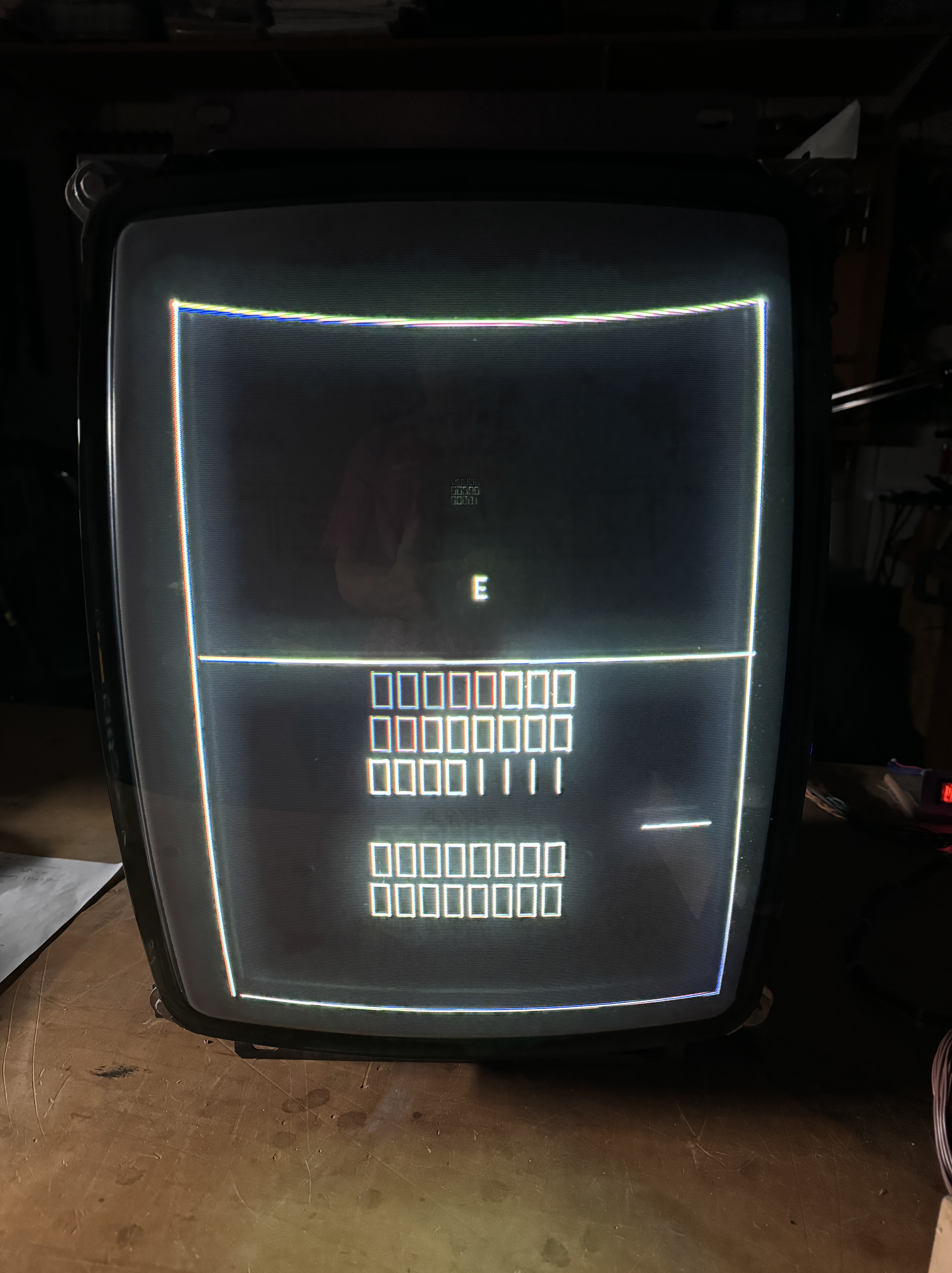
I could not get it to adjust properly on the Y axis.. Moving Y center or Y size would cause the image to bump up across the top line – but not expand.. This pointed to 2N3716/Q705 – but I wanted to see if I could test it too. With my transistor tester..
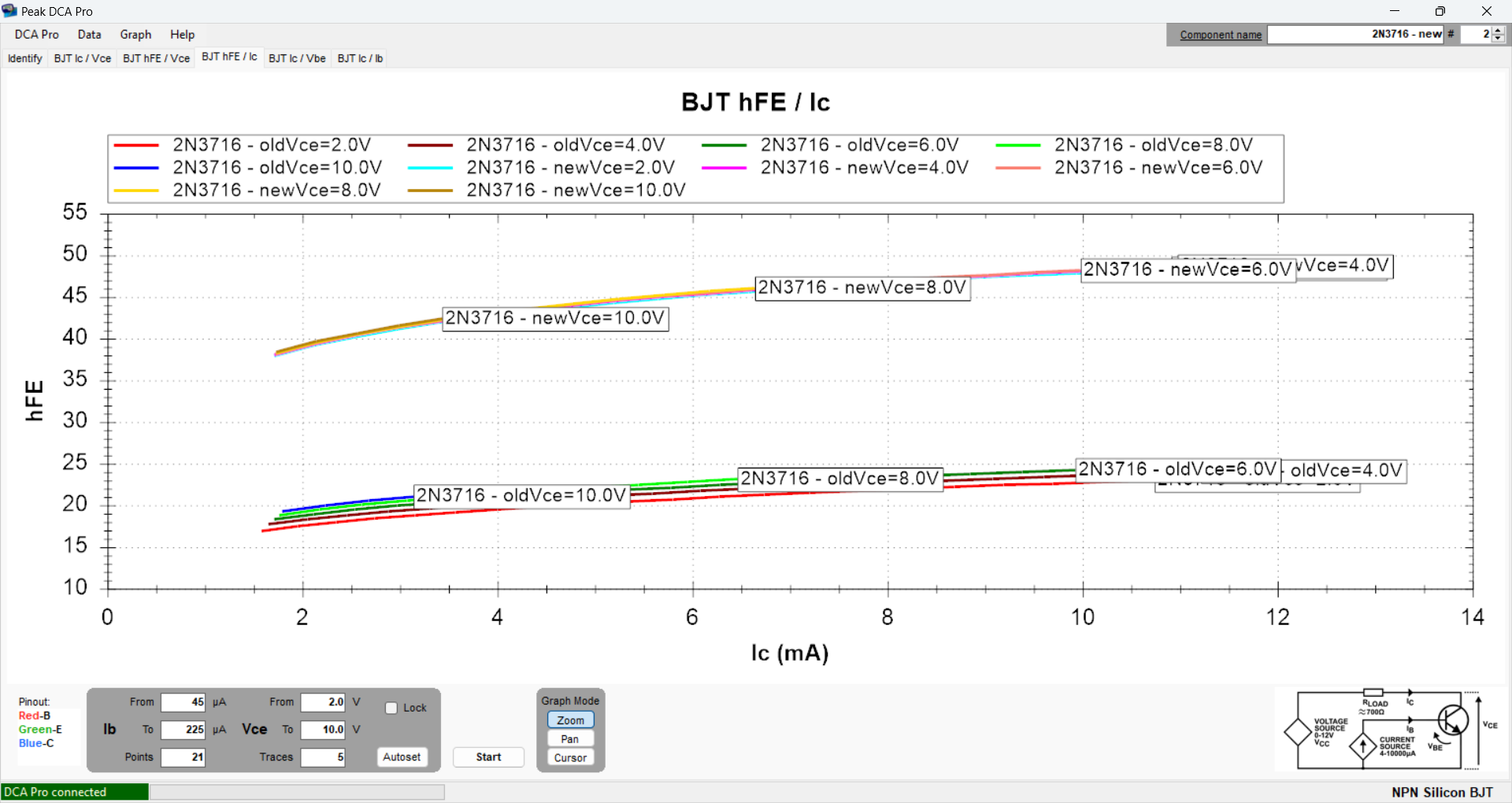

I ran the charts and these two stood out. You can see 2N3716 old vs. new. The old one was not generating enough gain. The important part here is the transistor can check good with a standard meter (i.e. normal voltage drops, not shorted, not open, etc.) It drifted out of spec over the years. It’s one of the reasons I need the monitor frame to test and make sure the chassis is 100%!

Chassis works!
WG 6100 #12 – Full monitor chassis in for repair
This one showed up as a full frame/chassis

I work against a checklist I developed on these. It takes a few hours of tearing down and rebuilding before I ever add power to one.
The neck and deflection board got cleaned and rebuilt/recapped. There are a number of checks that happen to them. I’ll focus on the more visible issues ..

The HV board had a number of problems. Obviously the burned up area needed attention. Another notable find was R901, R907 were only 1 ohm and visibly overheated. I haven’t seen reference to this low a value in these. The FAQ and other guides recommend 3.9 ohm, 3W resistors. They got replaced. R906 was pretty toasty as were a couple others..

Once it all went back together it looked pretty good.
I went through the normal power up sequence. When I got to the HV unit, I had my HV probe connected and powered up.. It only showed about 3KV.. Pretty quickly I noticed the black and red wires on the connector going into the focus block started to smoke.. It all happened pretty quick and I powered off.
I little cross checking on the HV transformer…


Here is Pin 11 (ground) checking resistance against Pin 9. The bad one shows 2.465K ohms. A new HV unit – open line (as it should be!) After replacing the HV transformer..

Chassis works!
WG 6100 #13 – Full monitor chassis in for repair

This one showed up complete (w/o tube).. Not 100% necessary – but it did make things simpler since I did not have to fully disassemble my bench monitor. Owner reported that the HV had gone out, he replaced the LV section with an LV6100 – then decided to send it out to me.
Initial inspection revealed the following issues:


Broken red wire on bottlecap connector, degauss coil thermister cold solder joints and completely broken loose, yellow wire from video Molex connector broken away, red wire on neck board broken away (the streak continues), the U-bolt on the HV transformer was broken (I bet this one whined when it ran) and the purple wire had broken away from the transistor socket and was tucked under the metal tab..
First step is to remove all the caps and components that I upgrade as part of a rebuild (a few diodes and transistors).. inspect .. etc..


I’ve covered this before, I bend a replacement from stainless, cut to size and thread for 4-40 stainless bolts. Put it all back together..
The other notable items were:


R907 was burned open (and the victim of the LV section dying on the deflection board. It then caused no HV) R919, R920 and R906 were all toasty. Finally.. the debris field.. Input protection board also removed.
Standard maintenance includes removing all of the bottlecap transistors, cleaning up the paste and using Silpads for the insulation barrier as well as tightening the socket connections. Washing the boards and cleaning up the chassis in general.

Chassis works!
WG 6100 #14 – Full monitor chassis in for repair

Best way to get a 6100 for repair. Having all the bottlecap transistors makes getting these much more reliable. All of them get removed, I clean off all the goop and re-bed with silpads. The contacts get tightened and the connections get checked.


On this one, broken wires. At some point someone cut the wires going through the base. Why would they do that? They at least soldered them together, but then used black tape. I removed the tape, unsoldered the connections, added heat shrink tubing and resoldered.


Other notable items: HV transformer cracked and flexing it showed movement – didn’t even try it. It got replaced. The low voltage section was burned up – I always replace this section with the LV6100. Cold solder joints on the deflection board.


Fully rebuilt HV unit – it had a number of burned up components. G902 was completely missing? It also did not have an HV cover, so we got a replacement. Finally – here are all the parts that got replaced out of necessity or checklist items that commonly fail.

Chassis works!
WG 6100 #15 – Full monitor chassis in for repair
This one came in as just a deflection and HV chassis. No frames or neck board.

It was really dirty – 95% of the time I wash the monitor chassis anyway. One I cleaned it. I ran down my checklist of ‘standard’ parts to replace and validate before applying power.


The Arcadeshop LV6100 has failed. Voltages are not even close to where they should be. Replaced with the LV6100 from Arcade Parts and Repair. It is a sturdier and simpler design. From here the deflection board ‘sounded’ like it was working. I test with a Tempest board and the vector chatter has a very specific pattern I’ve gotten used to. I test the deflection this way before moving on to the HV cage. D106 was shorted – part of the degauss circuit. Updated some other parts.


The HV cage got some updated caps and power resistors. Both got some diodes and resistors replaced that were burned up. The HV also did not have a power connection. I fabricated one not knowing if it existed or not. R906 was burned up. R901,907 got upgraded.
Once I got it all set up – I was getting deflection chatter and no video.

This was not visible at first. Had to flex the board and the resistor on the deflection board to get this to appear. Reflowed it.

Chassis works!
WG 6100 #16 – Full monitor chassis in for repair
Received a 6100 chassis that has not worked in a while based on the looks of the components. There were a number of issues.


R703, R711 were burned up.. Bottlecap transistor wires broken off. Hard to see in these pics, but most of them were soldered into their sockets. Normally I remove, clean and reinstall them with silpads, but I did not want to risk ruining all of the sockets. They all tested good in place.


The HV power connector had its wire repaired by soldering it to the pin at some point.. It was hanging by 2 strands. Both got repinned properly. Fuses were missing and the ones that were there were incorrect.
It had been recapped at some point. Some of them were good Nichicon caps and others were some weird off brand. I replaced all of the odd-balls.

Here is a cap from the HV board… Same value, but the prior one was very different in size. Same on the neck board. Replaced the HV adjustment pot.


The last part I almost missed. I was having a tough time getting the colors adjusted and the HV seemed to be unstable. The GRAY ground wire on the neck board was completely missing. Once I realized that the adjustments were much easier. Finally, most of the debris after the rebuild.
Chassis works!
WG 6100 #17 – Full monitor chassis in for repair

Received a lot of parts on this one. Owner has an Alan-1 Deflection and Transistor kit. He wanted the originals put back into working condition and sent all the parts.

I’m assuming this HV cage was not the one working with the Alan-1 parts. The cans were blown completely off of these caps. I did recap the HV board… The deflection board had been done in the past.
Overall this was a very nice 6100. I’ve had some really beat up ones come in the past.
On the deflection board – there were a few issues. Q603 open B-C and D602 shorted. Everything got washed and cleaned up..
Here is the debris from the rebuild.
Original Chassis works!
