
*** Newest Entries always added to the bottom ***
Received a board in for repair – not my first one, just the first one since I started documenting them.

Initial inspection:
- Clipped pin @C5 – this turned out to be a speedup hack. I put it back to normal.
- Bad ROM @N/P3
- Beeped out a bad RAM @E2
- Notice the dark spots @M4, N4, P4, R4.. Something is up here..


This board also had an interesting mod. Someone replaced the 4 RAMs @M4, N4, P4, R4 with a 6116 @R3. Here are a few jumpers on the back and they cut a few traces. It all seemed to work however.
After a full maintenance cycle and making the repairs…

Game played and tested out for a few days..
After one last power cycle – It complained about a bad RAM @R4 (the 6116 mod). Doing some verification – the LS245 @P2 showed a dead pin stuck high for D4. The ROM @N/P3 got corrupted and the RAM was a bit flaky. The LS245 had a hot spot below it like the old RAM. Not sure if it was the original issue with this board or there is something else happening. Replaced all the parts and the board has been running fine..
Board works!
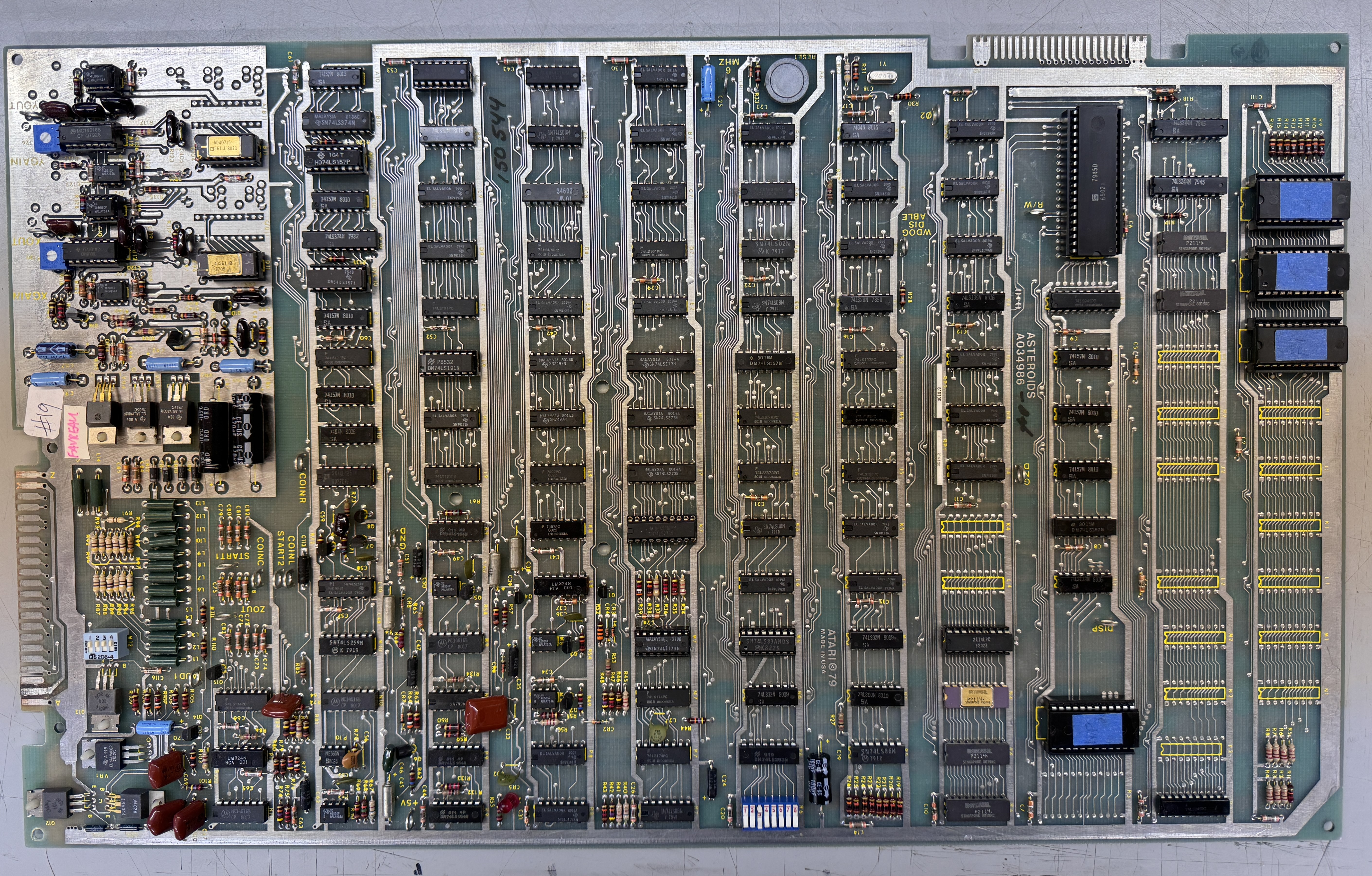
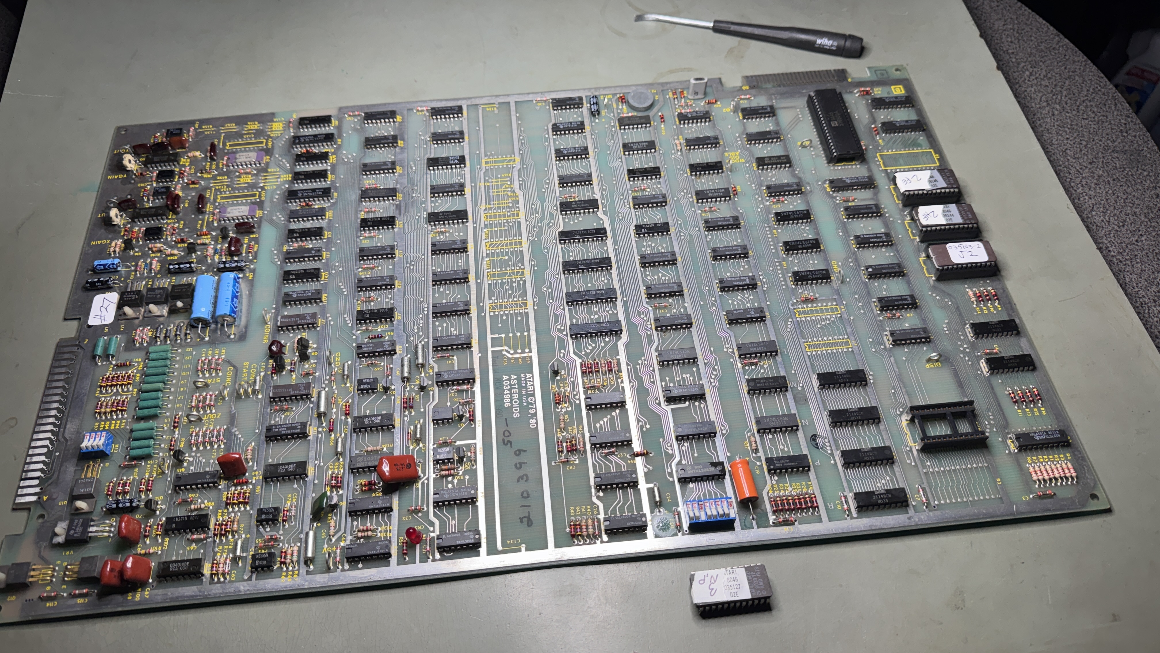
Board #2 – Received an Asteroids board for repair. After washing….

Board cleaned up nicely
Initial inspection:
- Big ceramic cap broken off in analog section @C91 (replaced the matching one @C94)
- Burned up edge connector
- Crystal can loose
- Bad CPU socket
- Bad socket @C1
- First of the Asteroids I’ve worked on that had PROMs. The only set installed made up the 035144-2 ROM. I Tarnx’d them and left them original.
Washed, cleaned and inspected the board. Lots of IC, etc. on the back with very long pins. Some I clipped to prevent shorting and some I straightened.


Repaired burned edge connector. Re-tinned. Results are same thickness as the other fingers.
RAM checked good. The ROM was flakey until I discovered the bad socket @C1. Pin12 was missing causing the ROM to corrupt the bus when inserted. Replaced CPU socket, ROM socket, Crystal and the big orange caps.

Board works! Thump Thump worked. Fire was squeaky and most of the other sounds were missing. Bad LM7812 in the power section. Replaced it.
Board works!
Board #3 – Board in for repair
I thought I had worked on early revision boards in the past.. But not so sure now. I went out and printed the first revision schematics that matched up better than the set I had.

Initial inspection:
- Lots of prior work – none turned out to be an issue
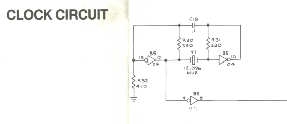
- Had the wrong crystal (12 MHz) and it was broken off
- Some trace repairs
- Vector generator was dead.. Simple HALT test not working.
Cleaned up chip legs, etc..
ROM, RAM all checked good. After considerable hunting for the cause of the dead vector circuit.
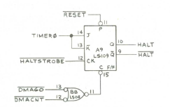
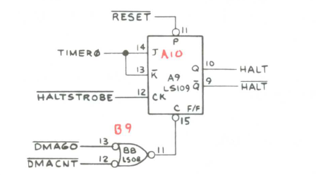
I was getting the getting HALT on Pin10, but I was NOT getting HALT signal on Pin9.. As a result – the state machine was “half running” causing confusing signals around the area.
- Replaced LS109 @A10
- Replaced crystal with proper 12.096MHz
Board works!
Board #4 – Board in for repair
Initial inspection:
- Some prior work – none turned out to be an issue
- Missing crystal
- Has a good edge connector repair, but with exposed copper. Will tin it.
- Missing chip @M10 (4016B analog switch)
- Had a non-matching ROM installed 144-04.
- It checked bad AND was mismatched to the set.
Cleaned up chip legs, etc..
All RAM checked good.
Once ROM and RAM checked good – tested the Vector Generator – all checked good.
Hard to see – game plays but all of the graphics are very compressed. It appeared very analog at first and I did a log of checking in the analog section.. But it seemed to be running properly. Digging into the VG Section…

After poking around for a while – the Inverter 7404 @H11 was not working … and therefore no clock to the Y counters.
Once the game was running.. there was no thrust sound and the new 4016B at M10 was burning hot! Whoever had worked on the board prior had pulled and socketed the 4016B and left it off… with good reason. I decided to track down the lack of thrust sound first.

I scoped my way through this part of the circuit following the noise signal into the LM324.. with nothing coming out. Replaced it. No change. At that point I checked each component around it looking for issues. When I got to R103 – it read nearly a dead short. Pulled C69 – a green gumdrop cap and R103 was fine. The cap shorted internally of course.
Replaced and thrust sound restored! After this I put the 4016B back in @M10 and it runs and normal temperature. I’ve looked at the schematic and probed all around and can’t determine how one effected the other.. But I’m guessing they were related.
Board works!
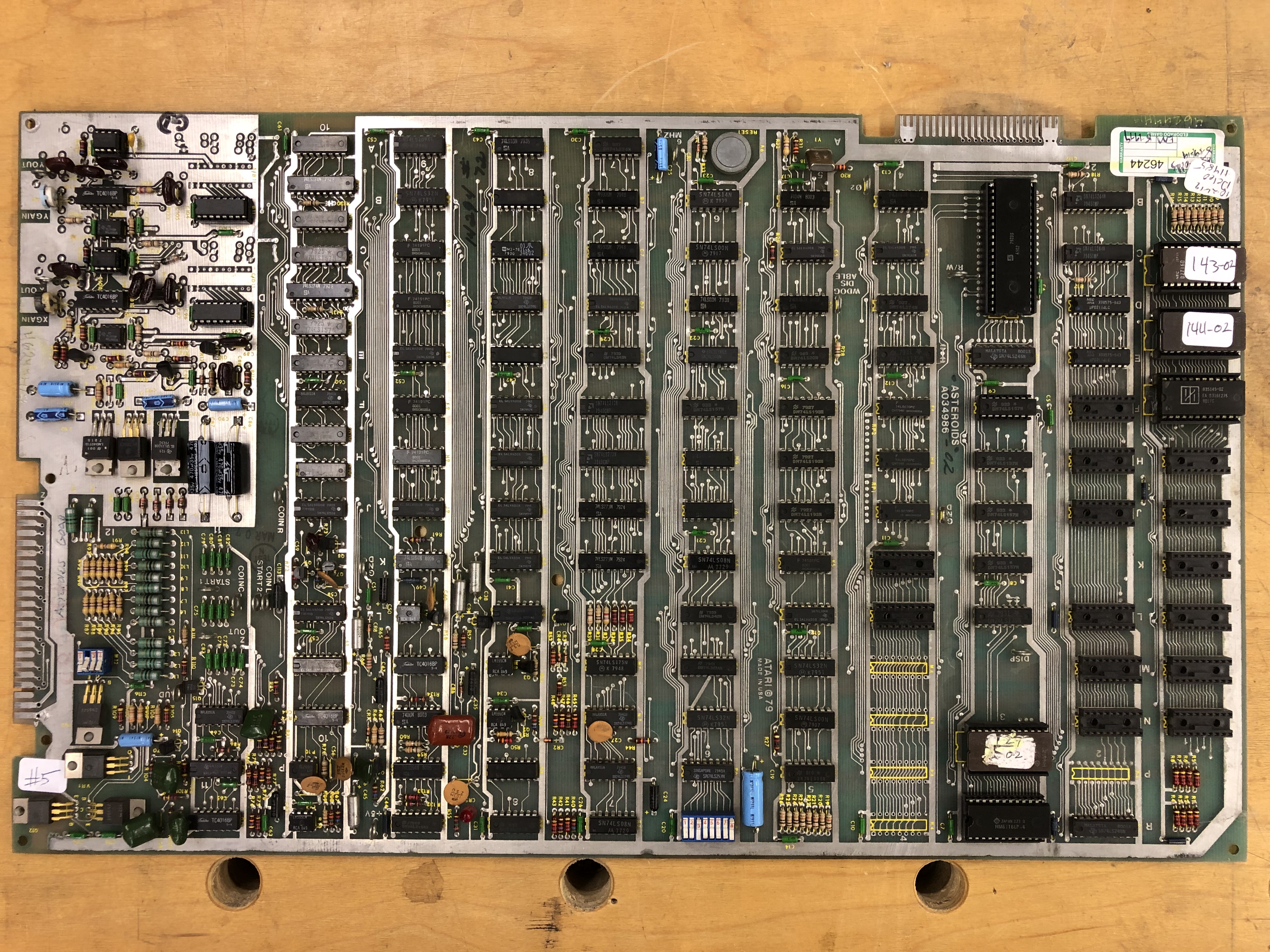
Board #5 – Board in for repair
This board had a lot of issues and I spent a fair amount of time untangling them
Initial inspection:
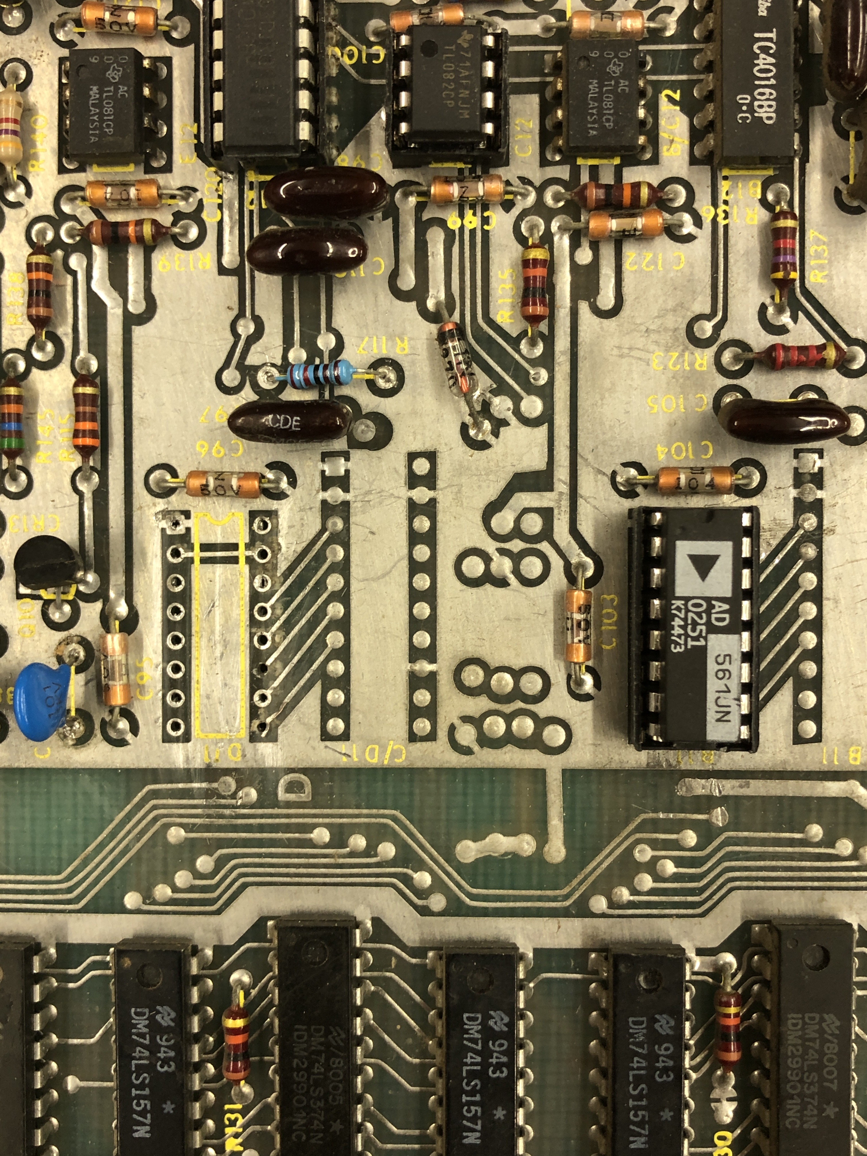
- Has a RAM mod that eliminates all of the 2114’s and replaces them with a single 6116 RAM.
- ROM 143 had a broken leg
- ROM 144 checked bad
- The VG would run HALT, but nothing else..
- Missing both DACs
- C107 was missing in the analog section
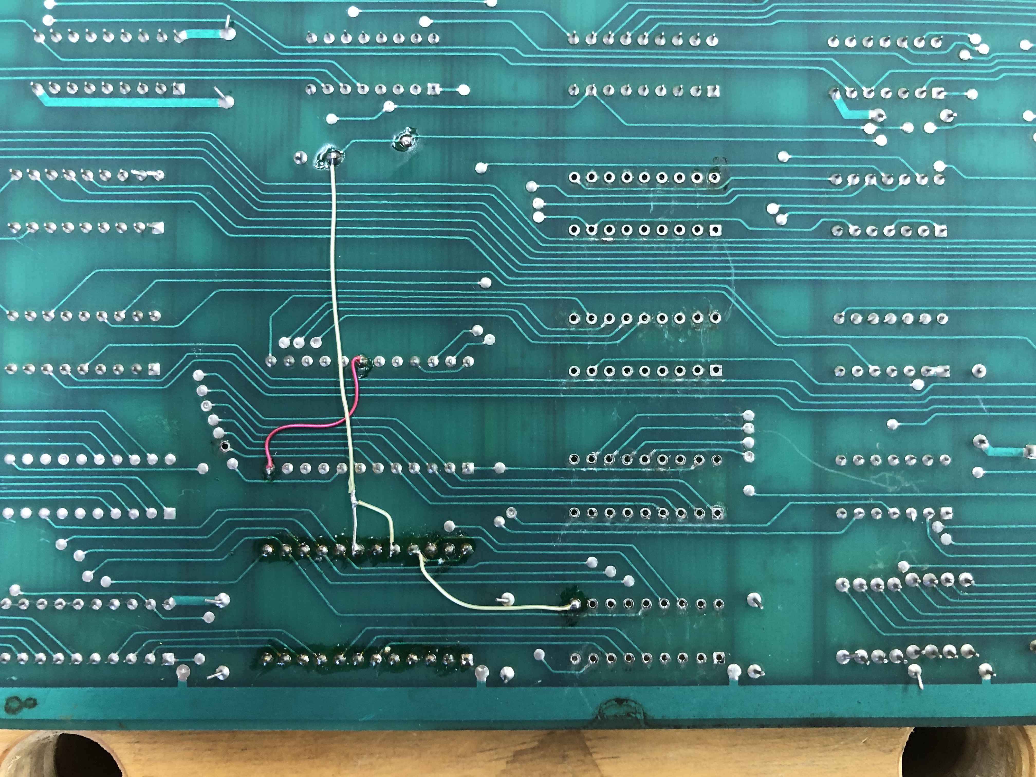
Here you can see some of the 2114 RAMs missing and the 6116 using the open socket area with a few jumpers.
Work done:
- Verified RAM
- Verifed ROM once replaced with good chips
- Replaced missing DACs
- Replaced missing C107
With the board running – it appeared the LS42 @E8 was outputting on Pin2,3 – but the signals looked really bad. Replaced it – but no joy..
After finding dead vector generator everywhere looking for control signals as the cause.
I stepped back and realized the counters were not actually being clocked. LS08 @B8 had good inputs and no output. Replaced LS08 and VG sprang to life! All VG commands running.
Once done – the graphics were distorted. The TL082’s @C12, A12 had been socked and replaced at some point – however both were bad or poor quality.. Replaced them to fix the graphics.
The last item on this board was something I didn’t notice until after it was running (and it was a cause of confusion). The watchdog circuit was broken. Easy to diagnose. I could use the diag switch and go from test grid to game – but it would just hang between modes. Had to hit reset on the PCB to get it to flip.. A good test to know if your watchdog will work or not!
Tracked it to another LS08 @E6 (same Signetics chip/lot) There are 2 more on the board I’ll keep an eye on..
Board works!
Board #6 – Board in for repair
Initial inspection:
- Bad mask ROM – Don’t see too many bad ones.. But I have.
- RAM checked good
- Vector Generator will VG HALT, but will not run VG CENTER command
- Plenty of prior work
- Missing DAC @B12 (replaced)
I’ve spent a lot of time learning BattleZone and Tempest vector generators. Getting a much better feel for Asteroids now.
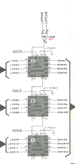
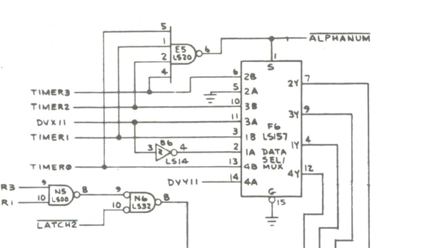
The VG HALT instruction clearly doesn’t do much of anything with the VG address space. Knowing it starts and stops is good.. If VG CENTER isn’t running – the issue is likely here some place. Clock was running this time. But the counter outputs didn’t look right.
Replacing the LS193@J5 fixed VG CENTER in terms of it now HALT’ed.. But it’s timing was off. Replacing LS193 @H5 fixed all the commands and their timing.
Whoever worked on this before was on the right track.. Just didn’t follow through.. They had pulled the LS193 @J5.. But they put it back..
I’ll be watching the LS193 @F5 to see if it goes. If it doesn’t after 40 hours of burn in time.. We’ll call it good.
Board works!
Board #7 – Board in for repair
Reported partial collapse and broken vectors. Shipfire and saucerfire bad.
Started with full board and chip cleaning. Tarn-ex cleaned them up nicely as usual.
Initial inspection:
- RAM checked good
- ROM checked good
- VG shows a good HALT and nothing else
Working though the timing chain showed LS161@D7 to be bad. Replaced and VG is fully operational!
Tested on scope then monitor. As reported, shipfire and saucerfire were way off.
I’ve had similar issues in the past and was a bad CR3 or CR4 diode.. But they checked good. Pin 7 on the 555 timer wasn’t draining down like it does on a known good board.
Socketed the LM324 but not part of the issue. Replaced 4016 analog switch @M10 – sounds fixed. Ran 40 hours solid after repairs.
Board works!
Board #8 – Board in for repair

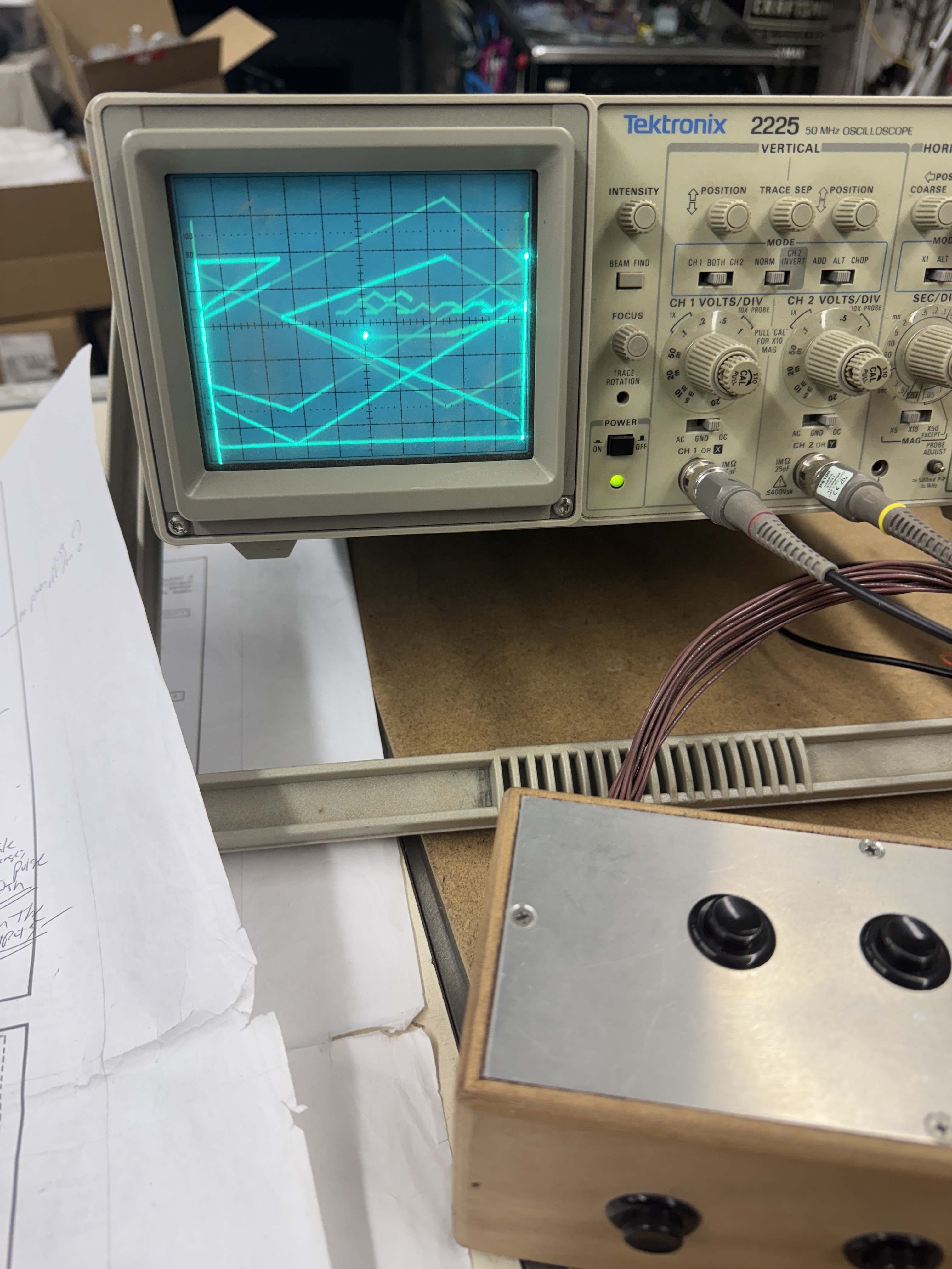
Provided with a video of board running with bad vectors – but kinda trying sometimes.
Initial inspection:
- RAM tested good
- ROM tested good
- Vector generator – stone dead – could not even get a HALT signal
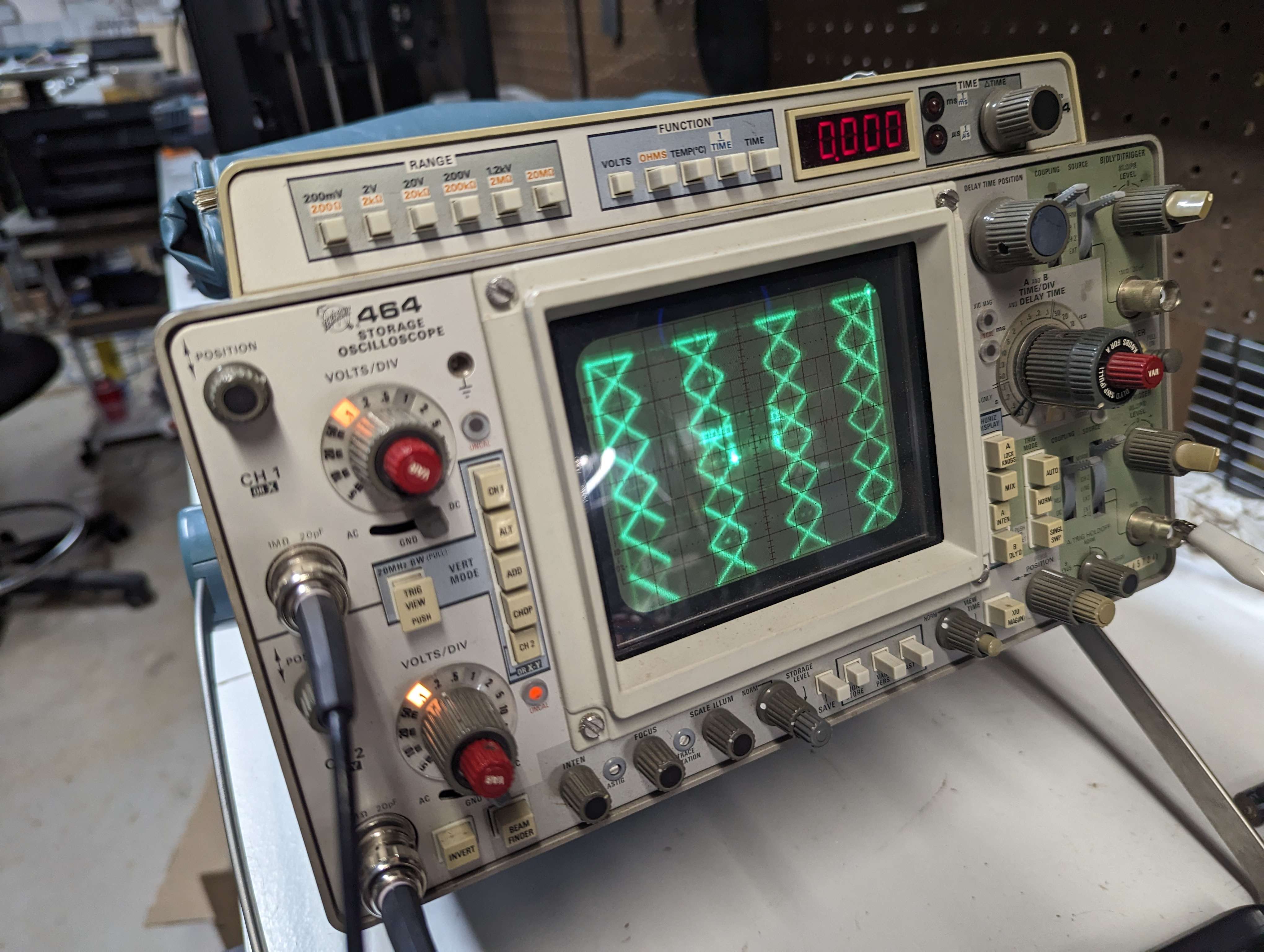
Prior to this board – I had been repairing Asteroids sitting behind my Asteroids cabinet on milk crates. Now that I have a bench harness system in place – I spent the time and built an Asteroids adapter for the bench.

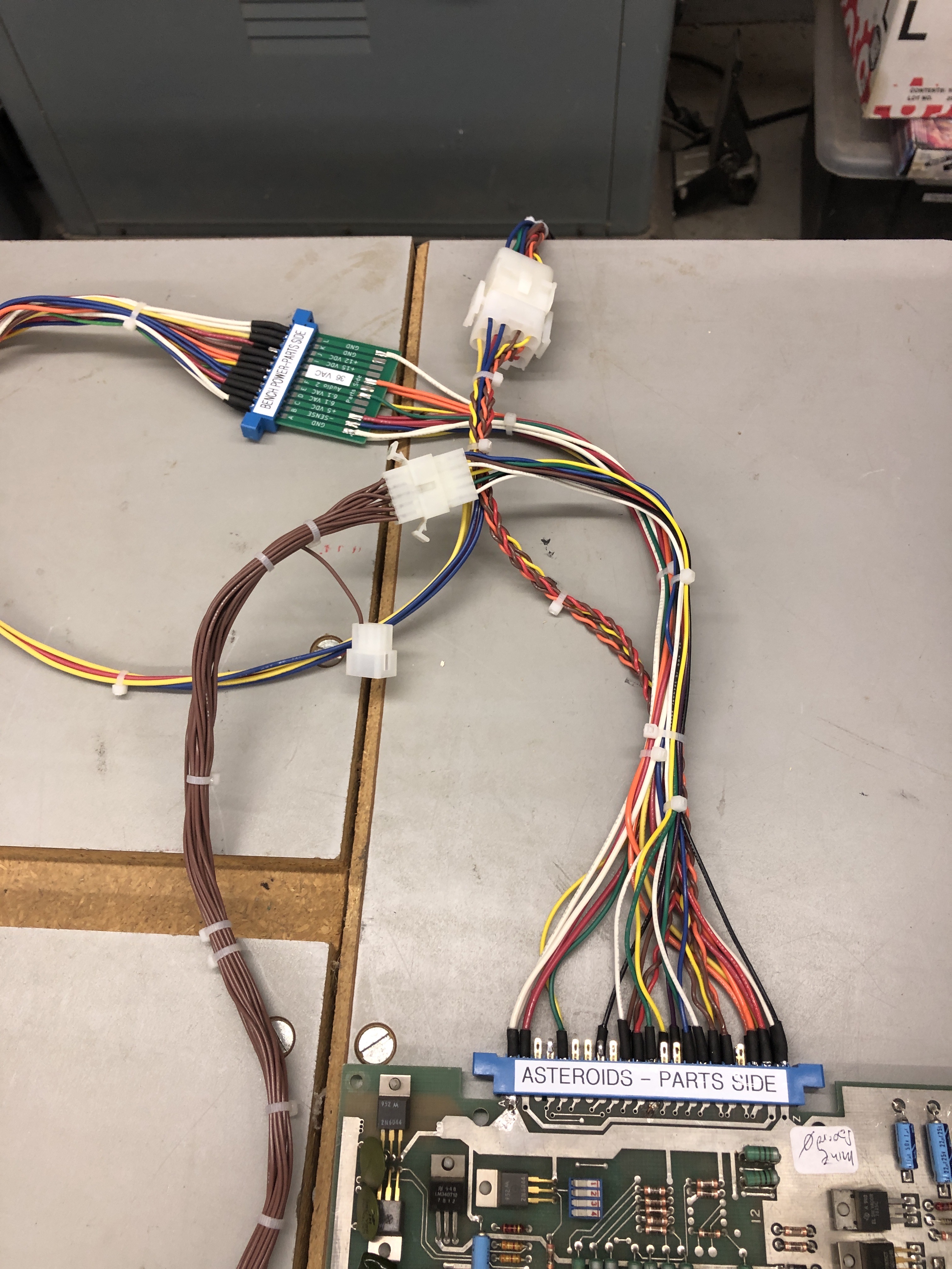
Takes a couple hours to build these up – but they give back a lot of time by not having to adjust bench supplies, etc. Plug and play.
Poking around the board – it initially looked like the LS109@A9 did not have a HALT signal that matched HALT (inverted of course). But @A9 was not the issue. Since everything was dead. It took a while to actually locate the offending chip. Finally I bumped into LS08@K6 Pin3 – no where near where I normally look for bad HALT problems.

One of the reasons it took a while is because things were ‘sorta’ firing now and then. I could get Timer outputs now and then – but the vector generator was just running ‘trashed’.
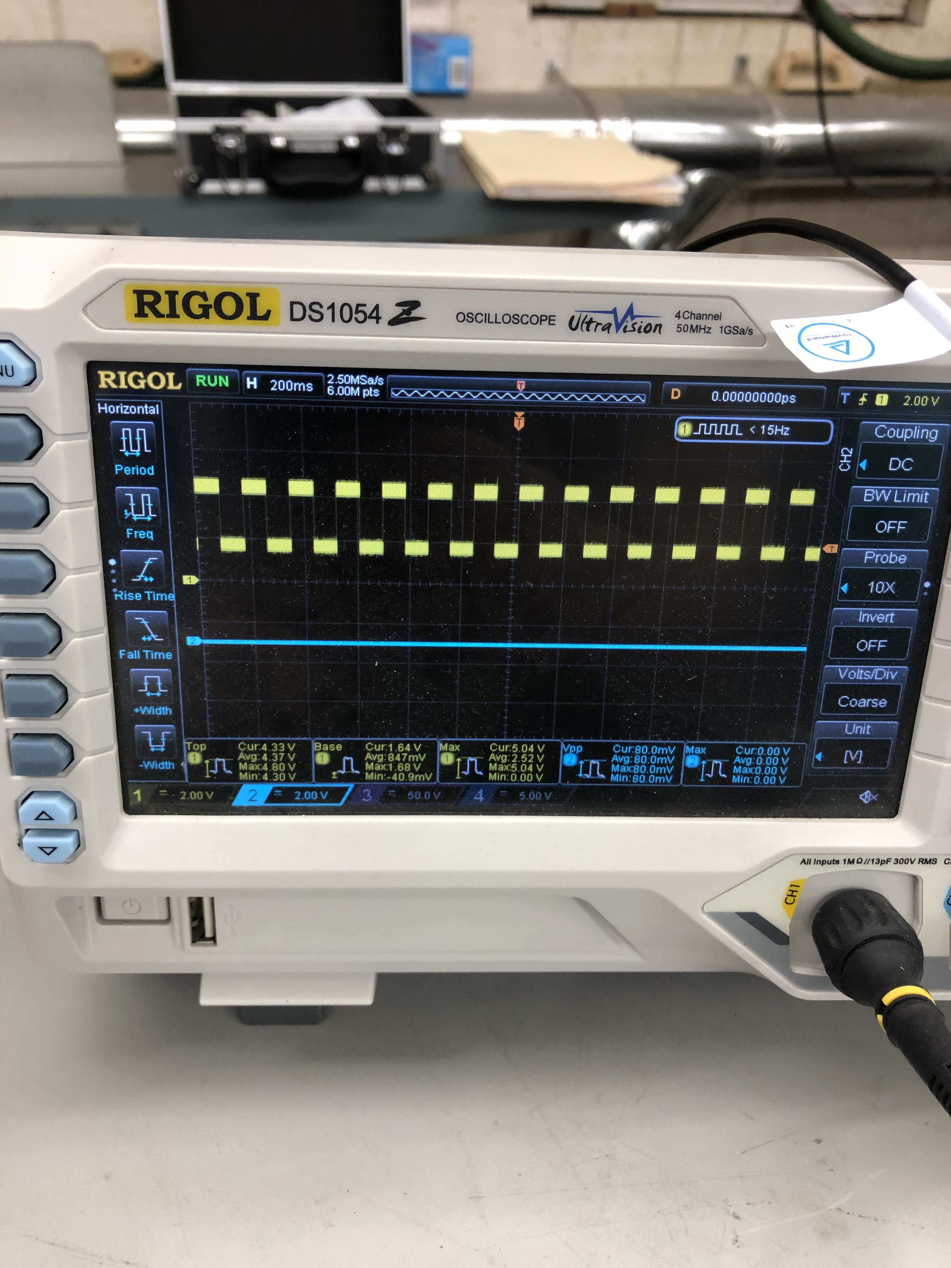

Here’s the reason. On the left – Pin3 with perfectly shaped signals – just never reaching 0 volts. Replaced LS08 on the right.
Board Works!
Board #9 – Board in for repair
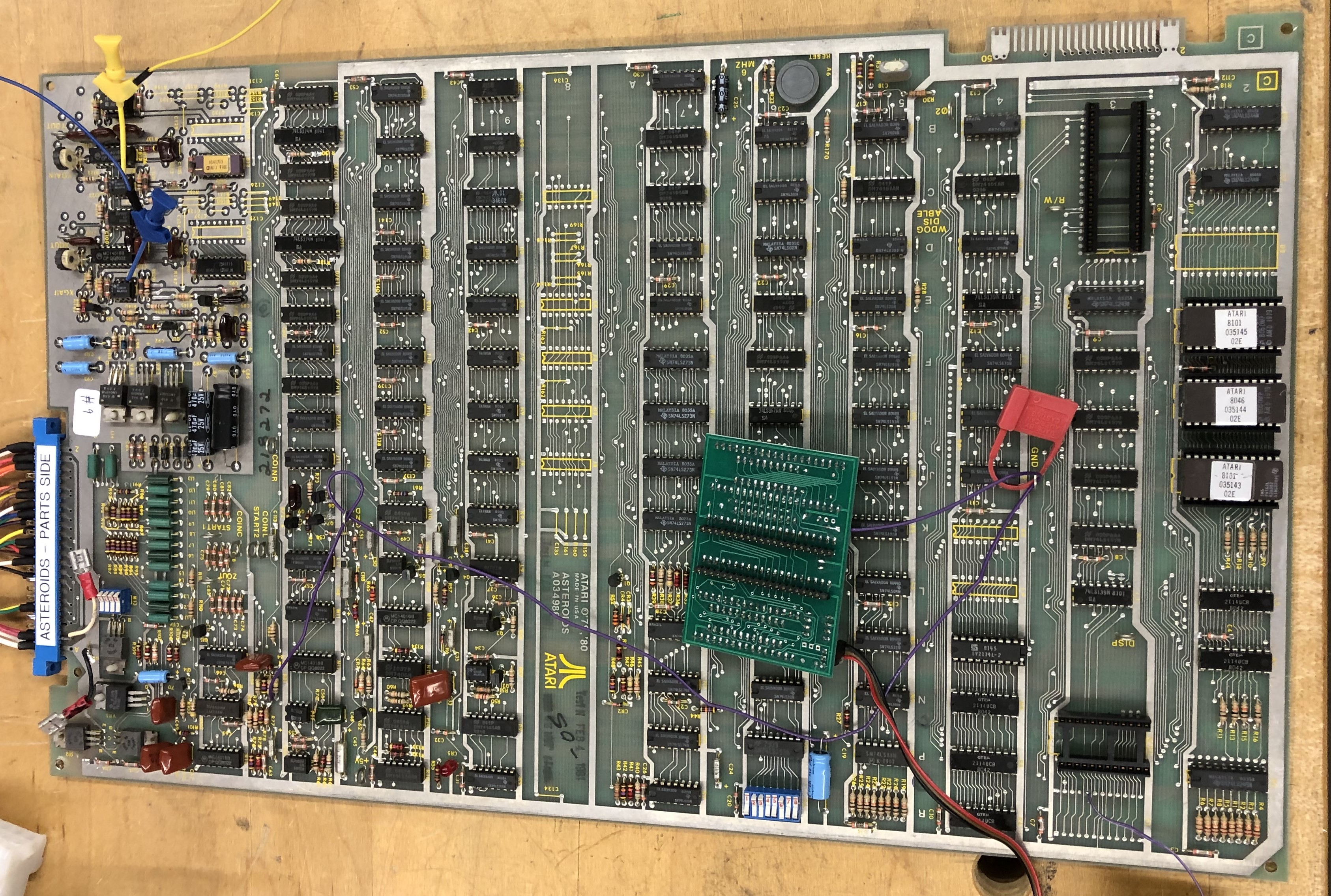
Initial inspection:
- Had to temporarily remove Braze kit to work on the board
- RAM tested good
- ROM tested good
- Vector generator tested good
- Bad Y output (to start)
Testing 4016B on the Y side showed it was pulling down the 8.2V to about 4V on pin 14. Replaced that.

While working on it I noticed the 7815 voltage regulator was really hot, even though it was outputting proper voltage.

Put a new one in after looking under it. I was having issues with the switches on that side anyway. The TL082@A12 had been socketed in the past – socket was bad.
Finally got to some test screen output:

After poking around a bit, determined the 7404@H11 appeared to have issues.


Good clock going in – bad clock coming out. I swapped the chip – but it was not the issue.

One of the LS191 counters has an issue on pin14 pulling down the clock output. Time to finish assembling and use the Leakseeker I picked up. I’ve run into this situation enough times now that a new tool could be helpful.
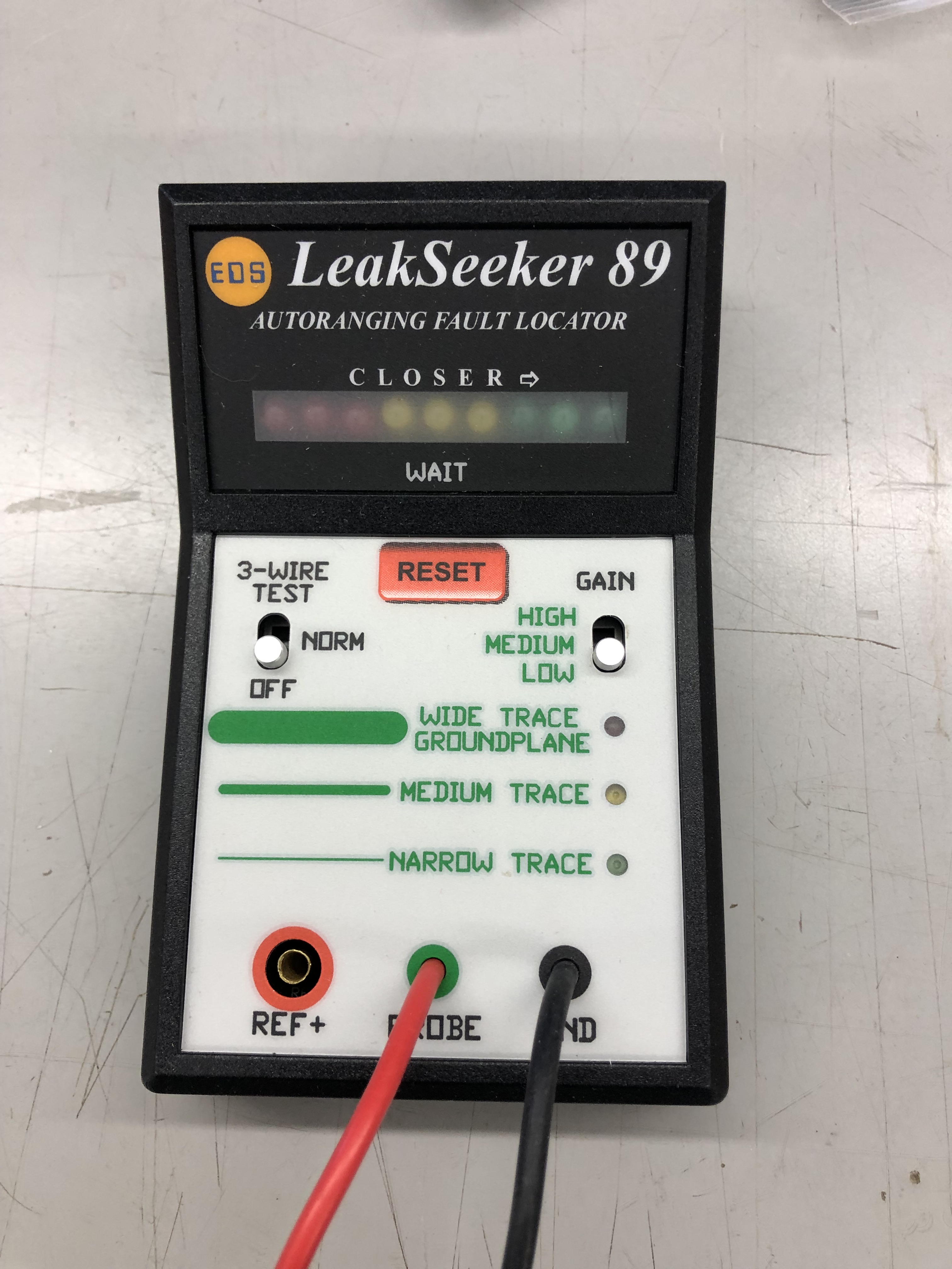

The counters in question are physically 2 inches apart and pin 14 is a straight line between them. The Leakseeker quickly determined that LS191@H10 was the likely culprit…

I’m impressed.. I’m looking forward to the next one.
The last issue was this….


Graphics distorted on the top half of the screen, but if they moved to the lower half of the screen – they corrected themselves… I was thinking it was a bad high bit on a Y counter for a while and even replaced the LS191@F10 since H10 was bad.. But no…
I should have done this sooner – I flipped it into cocktail mode to see if the problem stayed or moved.
It went away – but introduced a new distortion. Turns out I got a batch of bad analog switches mixed in with my good ones. I’d already replaced the 4016 analog switch – which is why I didn’t go back to it initially. Problem cleared up.
Board works!
Board #10 – Board in for repair
Board was very clean – connected up to scope and just the asteroids were huge.
It appeared to be a scale issue. I determined it the vector timing was only off on short draw vectors. I had powered on and off a number of times and checked the ‘scale’ signals. I then piggybacked LS14@B6 and the issue cleared.
I removed the piggybacked chip and it stayed clear. I’ve since run this board a lot and it will not fail it seems. Maybe there was a tiny short?
Board works!
Board #11 – Board in for repair
This one was a tricky one. I know the AVG of Tempest and Battlezone much better than the DVG of Asteroids.

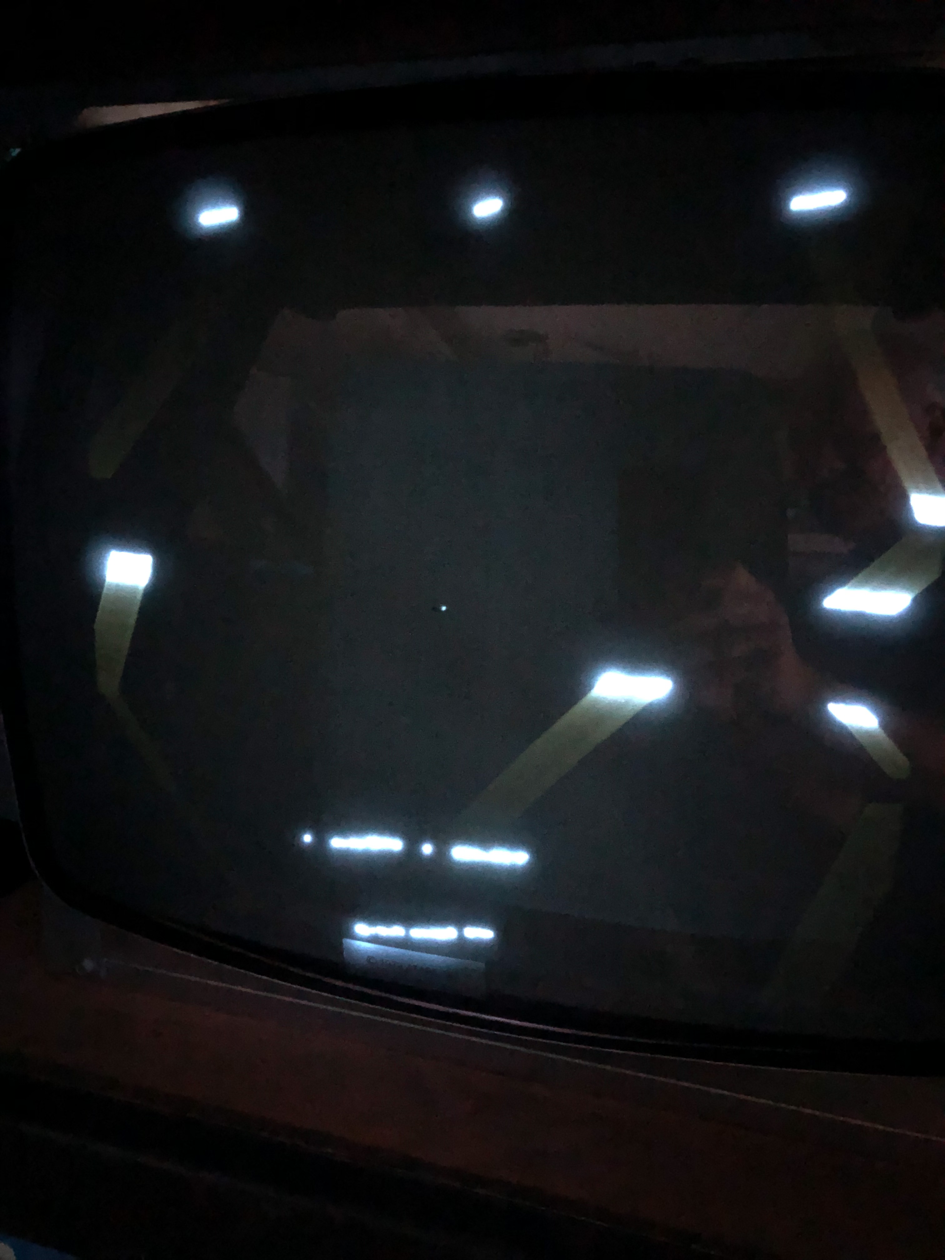
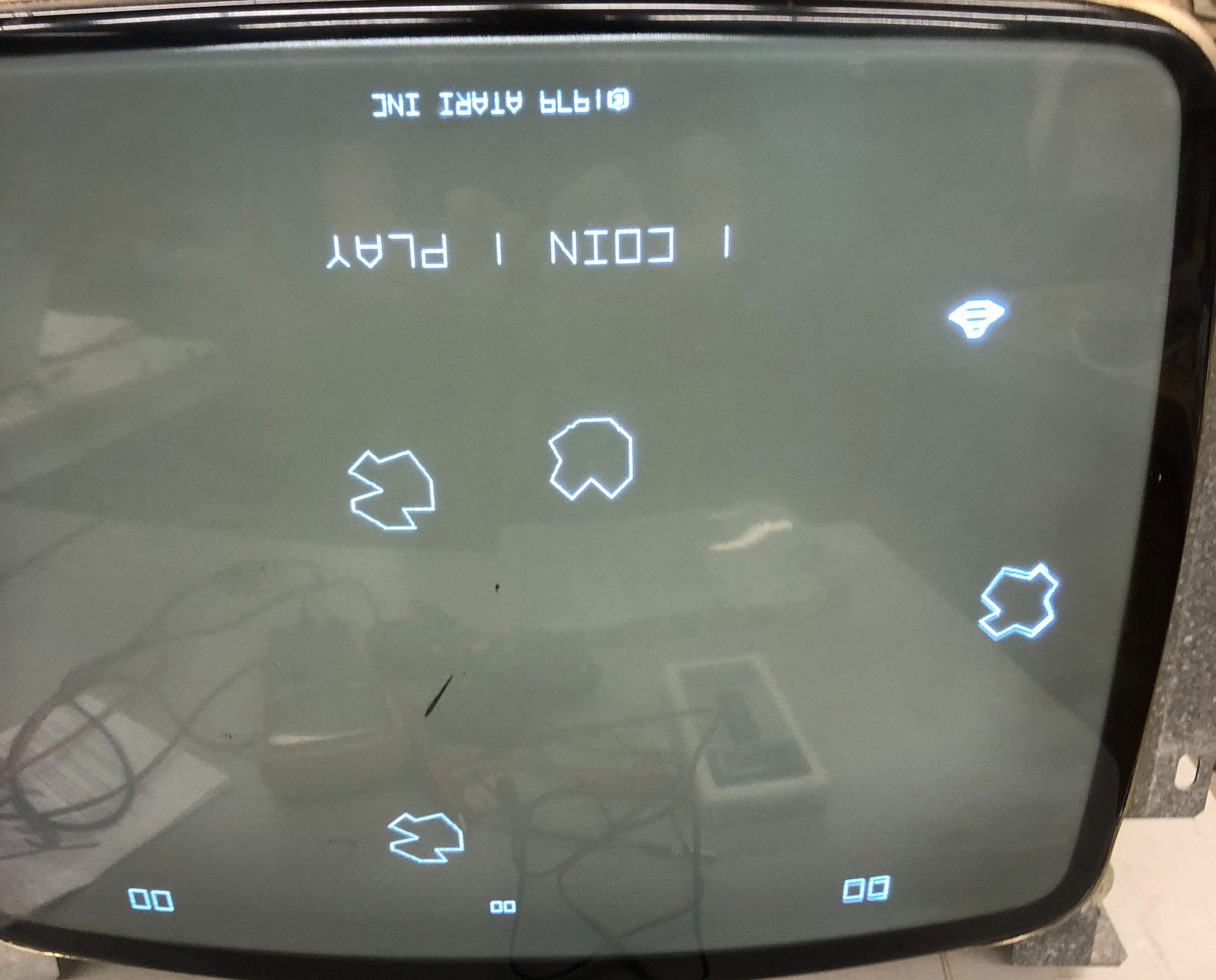
Putting the board into test presented this pattern. I poked around the board a bit and at first I thought I had seen bad signals from the 74LS109@A9. Replaced it, but no joy. At one other point I pulled the 273@F7 because the Timers were off as compared to a good board. But this was just a symptom, not the problem.
Running through vector generator tests, the HALT and VCENTER tests were running at the exact same timing. These commands in the DVG instruction set are before the vector timer circuit, so I did not suspect anything there. I looked all over the stack counters and addresses and all the chips appeared normal. I even delved into reading some 6502 Asteroids source code to look for a clue.
After a fair amount of head scratching it sort of hit me, the vector code was skipping the first instruction. I was able to prove this using the FPGA Catbox.
My first test was to run the test pattern from the Catbox as seen above. Next I duplicated the very first instruction – now there were 2 of them. The first one which I suspected it would skip and the second one to actually execute. I recompiled and executed it:

Perfect Asteroids grid. From there I tried all the other VG tests, duplicating the first instruction and they all ran correctly.
PROBLEM DEFINED! The VG was initializing to x4004 instead of x4000. But then executing the entire VG code correctly.
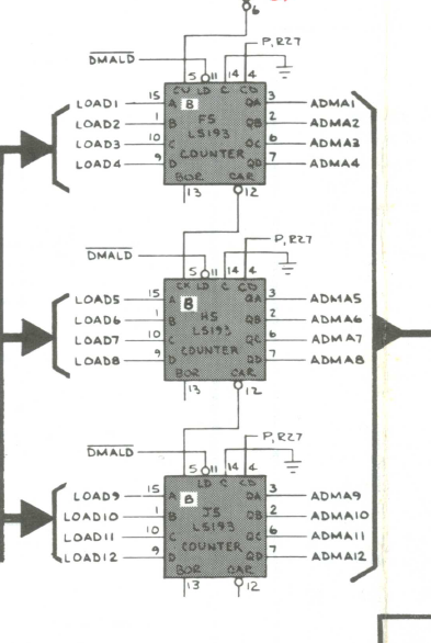
From there is was a bit of a learning experience. All the usual tricks were not working to find the troublemaker. Then I decided to set the Catbox to read x4000 and test all these address bits. Testing against a good board I could address x4000, x4001, x4002 and walk the bits up the address lines. The 193@F5 had already been replaced prior to me getting the board and H5, J5 were the same new chips. I replaced the LS157@F3 because it looked like it was the cause at first. However – The 193@F5 was a brand new bad chip, doing bad math. But only on the initial address load of zeros (it seems). Interestingly, piggybacking a good chip had no effect on the timings – however – piggybacking the bad chip on the good one after the fact messed it up..
The upside is I have a much better understanding of the Digital Vector Generator.
Board Works!
Board #12 – Board repair for a friend
This board started as “let’s see if we can work on it over video and text” with a friend who wanted to see if we could do it remotely. Remote repairs are very challenging. He has a digital scope, but no analog scope at the time we started it.
He was able to set it up on the bench and it was watchdogging. Not the best place to start. We poked around a bit and found a dead address line on LS244@B2. He didn’t have one, but scavenged one from another dead board and it booted! That’s good news.

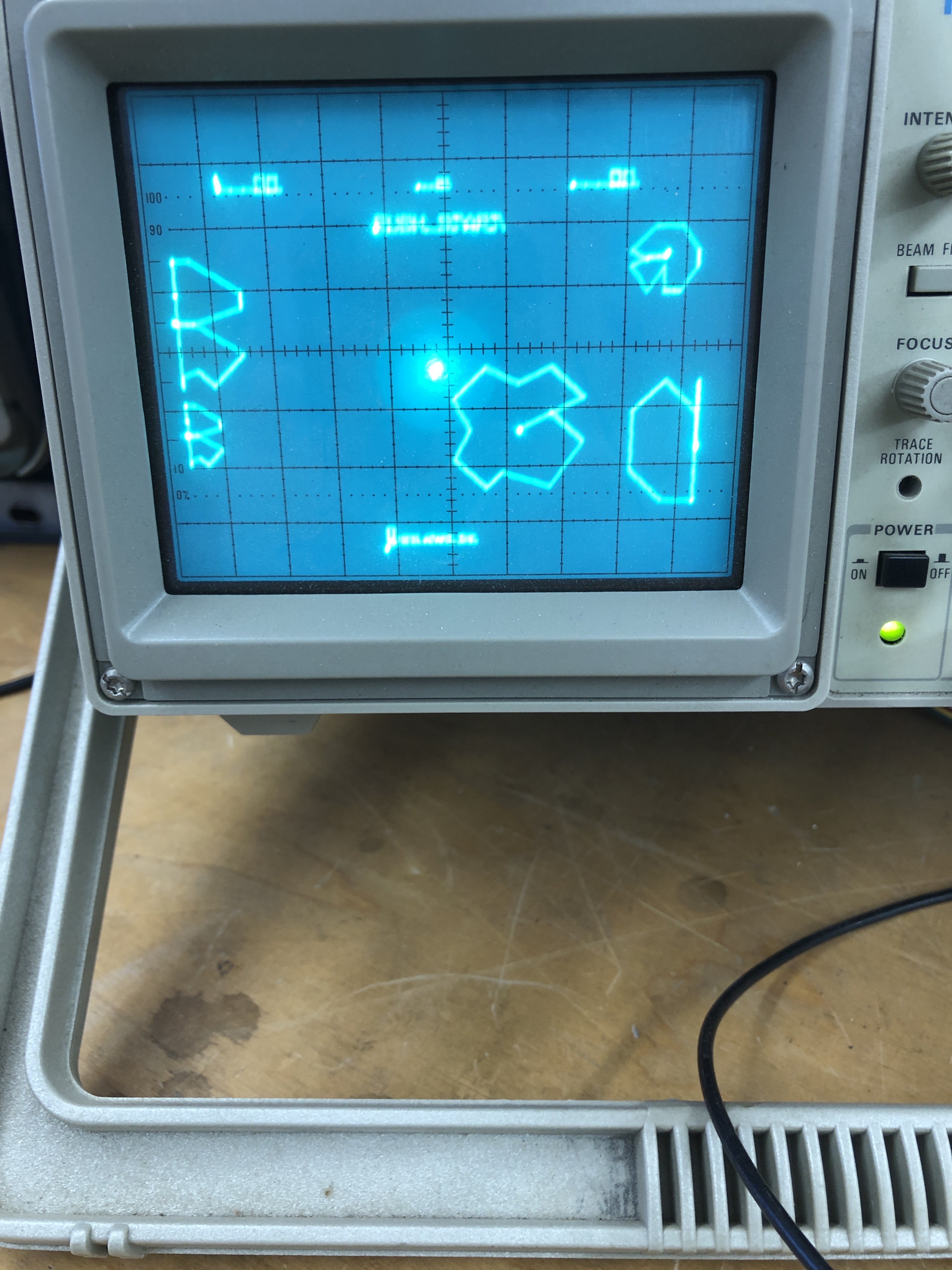
From there we got this. Not a bad start from 1500 miles away. Squiggly lines are usually stuff in the analog section. At the time we tried to diagnose with the digital scope as much as we could. But there was a bit of shotgunning that happened because of limited tools. We went back and forth over a few days but a low cost analog scope popped up ($80) The order of how we found stuff is a little fuzzy – there definitely was a bad analog switch and we got rid of some of the squiggly lines. DACs and TL082’s were swapped around, etc.
We got to a point where I kept seeing flat asteroids moving around and gave some homework to compare X and Y counters. I knew there was a bad Y one in there. He ordered some 191’s and we set it aside a few days. Then this happened:

Fixed the flat asteroids, but still some issues. At this point my buddy was done ‘learning’ and shipped me the board. But we got a lot repaired remotely.
Once I got the board…
The barber pole was caused by a broken trace under the X DAC socket. Pin 11. On the scope you can see the Atari logo at the bottom of the screen trailing off up and to the right. It was caused by LS161@D7 in the vector timer.
Board works!
Board #13 – Board in for repair
No description given on this one, it came in as part of 7 sets of different boards sent in for repair.
First up was replacing a lumpy repair job on burned up edge connector. The mask ROM@F1 was bad, replaced it. From there all RAM, ROM checked correctly. I then spent too much time messing with the vector generator tests.
The board ran HALT and CENTER correctly and I was able to determine JMP was running and the program counter worked fine. It seemed like the vector timer was broken since only the commands that did the drawing were not working. The upside is I figured out how to use signature analysis on the Asteroids board and used this Asteroids Signature Analysis Guide. But the guide wasn’t very helpful inside the STATE machine. In the past I’ve had the VG run HALT and CENTER and a bad chip was the root cause of bad vector timeouts. Not this time. Finally I decided to pop out the state PROM@C8 and swap one in. The state machine is now fully working.. Now I know..
From there the vector output was messed up. Clipping to the TL082’s @C12,A12 Pin 7 – the image was clean.
Moving to the TL081’s@PIN6

Got me this blurred image.
Replaced the TL081@B/C12 first – it was not the issue. The analog switch@B12 was the cause. I then had an issue where the image was upside down and flipping caused the screen to turn in to a line. Replaced the matching 4016@D12 to get the display working.
Another issue was no THRUST sound. Another analog switch, same date code 4016@R11 was the fix. The board is showing some random vector glitches. I’m running it to see if I can burn out the offending chip.
The glitch took a while to hunt down and I try to find the issue vs. shot gunning chips..
The two small asteroids cross and there is a vector glitch between them. Turns out I was lucky to see them. The Z axis was on long enough for the beam to stay visible. On the scope, there were little vertical lines that blipped onto the screen. Sometimes there was a pattern, sometimes not. The only real pattern was it seemed to happen on the bottom 20% of the screen, never above the center. I ran the board for a few days hoping to kill the chip, no luck. When it was consistent – I tried looking for a digital cause, but nothing was jumping out.

I’d replaced the 4016B@B12 earlier – flipping the screen showed distorted characters. It was correct before.. I replaced it again and then thought, maybe the TL082@A12 was the issue – spiking a small negative voltage now and then causing the quick flash vertical line. That was it. Problem solved. Makes perfect sense now.. It appeared as a random vector being loaded and then fixed on the next screen draw..
Board works!
Board #14 – Board in for repair

Board was pretty dirty, but cleaned up nice aver washing. Very little prior work. It did have this speedup hack that the owner asked to be removed.
Board had 2 bad RAM @N4, @P4. Once up and running – the shipfire sound was barely a beep. Replaced analog switch @M9 to restore proper fire sound. Somewhere along the way during burn in testing, the power LED died. Replaced it too.
Board works!
Board #15 – Board in for repair
Reported issue: board locked up, solid LEDs
Connected to the CATBOX, ROM & RAM tested fine. Vector Generator was non-functional.
Probed around and determined it was actually stuck in RESET. The interesting part was that HALT on the LS109@A9 was toggling, but HALT was not.
After seeing PIN11 bein held low – traced it back to LS08@E6 Pin8 was floating.

Replaced LS08 and the game booted and ran, great!
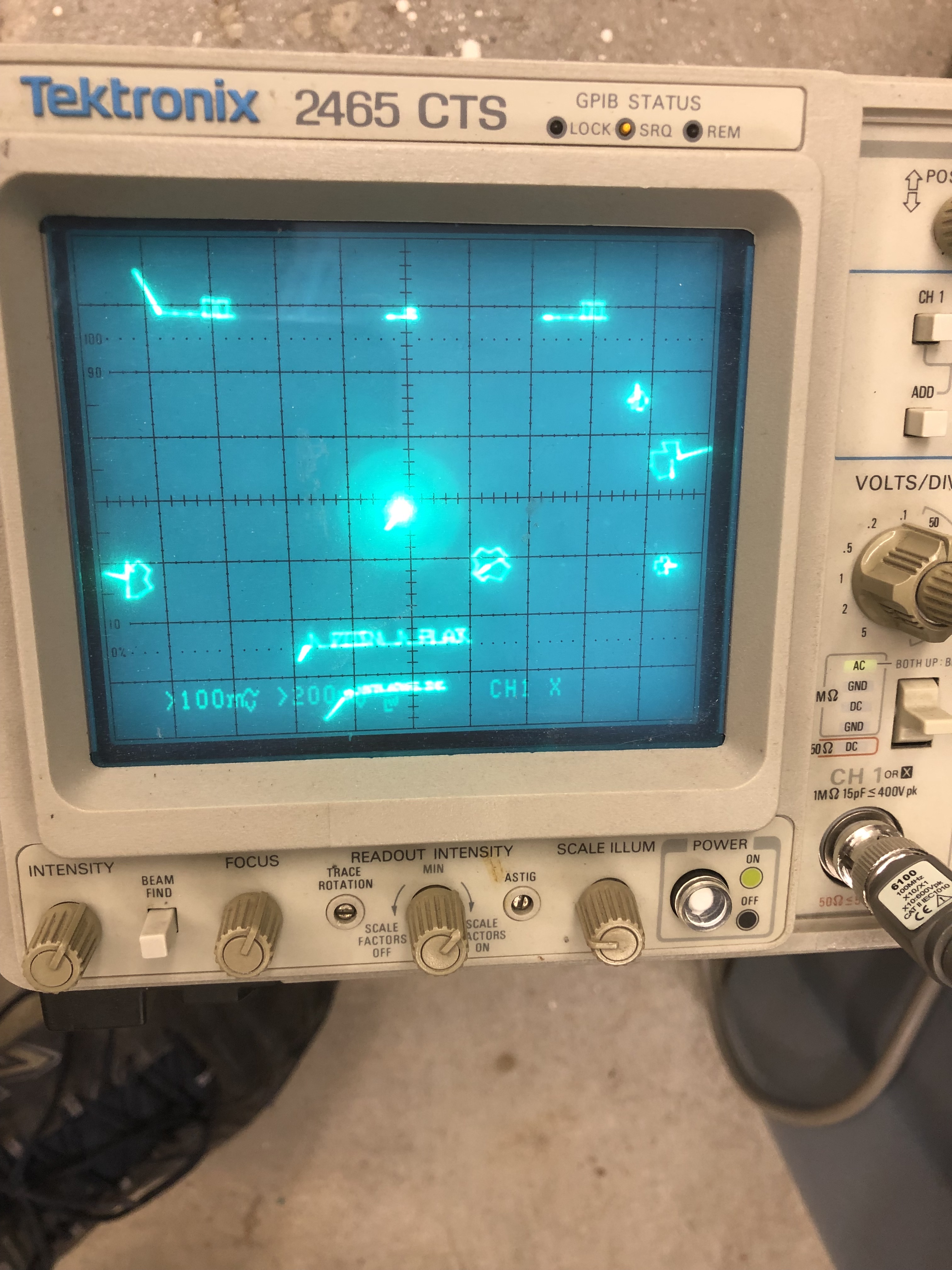
During testing – the saucer sound was more like a slow ambulance than a saucer. Probed around the saucer sound circuit looking for issues, but it all seemed normal. just slow. Since the 555 timer controlled the sound, I checked the capacitor C45 connected to the 555 timer. It was originally a 10uF tantalum, but had been replaced at some point. The cap said 10uF, the meter says something else..

It tested way off in circuit, I lifted a leg and checked again – wow! I’ve never had a cap fail like this. off by 130%. Replace the cap and the saucers sound like saucers again!
Ran first 12 hour burn in session and the board locked up..
This next part spanned a couple of weeks – testing an Asteroids 5 seconds at a time!
It took a while just to narrow down the symptoms and define the problem. Power on the board and it would be stuck in reset or watchdog for 3-5 seconds, then beep a few times, then the board would run, however it would not run over night. Sometimes it would reboot and others it would be frozen.
How do you figure out what’s causing a reset inside of 5(ish) seconds? I tried a bunch of things and didn’t take super detailed notes and some of these are out of order.. but here are the highlights.
- Determined that the watchdogging was on the CPU side (pulled LS42@L6 Pin1)
- Good – it’s not in the vector section
- Swapped in a different set of ROM/CPU – No change
- Socketed CPU RAM/swapped – No change
- Replaced the sockets – they were the gold pincher ones – No change
- Used freeze spray to see if I could find the offending chip – Didn’t locate it
- Heated chips with the heat gun (that I use for heat shrink tubing) – Didn’t locate it
- Piggy backed any chips involved in the core part of the boot process – no glitches..
- Did a lot of testing with the watchdog disabled and enabled to see if I could find missing signals that popped in.. couldn’t see anything.
- Tested in game mode and diag mode.
- It failed in DIAG mode and the circuits were in steady state – so things were easier to watch in DIAG mode
- I chased the 3kHZ signal around a bit because during the watchdogging it’s voltage would bounce up on the scope – but it wasn’t really part of the problem.
- Pulled the LS251@L10 since it had the 3kHZ and TEST – Not involved.
- Since the original problem was in the watchdog area, I replaced a few chips in that circuit. LS393@B4, LS74@D4, LS00@C6 – No change..
- The biggest problem was testing 5 seconds at a time
I picked up the Slice Tool recently and I’m still trying to figure it out.. But it did help me find the chip causing the watchdog issues. Learning Slice was part of my test a chip, wait a while, test a chip, wait a while routine..
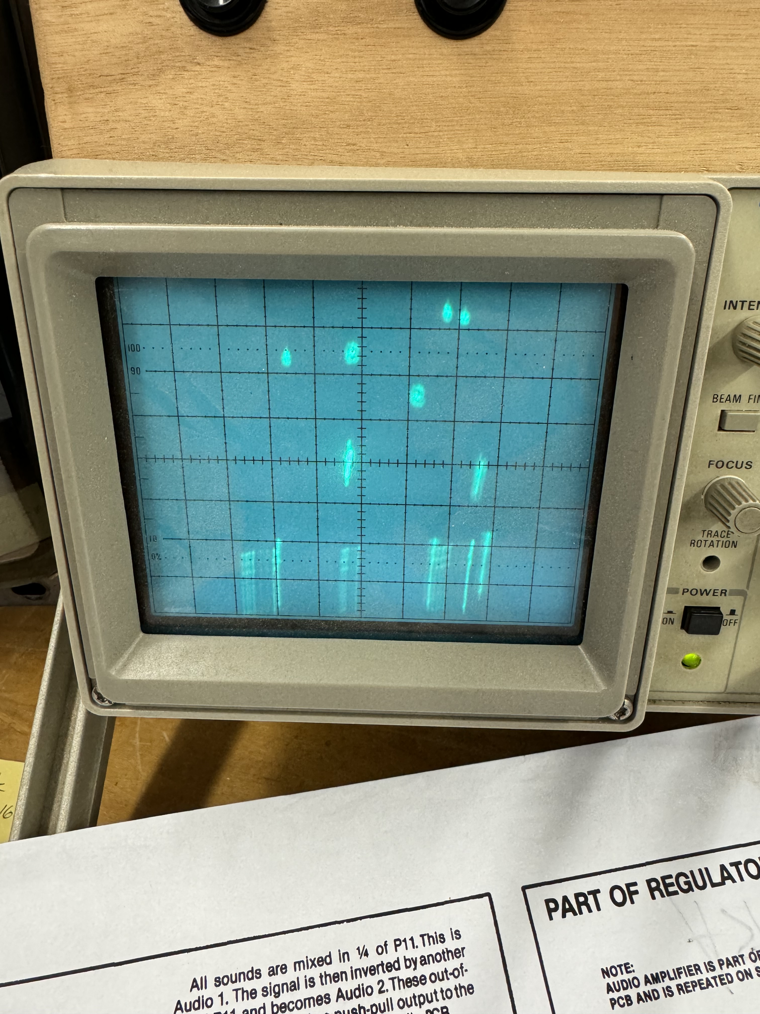
After many before it, I tried the LS02@D6….
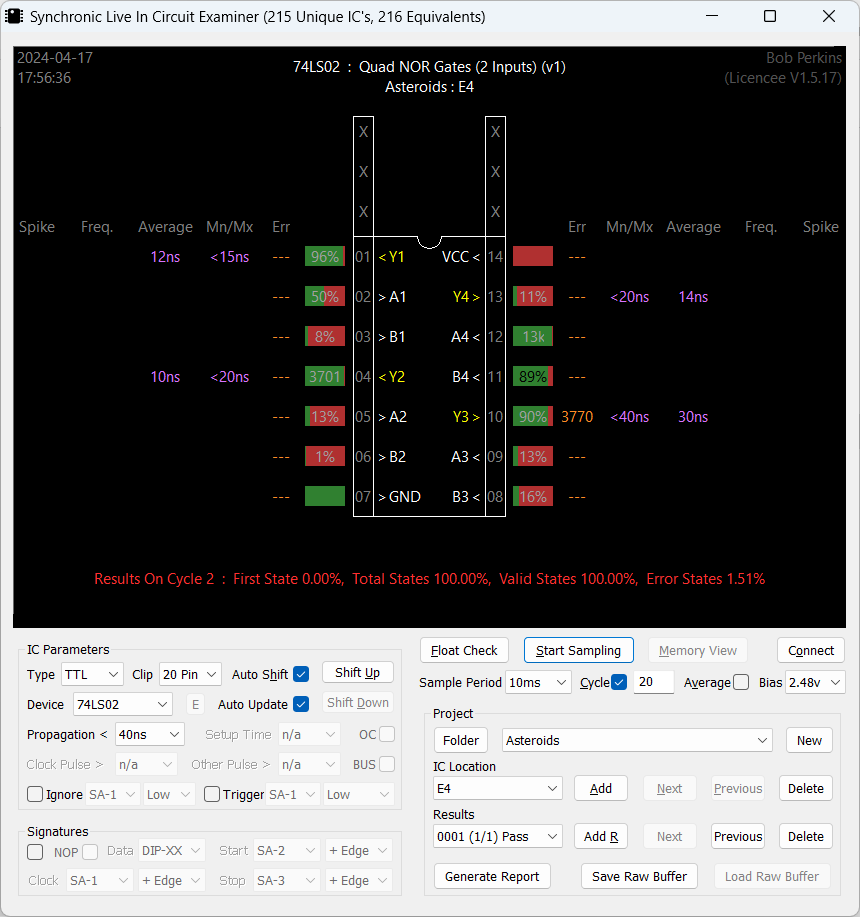
The breakthrough moment was while cold, I needed to adjust to a 65ns propagation setting before it would start the test. If I started at 40ns – you get all of the red errors above and PIN10 shows 3770 errors. On a good board, I could start at 40ns propagation and test cleanly.
Sitting on this chip at 40ns and waiting for it to ‘warm up’, The board started running after ~5 seconds of power and propagation speed dropped below 50ns. The LS02 eventually ‘speed up’ further and passed at 40ns and tested correctly.
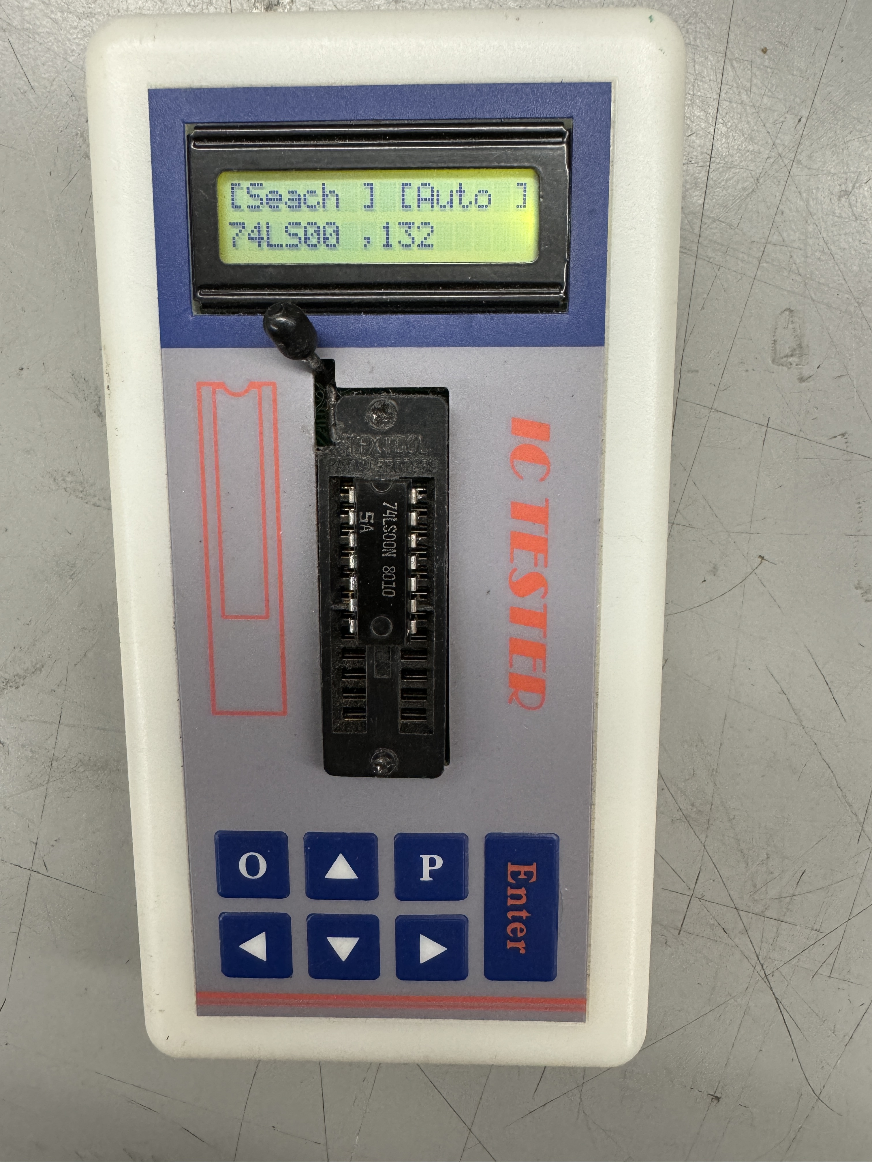
Pulled the chip and it fails in the tester! LS02@D6 – it was just a little old and slow it seems. As another test, I tried hitting the ‘Enter’ button on the cheap chip tester for a few minutes to see if it was pushing enough voltage/current through the LS02 to make it pass.. it didn’t. The Slice documentation stated that on most TTLs, if the propagation was above 40ns, start looking at replacing the chip. It was right!
There is ‘technically’ still a glitch in the board. When powering on cold and only in DIAG mode, the game will watchdog once (and only once) and then start. Even this only happens very rarely. Once the board warms up it goes directly in to DIAG mode w/o a reset.
In game mode, it boots directly as it should. I’m not searching for a failure that happens in .25 second increments 🙂 I am running an automated test cycle (10 min on, 10 min off – 60 cycles) to see if maybe the weakling will die.. If it doesn’t.. We’re good.
Board made it through 3 days of test cycles without issues..
Board works!
Board #16 – Board in for repair
Friend sent me his Asteroids board. Had an interesting failure..
The Asteroids roll off the screen on the right and stretch back to the left side. At first it looked like an analog section issue. I replaced the 7915 and 7815 voltage regulators just to be sure. They were original and I’ve seen weird issues with them in the past. It was low probability and not the issue.
Once I paid a little closer attention – it was clear that the issue was very specific to the vector moving off the screen and it was some sort of carry over issue.

Thank you Atari for the excellent detail, saved me a little time looking for the carry over issue..

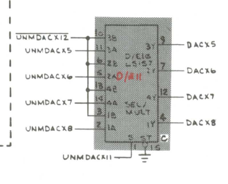
In this specific case, the 74191@C9 (not an LS191 on this particular board) had a grounded/shorted output on PIN6-UNMDACX11. Interestingly the carryover bit on PIN7 was working just fine..
Replaced with a 74LS191@C9.
Board works!
Board #17 – A board from my collection
I’ve had a number of Asteroids on the bench recently – so I decided to fix one of mine.
After cleanup – plugged the board in – no clock. Noticed – no crystal! Should be simple right? No – still no clock. After messing with it a bit..
Turned out LS04@B5 was bad.. Replaced – clock restored! It was still a bit intermittent operationally. Had the gold pincher sockets that were not very tight. Replaced all the sockets.
Board works!
Board #18 – Board in for repair
Placeholder – Started this one and shelved it for now.
Board #19 – Board in for repair
Board was originally reported to be resetting, but then went dead.
Connecting to the test equipment showed RAM and ROM were good, but the vector generator was stone dead. Probing around the circuit with the CATBOX running was not useful at all as it turns out. I saw that DMAGO was running as expected, but the vast majority of the STATE MACHINE was doing nothing. I changed tactics and disconnected the CATBOX.

With the board running and watchdogging, I could watch all of the inputs and outputs of the STATE MACHINE and determine if the chips were doing anything at all. Working though all of the inputs and outputs – I came across the LS10@A8 – it had 3 input signals but seemed to have no output signal. Poor mans comparator – I piggybacked an LS10 with leg 6 lifted – there was my output.
Replaced it and the vector generator sprang to life and everything was running. Put the CATBOX back on and saw all of the vector tests were working as expected. Except the board was still watchdogging.
Checking the watchdog circuit..

I could see WDCLR coming into the LS00@C6 and an output which seemed acceptable. I followed it all the way through however the RESET was still being triggered. Piggybacked the LS00@C6 – problem solved.
Chip tests good – just not at game speed.
Board works!
Board #20 – Board in for repair
This one I got in as a favor to a repair person who had started working on it but had to work on different projects.
Reported issue was very unique – game ran perfectly but would not accept coins. This one was tricky for a while.
It came to me missing the 566@P10 – creates saucer sound, the CPU was missing and I did not notice at first, one of the legs of the 4016B@R11 was outside of the socket. This turned out to be significant because it generates the new life sound during the game, but it is also the SLAM switch sound.
I connected the board to the CATBOX – and updated my config file so that I could see all of the COIN presses in the user interface, followed signals, etc. All the hardware worked. My test harness for Asteroids needs a new connector so it also contributed a little to my confusion. I decided this was a software issue but different EPROMS didn’t make a difference.
Luckily – Asteroids may be one of the most documented games ever made 😉

I decided to take a look at the coin routines and there it was staring at me.. SLAM switch. If the SLAM switch is activated, the game will not accept a coin. Keeps those coin door kickers at arms length! I had been checking all through the input area already.

But not the SLAM switch. Pin13 LS251@L10 was either floating or being dragged down. Before doing anything I tested my theory – I used a probe and pulled up Pin13 with 5v+ and easily coined up a game – finally.
This chip was socketed. I removed the socket, cleaned up the area and put a new one in. Rechecked and it still coined up, but the voltage was only at ~2.5-3V. All the others were at 5v with the pullup resistors. A little more checking and I determined C72 was bad and dragging the voltage down. Replaced C72 and back to a full 5V+.
I realized I still wasn’t getting a new life sound. I didn’t have any NE566’s – so I borrowed one from another board. No life sound or SLAM. This is where I found the leg out of the socket@R11. SLAM and life sound restored. I’m guessing the other repair person was getting the SLAM noise and focused on the COIN issue first? Fixing the SLAM would have fixed the COIN as it turns out.
Board works!
Board #21 – Board in for repair
This one I got in as a favor to a repair person who had started working on it but had to work on different projects. Came with the prior board.
I did a full maintenance and check on this board and it worked 100%, except.. as part of my repair checklist. I noticed it was not triggering the coin counter. I’m sure no one ‘really’ cares. But I check it.

To start – all 3 2N6044 transistors showed an E-C short. Not likely, but I pulled one and it was fine out of circuit. Next I switched the DIP switches to OFF since their job is to tie all 3 outputs to a single counter. That showed Q11 with an E-C short. Pulled it – no problem. The only thing left was C115 – it was shorted. Replaced it and all coin counters work as expected.
Board works!
Board #22 – Board in for repair
Board sent in reported graphics issues and a burned up edge connector.
I started with the chip and board inspection and cleanup.
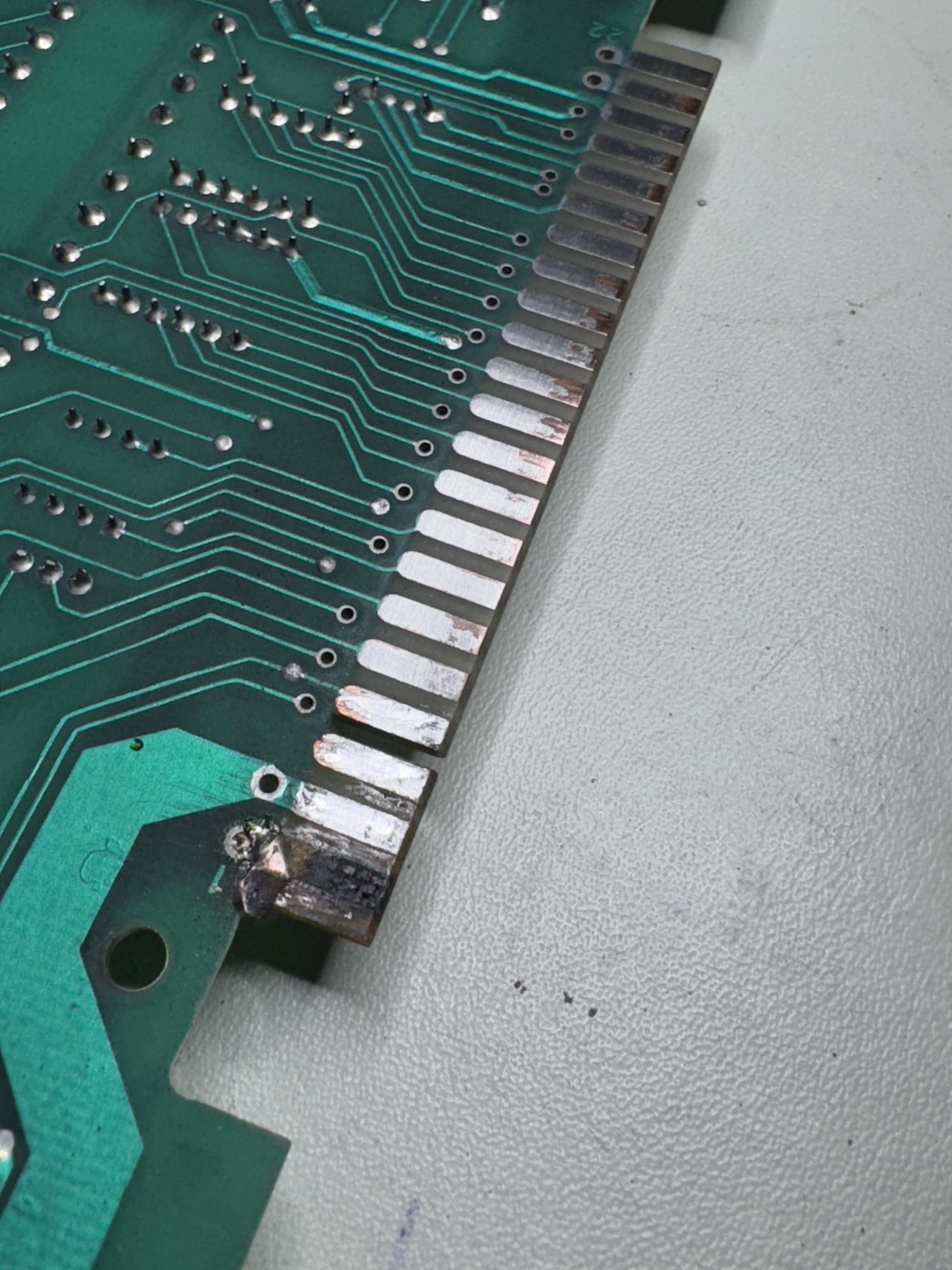

These were in pretty bad shape. I cut off the loose metal, clean up the area with acetone, fill the divot and fiberglass area with UV Resin and sand it down flush with the existing board. This finger wraps around which makes the copper tape repair easier.

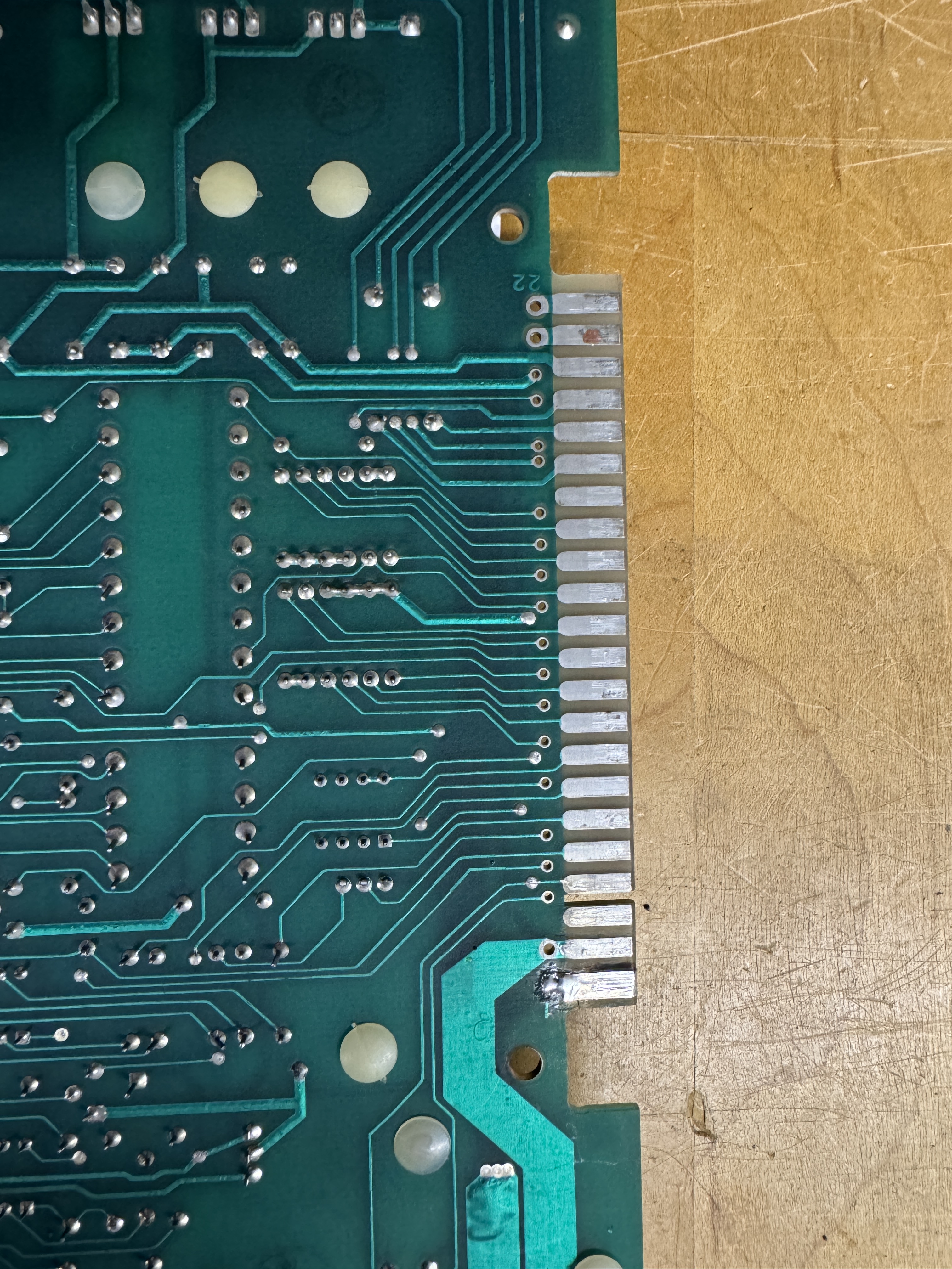
Clean it up again with acetone and then use liquid tin to coat all of the exposed copper. Helps prevent oxidation. Edge connector repaired!
Once I could power up the board I verified RAM, ROM. The vector generator was not working correctly. Most of the tests were running – but addressing tests were broken. The JMP and JSR instructions were not working. Spent some time testing in the program counter section, everything seemed to be running there. I backed up to the next layer and checked

Working through these guys, I found that LS273@H7 – Pin 3 was floating. This was a previously socketed chip. Beeping out the connections – the pin was not connected to the trace.. removing the socket and pins…

Pin 3, 5, 11, 18 were in pretty bad shape at the board level. The remaining ones were electrically connected. When half of the ring around the via is missing – I add Kynar wire.


Here are Kynar traces added to the top and down the via. Second pic shows drops of UV cured resin to lock them in place. If you don’t, the heat from soldering usually will break them lose. Socket and chip reinstalled. Barely visible repair with no jumper wires on the back.
Once this was completed – board was up and running. Played a game.. no thump thump sound

Some probing showed the 555 timer@N8 was bad. Replaced.
Board works!
Board #23 – Board in for repair
Board sent in with graphics glitching..

What I saw was what appeared to be a 1 bit (or so) as a zigzag line in the test screen. I initially looked at the analog section but nothing was initially jumping out at me. The other tricky part was the distortion was too small to really zoom into on the scope to help with diagnosis.
Here is a situation where using the little known DIAGSTEP feature. On Asteroids it draws a diagonal line across the screen. When looking around the circuit it exercises the X and Y pretty evenly and there is a lot less ‘noise’ in the circuit.


I grounded out L4 side of R90. Do this while in TEST mode and you get a diagonal line. From here I looked at the analog section working backwards with the scope.
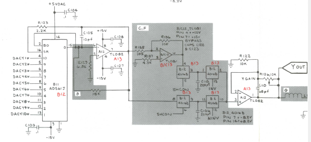
The signals on the TL082@C12 Pin 1 and 7 looked normal as well as the ones on the X side. I worked backwards and it appeared that he input to DAC@B11 Pin 6 (DACY3*) was missing (no pulse) So maybe the zigzag is a 3 bit error? Working backwards again…

I checked the output of 74LS374@B10 – Pin 16 matched – no output. Checked the input @Pin17 No input. Back one more chip.. 74LS157@A10 Pin 12 No output signal.. Checked Pin14 – it had an input signal. Replaced LS157@A10. Graphics fixed!
Board works!
Board #24 – Board in for repair
Powered board on and game appeared as just dots on the scope. Asteroids and ships moving around as dots essentially. All RAM and ROM tested good and the vector generator also tested good. When that happens the issue is often in the analog section (but not always).
A quick look at the analog section showed it was doing what it was told and there was a digital issue. The vector generator working means that a lot of vector sections are working.. Looking at the XY position counter section I determined there were wasn’t X orY rate clock going into the counters. Makes perfect sense and explains dots moving around the screen.

This particular Asteroids was the -06 revision.

The -06 revision is loaded with 4 – 82S131 PROMs that calculate the X and Y rate. I’ve bumped into this board revision once before and the E8 PROM was the issue. Checking the PROM@E8 I saw ‘some’ inputs and no outputs. I removed and checked it and it read good. After socketing and reinstalling I got horizontal lines on the screen (this is a problem.. read on…)
At this point I was able to determine that PROM @F8 was the bad one, I pulled and tested it. Read all FF’s in the reader.. I made a temporary ROM using an adapter.. Now my horizontal lines had some Y axis, but things were still messed up. In the diag screen I was now getting this..
After messing with it for a little while, I found the issue. Replacing the PROM@E8 and getting a different result – tiny hair of solder jumped to a trace and caused the X output.. Self inflicted wound here.. Once I cleared that the actual offender was the PROM@F8.
Board also needed a CPU socket.
Board works!
Board #25 – Board in for repair
Connected board and it was watchdogging.
Checked RAM and ROM – all good. Checked vector generator – had HALT but no CENTER.

Looking at the program counters – there was no clock getting into them – so of course the vector code could not execute.
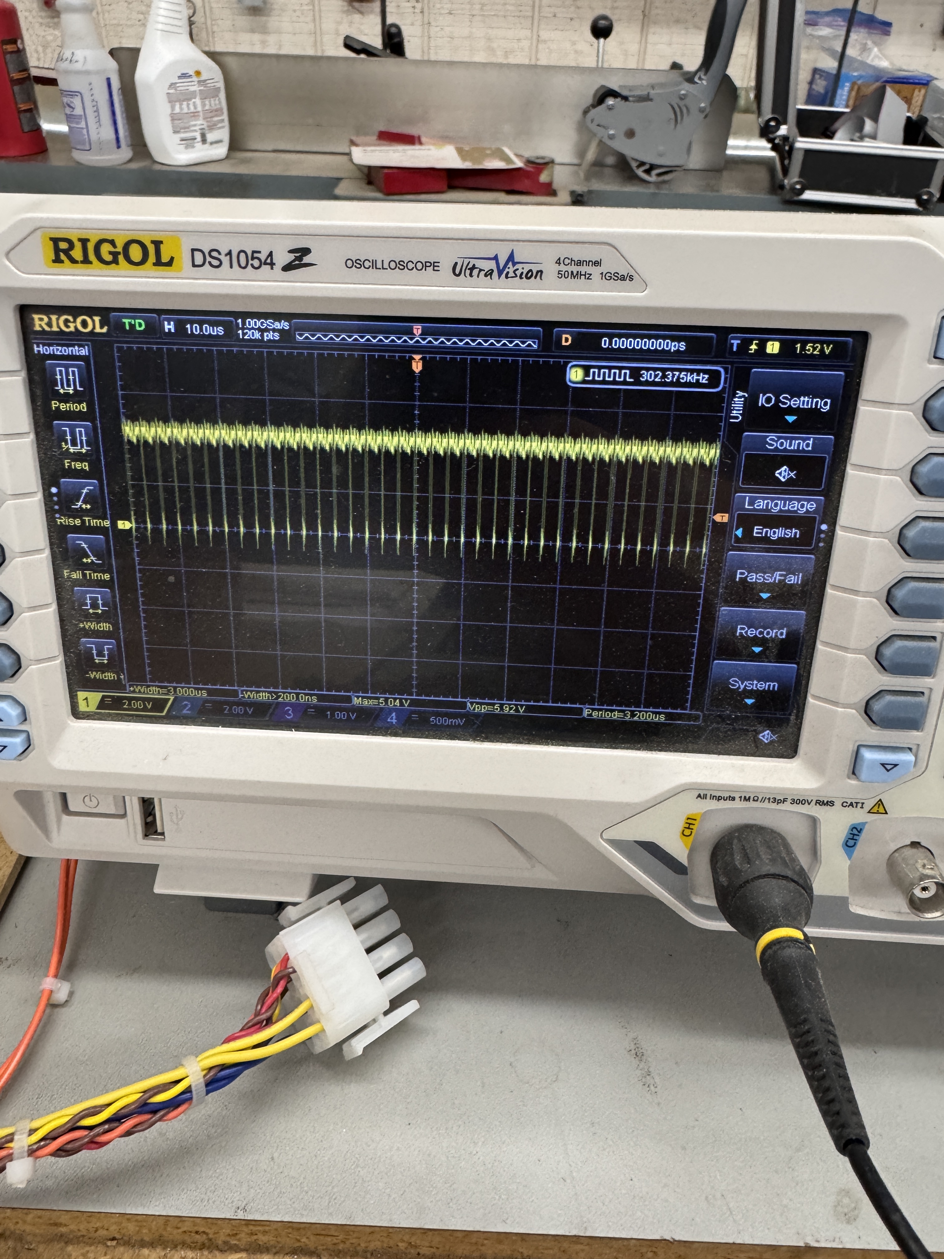
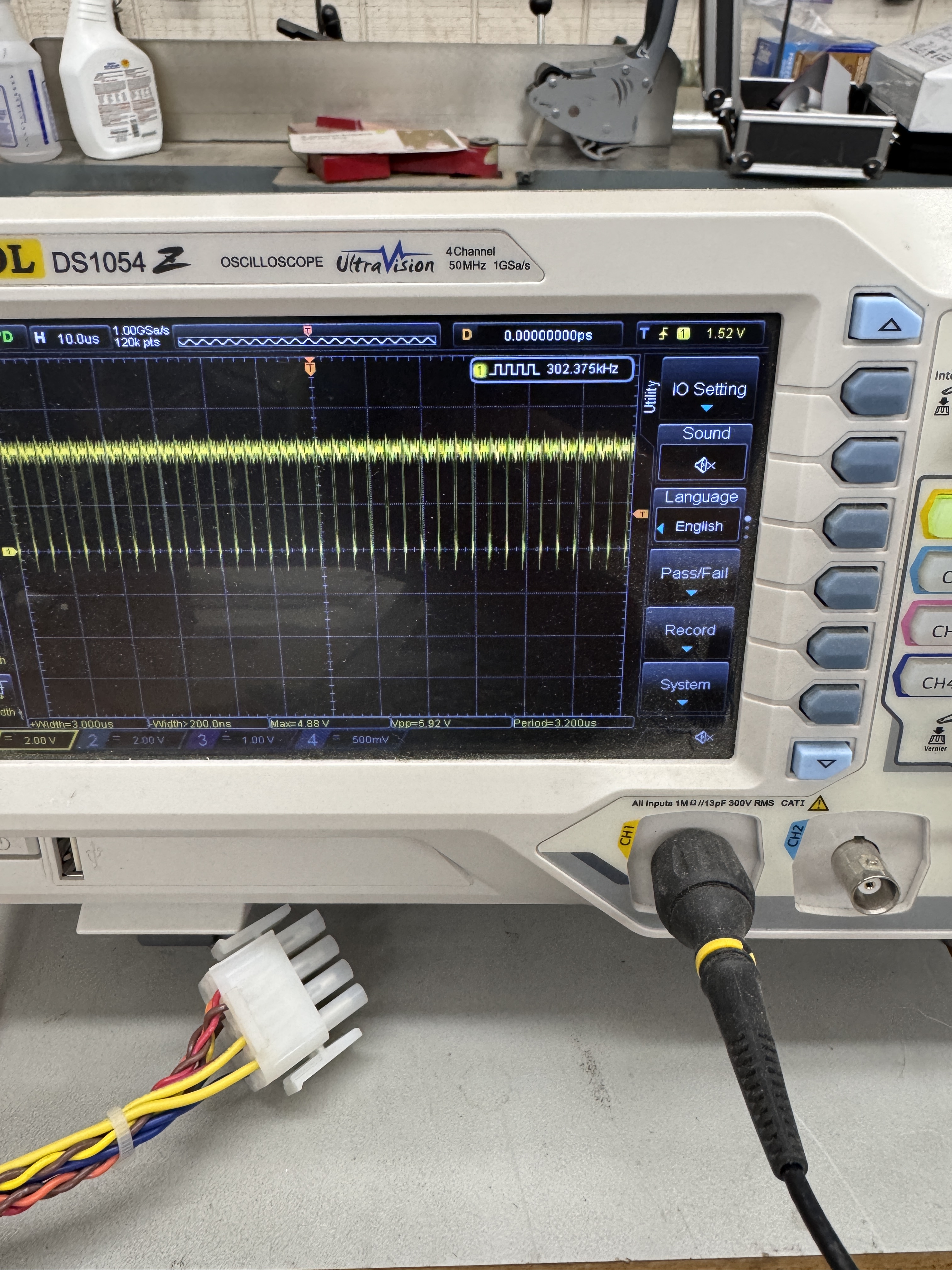

Looking at 74LS08@B9 – in order… Pin 4 input.. Pin 5 input… Pin 6 output. Pin 6 never gets down to 0 volts. Here is why I prefer the scope to the logic probe. A logic probe would likely show this as toggling and you would move on to something else… Replaced LS08@B9
Board works!
Board #26 – Board in for repair from a friend
Board was not running. Turned out to be just the CPU socket – old Atari pincher socket. Been solid once replaced.
Board #27 – Board in for repair
As with every board – they get chip legs cleaned and a close visual inspection. Stand up pots to be replaced.
This one had an interesting failure – game played – but the vectors were a mess.
Working back from the analog section.. On DACX7* signal @D12 – Pin 10 was stuck high.. Tracing backwards – It is fed from 74LS374@D11 – but Pin 5 and Pin 4 were high.. Backwards again..
It was being fed from 74LS157@D/E11 – this chips was bad and it was replaced. It didn’t fix the issue – it just changed it. Bad data was now being fed to this from 74LS191@D10.
Replacing the counter corrected what looked to be analog issues. Board also had a bad ROM #143@J2. Burned a new one.
Board works!
Board #28 – Board in for repair
Board got standard maintenance and inspection. Had an interesting failure that required some time to correct. Power the board up and it failed.. Unless you waited a minute or two and then it corrected itself.
Testing revealed a bad RAM@P4 – Bit 5 was bad.. until it was good. Did full cycle testing and replaced upright pots.
Board works!
Board #29 – Board in for repair
Reported symptoms were graphics glitches.
My first thoughts were this was a memory issue or maybe a vector ROM. Also it was the type of failure that seemed very borderline and I’ve had success piggybacking chips trying to find a glitch that corrects it enough to provide direction.. Piggybacking as a search method did not help in this case.
Another symptom was this issue also seemed to correct itself after 30 seconds when cold. If I power cycled quickly, it always happened. It just correct itself faster.. This was not a thermal failure.
Two of the vector RAM had already been socketed and replaced at some point. I removed and socketed the remaining two – no joy. I also replaced the socket for the vector ROM, no change. I did a power cycle automation (10 min on/10 min off) and let it run over night.. no change.. The partially failing chip did not fail any further.
So.. normal tricks not working..
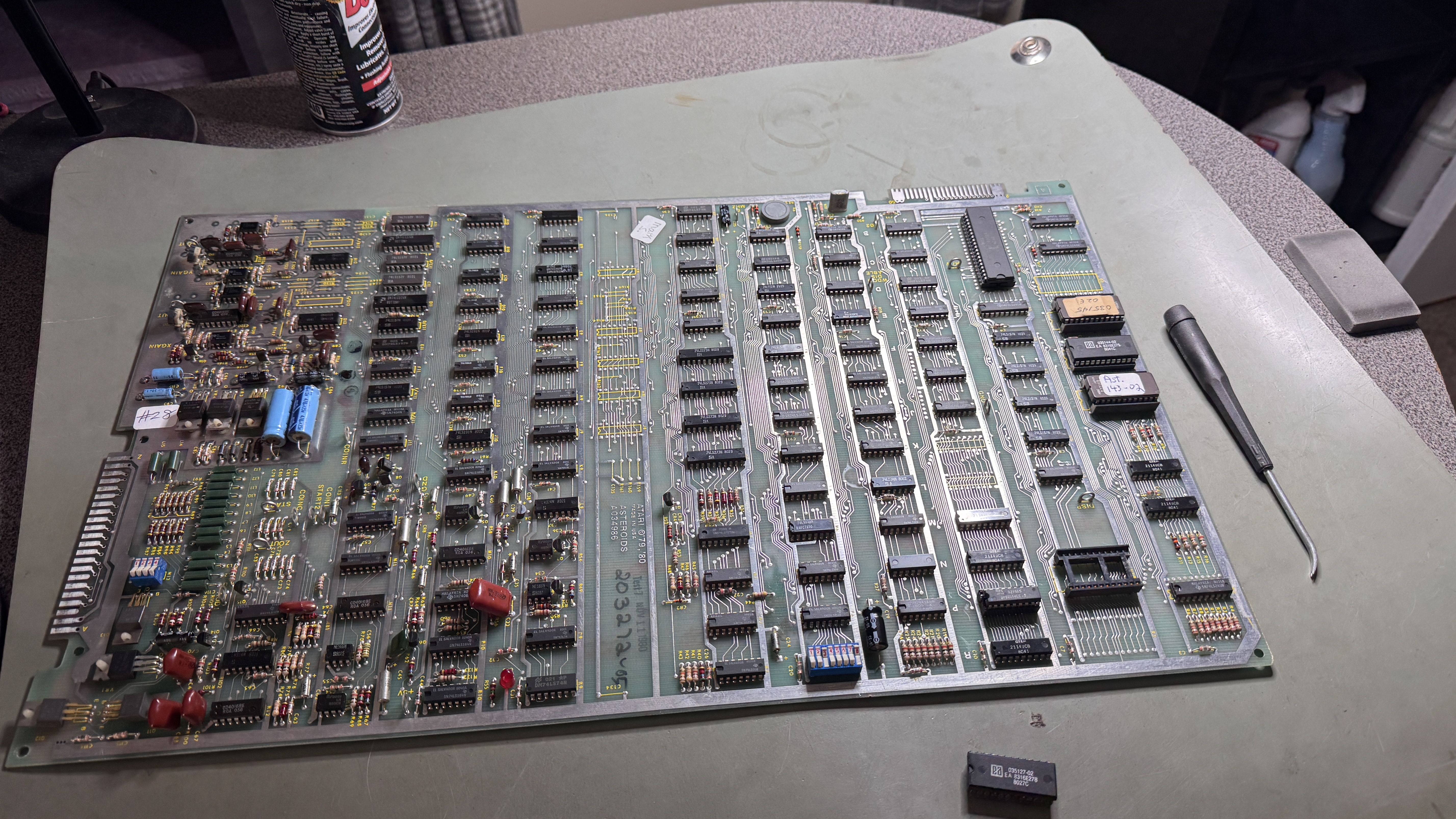
I went over the address selectors a number of times and everything looked like it was working. Using the Slice tool I wasn’t seeing any failures. Checked the supporting counters coming into these.. nothing jumping out..
Then I remembered the pullup/pulldown resistor clip that I have and tried that – I was finally able to toggle the graphics glitches with the press of a button – all inside of 30 second windows.. So the diagnosis process was actually spread over a couple of days. From here I probed each pin with the scope and touching the probe to /VMEM also corrected the glitching.. I had not seen this before..
I replaced the LS157 that responded to the scope probing the best.. and it corrected the issue.. a little. I did this two more times and the overall glitches got better.. But clearly I was masking the problem – not correcting it.
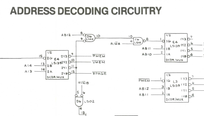
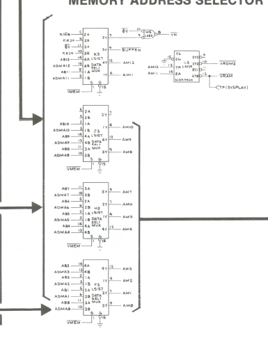
Tracing backwards, /VMEM comes out of the 74LS139@E4. This had been socketed and replaced at some point. The chip was a Texas Instruments (good) – but the socket was junky. I replaced it. No difference..
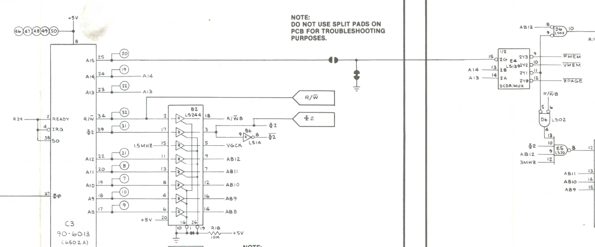
Going backwards a little further.. The /VMEM signal is actually generated by CPU Address lines A13, A14.. These are direct connections to the LS139 without a driver chip..
Could it be that simple?
Yup – replaced the 6502.. Problem solved. I forgot to get a pic of the chip, but it was not a standard looking CPU. Also interesting is I had some Rockwell 6502’s and they presented the same issue. Lesson learned.. CPU can work 100% and still not be able to directly drive other chips it seems.
I did check the outputs on the scope and they both were showing the same voltage as the driven address lines. Maybe the propagation time is a bit slow?
Board works!
