
**** This is one of my oldest repair logs. Newest repairs at the bottom. The first ones were many years ago ****
Log of Centipede boards repaired to date:
My first attempt at repairing a PCB is how I determined my approach to triage and setting a baseline for repair. After watching hours of videos with different people and different techniques – I’ve seen three types in general:
- Guys who just start replacing parts without much diagnosing
- Guys who probe through the board and fix them with reasonable success rates
- Guys who break out a Fluke and Oscilloscope as their first step and map everything along the way.
There are merits to each of these – For the moment – using a logic probe is going to be the best way to figure out how boards work in general and once I’ve strained it to the point where its not enough – I’ll think oscilloscope..
This is some of my earliest repair work here at the beginning. I’ve come a long way since then… Centipede is the board I recommend for anyone who wants to learn PCB repair. It has a relatively simple architecture and they are inexpensive to acquire.
Board Zero – The Origin Story:
Board Zero was the board that came in the Centipede machine I’ve been restoring.
Triage:
Board played
- Sound issue where it cut in/out at weird times
- No high score retention
- +15v missing
- -30v missing
This board repair was covered here: Working on the electronics..
- Replaced 7815 voltage regulator for +15v
- Replaced 555 timer which fixed the -30v
- Replaced 7905 voltage regulator on the ARII board
Board works!
Board #1
Purchased off KLOV as a spare and training board
Triage:
- Missing Pokey chip
- All voltages on board good (+5v, -5v, +12v, +15v, -15v, +22v, -22v, -30v)
Board came up into test pattern once.
Work done:
Removed and cleaned legs of all chips that were socketed.
Found a VERY hot ROM chip.
Swapped it with a ROM from another board and the game started.
EPROM reader/burner was on order at this point.
Once the burner showed up: read/validated all of the ROMS.
Found two more bad ones.
Replaced ROMS.
Game played but with all the mushrooms coming down on the left or right side only.
Replacement Pokey chip showed up.
Board works!
Note: The pokey chip generates the sound, but is also the random number generator. It obviously has a part in mushroom distribution!
Board #2
Purchased off KLOV as a spare and training board
Triage:
Board dead – no picture or test mode
- Missing Pokey chip
- All voltages on board good (+5v, -5v, +12v, +15v, -15v, +22v, -22v, -30v)
Work done:
Removed and cleaned legs of all chips that were socketed.
Verified/replaced missing and bad ROMS (3)
Checked for any hot chips (none)
Installed replacement Pokey chip
Board started running
Machine would coin and play blind, but the sound was double speed and double playing
No video however.. but there was life!
I started checking the video output circuit looking for voltages on the RGB wires and worked my way backwards. I borrowed an oscilloscope (its from the 70’s) an was able to see the sync signals, but I had a suspicion that vertical was wrong.. it looked funky based on a gut feeling..
I had it hooked to the LCD because it works, but finally I thought – its showing voltage on the pins, connect it to the K4600 (even though its convergence sucks at the moment and see what happens) – smart move!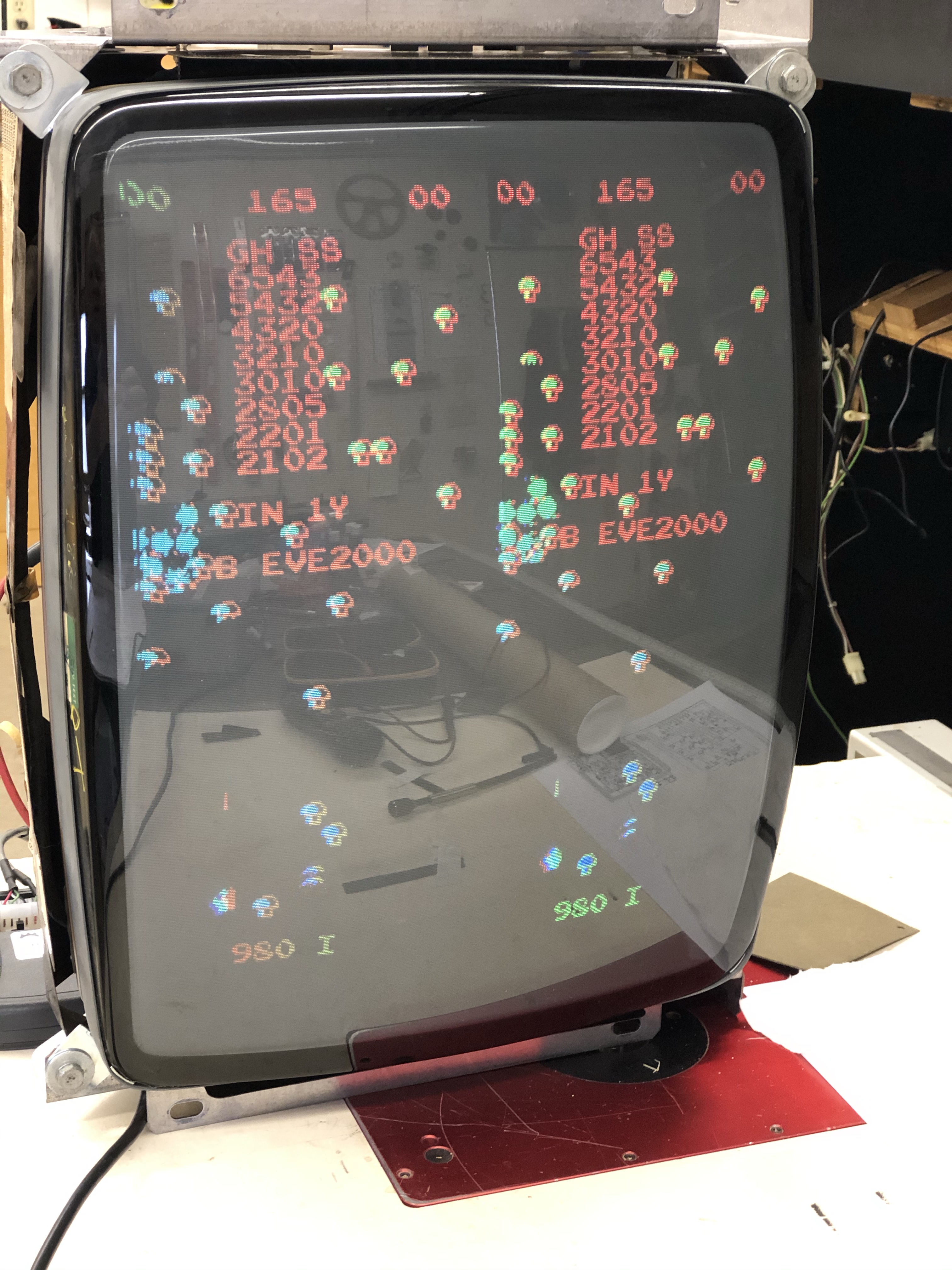
Here is what was happening! Twice the centipede, twice the fun.
It took me a while to think through it, but from this:
- Video memory is working
- Program is running
- Horizontal sync working
- Vertical sync messed up – explains why the LCD could not lock onto the signal
- Game played- in double bezerk more.. but it played.
The screen was doubled – but each side was sliced into 4 sections.
So whatever part of the circuit that scanned through the video ram was getting bad signals and was just displaying stuff out of order. The issue is vertical in nature since the screen is sliced horizontally 8 times
Working my way backward in the schematic, it took me to the sync circuit.

Just using a logic probe, I hit the 1v, 2v, 4v,….128v pins in this area. All of them were pulsing EXCEPT 32v! It was pinned high. Hitting all the pins with a logic probe tends to reveal patterns, this one was not following the pattern and it is right in the middle of the vertical sync circuit.
Ordered the replacement chip for N3 – 74LS163

I really wanted to try that thing where you piggyback a chip on a known bad chip.. The screen went all fuzzy, so that didn’t work. Must be for other chips, but not this one.
So I socketed and installed the chip and this happened! Parts of the playfield missing, rain drops. But it was an easy fix.. When I did the piggyback trick – it clearly fried the chip.. Note to self – don’t do that. I had ordered spares.. New chip installed
Board works!
During testing I determined high score retention was not working. Since the board had +15v and -30v in the right spots – I knew the only chip it could be was the ER2055. I had a spare, replaced it and high score retention is fixed.
Testing also revealed that the trackball response is off.. My other two boards work perfectly. This board if you spin the trackball quickly, it kinda skids and goes the wrong way for a bit – then catches up and does what it is supposed too.. I’d suspect the trackball itself (and it could ultimately be that) – but my other 2 boards work great.
There are only 2 chips on the board that can really be effecting this. One being 74LS157 at D/E 11. I’m going to try swapping it out first since its the most likely suspect.
Last item to fix is the trackball response (once the part shows up)
Replaced the 74LS157 – but no change. The trackball has the green boards which have been known to have this backspin issue. I’ll order a set of the red boards and see if it goes away. I’d still like to understand why 2 boards work correctly and the 3rd one doesn’t. Its likely a case of close tolerances. Maybe I’ll be able to trace it to be sure..
Replaced a green board with a red board and problem solved. Solution was well known. Not sure why 2 out of 3 boards worked correctly.. But this PCB is now 100%
Board #3
Purchased off eBay for a good price and training board
Triage:
Board dead – no picture or test mode
- All voltages on board good (+5v, -5v, +12v, +15v, -15v, +22v, -22v, -30v)
- Missing ROM#210
Work done:
Removed and cleaned legs of all chips that were socketed.
Verified/replaced missing and bad ROMS – 210 missing, 208, 209, 212 were bad
Checked for any hot chips (none)
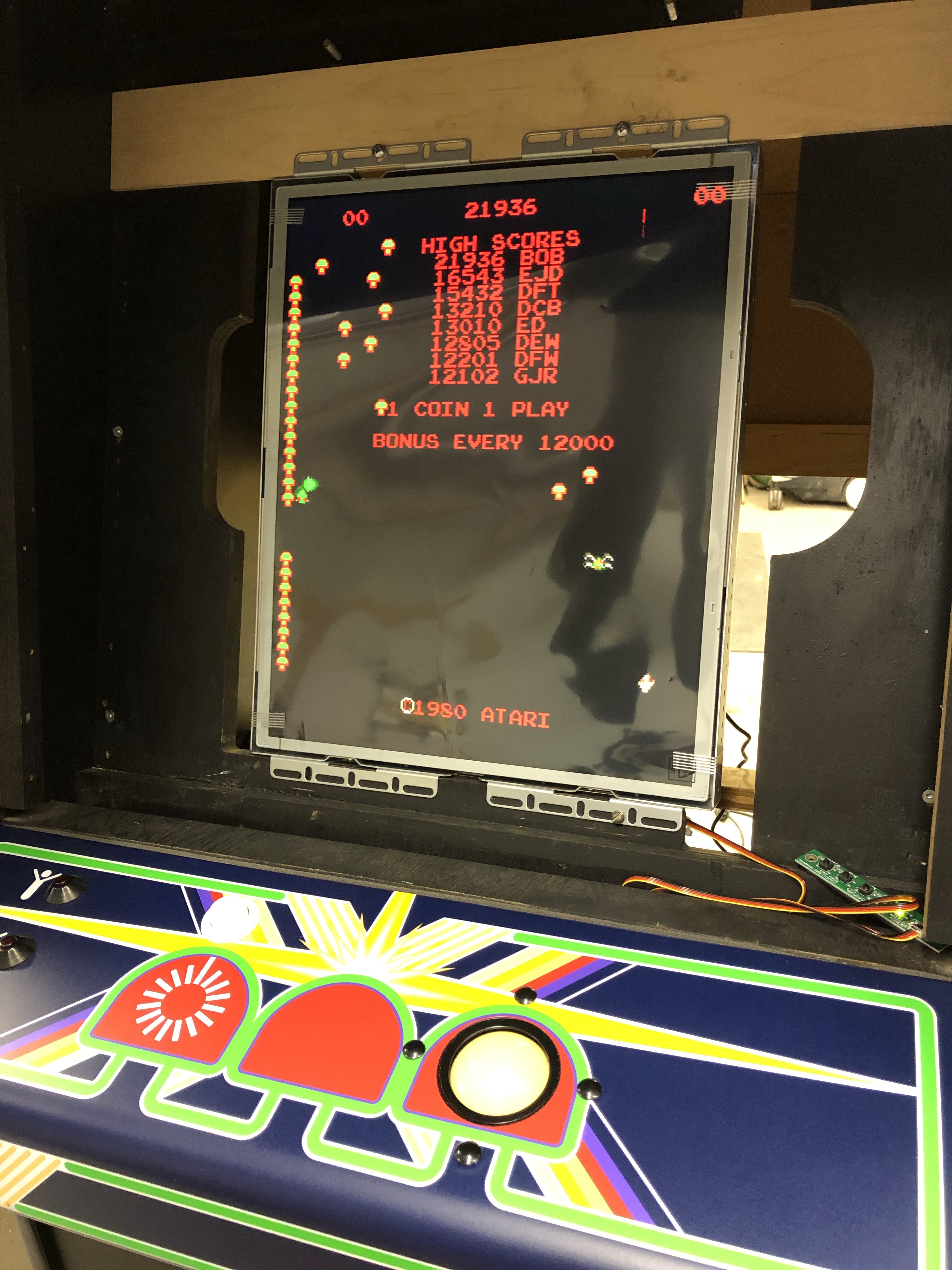
Board powers up and shows this screen:
This tells me:
– Sync circuit is working
– Video memory is working
– CPU is running
The watchdog circuit is triggering and when you put the machine in test mode it beeps at you. Testing pin 40 with the logic probe on the CPU confirms it.. It’s pulsing.
(New to me) trick I just learned:
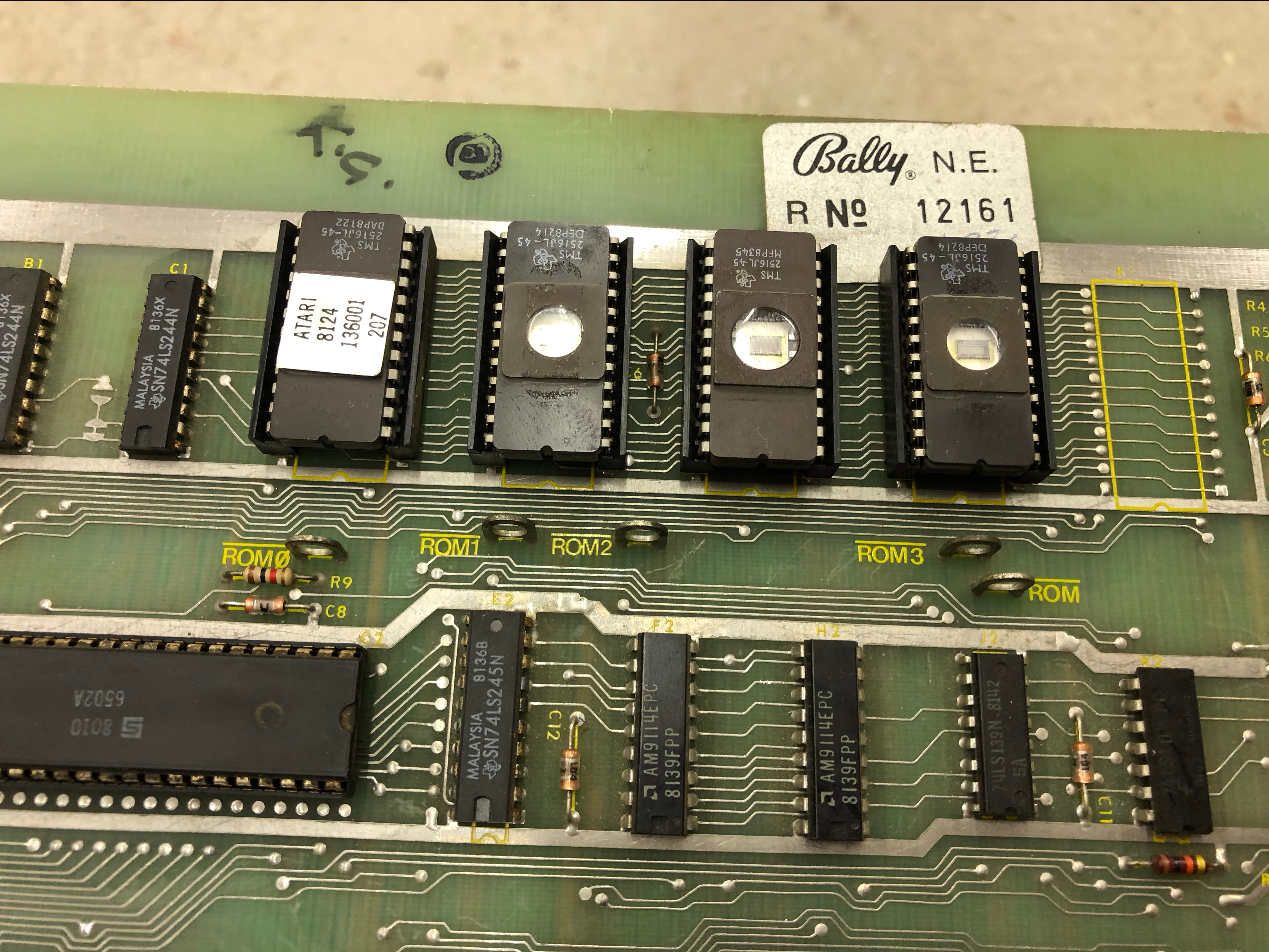
The ROM, ROM0, ROM1, ROM2, ROM3 test points make it very easy to determine if the ROMs are getting accessed. They should all be pulsing with the logic probe.
Turns out ROM0 is stuck!
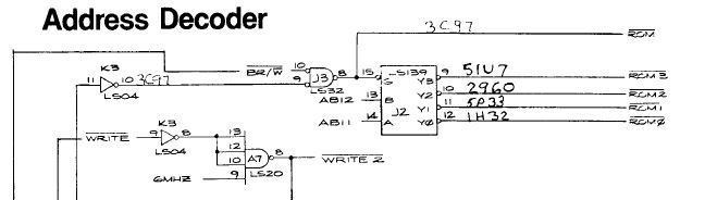
From the schematic, the 74LS139 at J2 chip is the one that cycles through the ROMx lines.. ROM, ROM1,2,3 are all pulsing and ROM0 is stuck high.. Pins 13,14,15 all seem to be doing their work. Next up is to replace J2 and see if the machine boots past the watchdog.
Replaced the chip at J2 – no change.
Learned yet another new thing:
On the Centipede board there is are test points to disable the watchdog circuit.
If you jump the disable watchdog test point to ground, the CPU will get to run the RAM check without the watchdog interrupting.
Once I did this it signaled RAM chip#2 as bad.. (A 2114 chip)
Replaced it and ran it again.
Then signaled RAM chip#7 as bad (A 2101 chip)
Waiting for that to be delivered….
Moral of the story: Make sure the RAM self test is actually running.. I thought it was.. turns out.. it wasn’t..
One more item for my triage checklist..
Replaced RAM chip #7 at M7
Board now passes RAM test and plays.
Background graphics are messed up however. I was able to play enough to test high score retention circuit (works). The on board testing says (per the manual) that color RAM C8 has failed and would not have been flagged in the standard RAM check. Need to probe to determine if its getting all its inputs, etc. before replacing.
I’m glad I waited before just ordering a chip, swapping it out and determining it was not the issue. In self test mode – you hit different buttons to do different tests.
The Background Color Test and the Object Color Test were behaving strangely..
Player1 Start is the background color test – it showed its bit toggling on the screen, but did nothing.
Player2 Start is the object color test – it showed its bit toggling, changed the colors of the letters, etc. But ALSO changed the background colors.
At first I thought the chip both of these connected to was the issue. (74LS257 @ L9) The trackball feeds that same chip and it had done a couple weird things is test mode. The troubling part was the bits were flipping and displaying correctly on the diagnostic screen in all cases.
These bits were obviously being picked up correctly on the data bus and being interpreted – or they would not display correctly on the screen. So the input circuitry was good and the code that displayed the switch positions was running.
The data lines the Player1 and Player2 switches used were DB0-DB3. So I decided to follow the data. Looking into the video output circuits – Maybe they were not getting clean information from the part of the system that controlled the background? The color ram at C8 (where the self test said the failure was) seemed to be working with the data lines pulsing in with the logic probe. I swapped in my known good board and tested C8 and both boards seemed to be behaving the same. Using just a logic probe – that is about the best you can do.
Moving backward though the circuit – it pointed toward the Picture Data ROM circuit. Reading though the description:
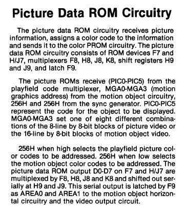
This had a lot of promise. I read this as: display some objects and then display some colors. Something to that effect…
Which caused me to focused in this area.
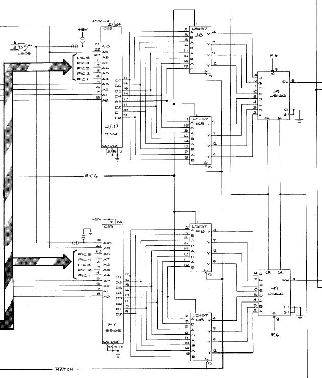
I started checking lines into J8/K8/F8/H8.. The lower set F8/H8 seemed to have some dead lines coming in (neither high or low) Compared to J8/F8 – they were behaving different.
F7 (ROM 211) was original and H/J7 (ROM 212) was a newly burned ROM. I had cleaned 211, Deoxit and reinserted. The board had been passing RAM and ROM checks at this point. Using the logic probe I worked my way around F7 just to see data was going in/out.. When I do this I touch all the pins just so I can compare with a component that mirrors it. Except – pin24 was not showing anything – wait – that’s power! I pulled the ROM and gave the pins a light sanding with 600 grit paper. Put it back, the game started playing correctly!
It seems F7 was sorta partially powered (pin 21) – that is why it didn’t flag in the ROM check and why some items seemed to work. I suspect the socket is flaky. I’ve ordered a replacement socket to make sure this board doesn’t end back up in this spot again.
After testing (playing) the machine for about 10 minutes – the screen had a burst of crazy graphics, the shooter changed to a line and 0’s popped onto the screen.. WFT?
I put it in test mode – it was watch-dogging again. So I hit the reset switch and it counted to RAM chip #3 (K7). Back to the bench, swapped out K7 and the board plays again. I’ll let it burn in over night to see if any other RAM is going to give out. Not sure if that is common or not. Having a chip die WHILE playing it..
Once the socket is replaced and its burned in a day or two – this board will be considered done.
Ran the board over night and tested – the socket is definitely flaky. Overnight burn in also caused the 555 timer chip in the high score retention circuit to fail. I’m going to run this board for 4-5 days to make sure the remaining chips are cooperative before calling success.
This board is putting up a fight:
Replaced the ROM socket at F7 – this cleared up the image instability.
The shooter showed a new odd symptom, intermittently upon game start – the shooter would move either all the way to the right, or up, or up and to the right. Once you moved the trackball – the game played normally. If the shooter does the self movement and I don’t touch anything – it will make the exact same motion through all three shooters during game play..
I first replaced the 74LS74 at D11. It is a common to both the X and Y direction of the trackball and maybe it was weak. No change.
Next I replaced the 74LS157 at D/E11 – It is the next chip common to the inputs and its closer to the trackball in the circuit. No change.
Last real chip (closest) to the trackball is the 4585B at E/F11. It is a comparator chip that I need to read up on to determine if it can start in some weird state and cause the issue. I have one green board and one red board in the track ball? Could it be some weird mismatch? Need to keep digging into this one..
The vertical and horizontal counters chips (C11, B11) are on separate 74LS191’s. It would not be likely that they both failed in the exact same way (moving the shooter w/o input) either. I’m pretty sure they are doing what they are being told. I’ll have to figure out what line is telling them the wrong thing.
During all of this – the high score circuit lost retention. -30V was still there. So the new 555 timer was still working, and score loss was also intermittent. It would retain for a while, then go away. I popped in a spare ER-2055 to see if it retains. Monitoring continues.
Next – the LM324 chip failed. Audio went half out.. Replaced it and audio is back to normal.
Is this board really that tired? Maybe the power is not clean at the board level?
(I was on the right track here..)
My other 3 boards work perfectly. There are a couple of capacitors on the input side at the board level that I will re-check to make sure they are doing their jobs.
Outstanding items:
– Continue to monitor the high score retention circuit
– Determine root cause of trackball/shooter movement at startup.
This particular board has been educational to say the least..
After messing with it and doing some testing with my new oscilloscope, I was as a loss to explain the odd shooter behavior. So I sent a video to a friend and he said “static?” After thinking about it for a few minutes, it explained everything.
SELF INFLICTED WOUNDS!!!
The first 3 boards I tested using an LCD. When I let them run overnight to burn in, I’d just unplug the 12v power cord from the monitor.
Since then I got a new monitor. It is a pristine K7203 that is essentially brand new. I’ve been unplugging the molex power connector from the back when I let boards burn in over night. The plugging and unplugging has been creating electrical noise that has caused a couple of these chips to blow as well as causing me to chase ghosts.
The board had legitimate issues when I started working on it, the last few repairs I will add to the getting experience bucket.
All future board tests will be on the LCD when checking for stability overnight.
Board works.
Board #4
Purchased off eBay for a good price
Triage:
Visual inspection – no issues
Removed all socketed chips, cleaned pins, Deoxit on pins/sockets
Tested all ROMs
- All voltages on board good (+5v, -5v, +12, +15v, -15v, +22v, -22v, -30v)
- ROM 212 Tested bad
Game plays blind – no video
Work done:
ROM 212 – Used UV Eraser, erased and verified the ROM, reburned and retested.
All of the video outputs were showing voltages, etc. at the connector for the monitor. Bad sync should have given me a scrambled screen – but not a blank screen?!
Quick check on what I should be seeing on the video connector:
- H-Sync – 15.75 kHz sync pulse
- V-Sync – 60 Hz sync pulse
- R/G/B – ~1-4 volts
Used the oscilloscope and determined I was getting both sync pulses. Checking R/G/B they were getting signals. The strange part was the baseline was up at 5v and the signals were toggling up/down – but this was my first time ever looking at it on a scope and I didn’t know it was wrong out of the gate. I just knew it had movement.
I swapped in a known good board to validate what good looks like. The baseline was at 0v with the signals pulsing upward on R/G/B. A quick check of the 7407N at A9 showed low voltages in and high voltage out. Replaced the 7404N.
Board works!
Board #5
I now have a bunch of boards I’ve collected from eBay and KLOV to continue repair practice.
Triage:
Visual inspection – no issues
Removed all socketed chips, cleaned pins, Deoxit on pins/sockets
Tested all ROMs
- All voltages on board good (+5v, -5v, +12, +15v, -15v, +22v, -22v, -30v)
(Not the same with the Jamma checker and the Jamma to Centipede Adapter – 15,22,30 all run low it seems) - Used Vector Labs Jamma quick check instead of sitting on a milk crate behind my Centipede machine.
- ROM 310 Tested bad – burned, verified and replaced
Game powers on with a screen full of garbage
– Video circuits working!
Work done:
Probed 6502 – no activity from most (if not all) of the CPU.
– Replaced 6502
Machine boots with a screen filled with ‘0’s on the lower half, board watchdogging.
- Bypassed watchdog
- Very faint sound, piggybacked LM324 – sound! Socketed and replaced.
- Diag test reports bad RAM at K3. Socketed and replaced. No other RAM reporting bad.
- Diag mode shows normal Centipede test screen, coin and start buttons work, colors change.
- Board still watchdogging – so primary code not running.
- Probed address lines, etc.. no clear issues.
- Flexed board along the edge – game started. In and out.
- Replaced ROM socket at F/H1 – Game runs.
- Tested high score retention – didn’t work. Replaced ER-2055 @E5. High score retention works.
- Game Works!
- Will replace the other 3 sockets in the row for stability.
- Went back to do a final check, board started doing crazy things. Screen jumped and the high score went back and forth from the default to one I set a couple times.
- Ran self test – 2114 RAM at F2 flagged as bad
- Rechecked again
- 2114 RAM at H2 flagged as bad.
- Washed, dried and defluxed socket work.
- All socketed chips Deoxit’d
Board #6 (I think)
It’s been well over a year since I worked on a Centipede.. Fixed many other boards since then.
Triage:
Board watchdogging and booted to all red screen or booted to garbage. No sound or beep codes. Tested voltages, needed a 7815 regulator.


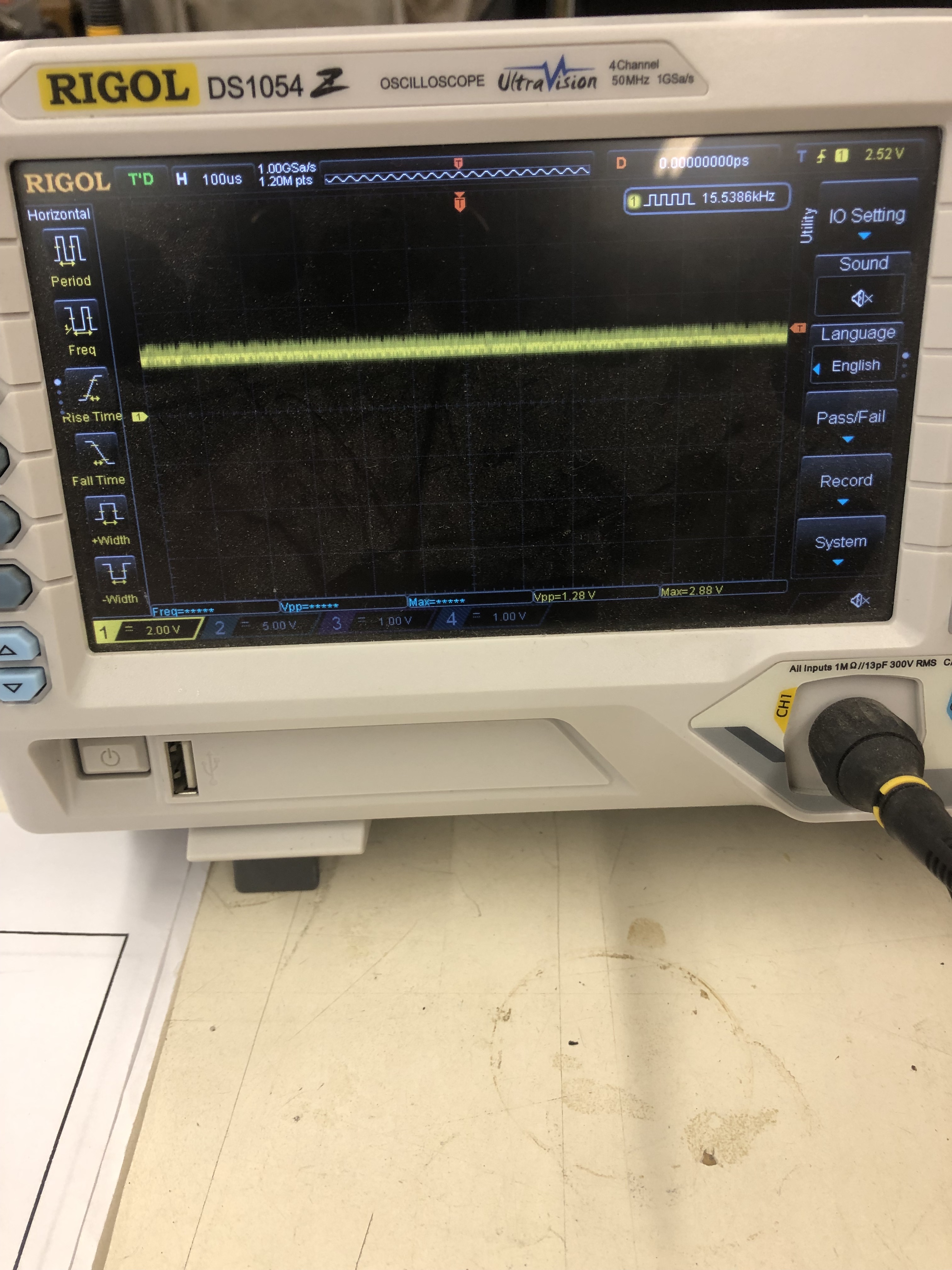
Checked CPU clock signal, looked good on the scope (more on this later).
Looked at RAM signals and D4-D7 looked bad on the scope vs. D0-D3. All the address lines looked normal.
- Tested with known good ROMs – no change
- Pulled socketed and tested RAM @F2 – no change
- Pulled socketed and tested RAM @H2 just for completeness – no change
- Spent some time trying to figure out what was messing with the D4-D7
- Centipede is pretty simple on the booting side of the CPU
- Address lines all looked good, etc.
- Went back to the beginning and probed all the pins on the CPU (more than once really)
- Then something caught my eye.. The CPU clock frequency was toggling back and forth from 1.5mhz to ~750khz on the scope….
- Worked my way backwards though LS244@B1, LS107@L4, LS32@J3, LS42@H3 – testing, probing, following the slow clock.
- Got to the LS32@E3 – which is attached to the input side of the PF(active low) signal.
- Piggybacked a new chip and the game booted into test.
- Experience +1: Don’t just check for clock – check for CLEAN clock – I had not run into this before. Having a clean screen of properly synced garbage lulled me into thinking the clock was fine.
- Game booted into test – beeped out a bad 2101 RAM @M5
- Replaced RAM
Board works!
Board #7
Received a board in for repair.
- It beeped out RAM failure at L5
- Replaced RAM
- Did general maintenance, cleaned chips, etc..
- Board was ‘crunchy’ when flexed.
- Cleaning/Deoxit legs makes me think it will be more reliable in this case
Board works!
Board #8
Received a board in for repair.
- Reported that DIP switches not setting allowing 3 shooters
- Edge connector is burned up
Repaired edge connector and tested board.
Can’t seem to find any issues..
Board works!
Board #9
Received a board in for repair.
- Reported explosion sounds messed up
When I received the board – it had this on it..

My first assumption was that this was involved with the sound issues, especially since it was adjacent to the LM324 audio amp.
What this turned out to be was a mod to make this early -01 revision board look like a later revision board when it comes to the Trackball.
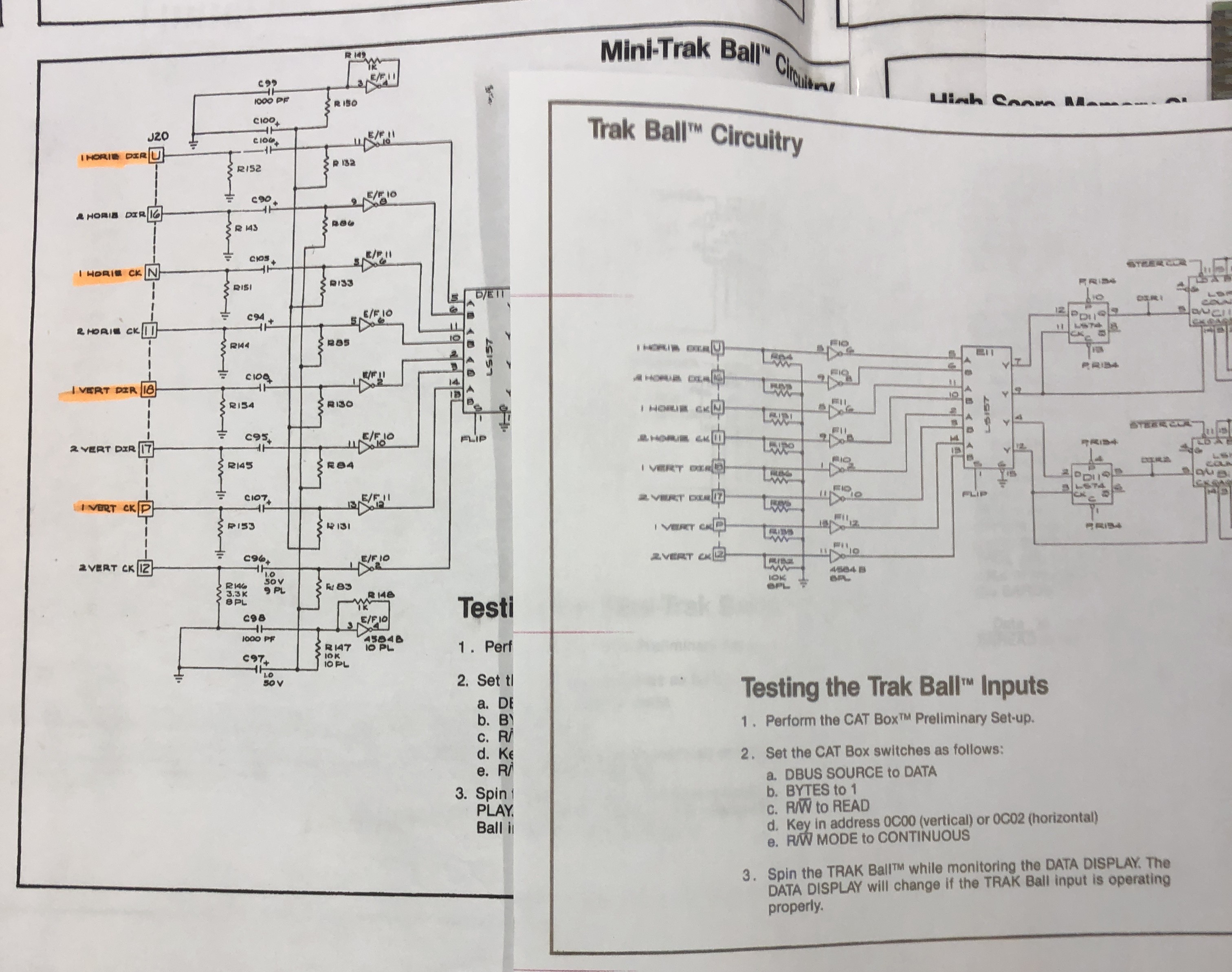
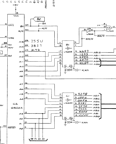
The early revision schematic is on the right and the later revision is on the left. Someone decided to add all the parts to make it a later board. It actually worked! That said I wasn’t leaving it like that and I returned the board to ‘normal’. The sound issue remained – the explosion sounds were way off. But most of the sounds were normal.
Another thing that was going on is it amplified a sound I never knew was there in Centipede.. when the spider is hopping across the screen it makes the normal ‘spider’ sound .. but there is a chirp that happens (almost like a single cricket chirp/click) I had never heard it before.. It was noticeably loud – I turned on my machine and it is there.. but very very faint. I have many hundreds of Centipede hours and never noticed it..
That said – there is almost nothing going on after the Pokey except the LM324 amp.

I replaced the LM324@K10 and all the sounds are back to normal. Seems like it over amplified high frequency sounds and corrupted the low frequency ones.. Interesting failure.. They usually just die..
Board works!
Board #10
Board in for repair – cleaned chips, etc..
Had to remove solder blob from edge connector fingers, otherwise a very nice board. Had mushrooms all down the left side – bad Pokey.
Replaced Pokey
Board works!
Board#11
Got a board in for repair – It’s origin is from this thread on KLOV. Reported colors washed out after being powered up for a while.
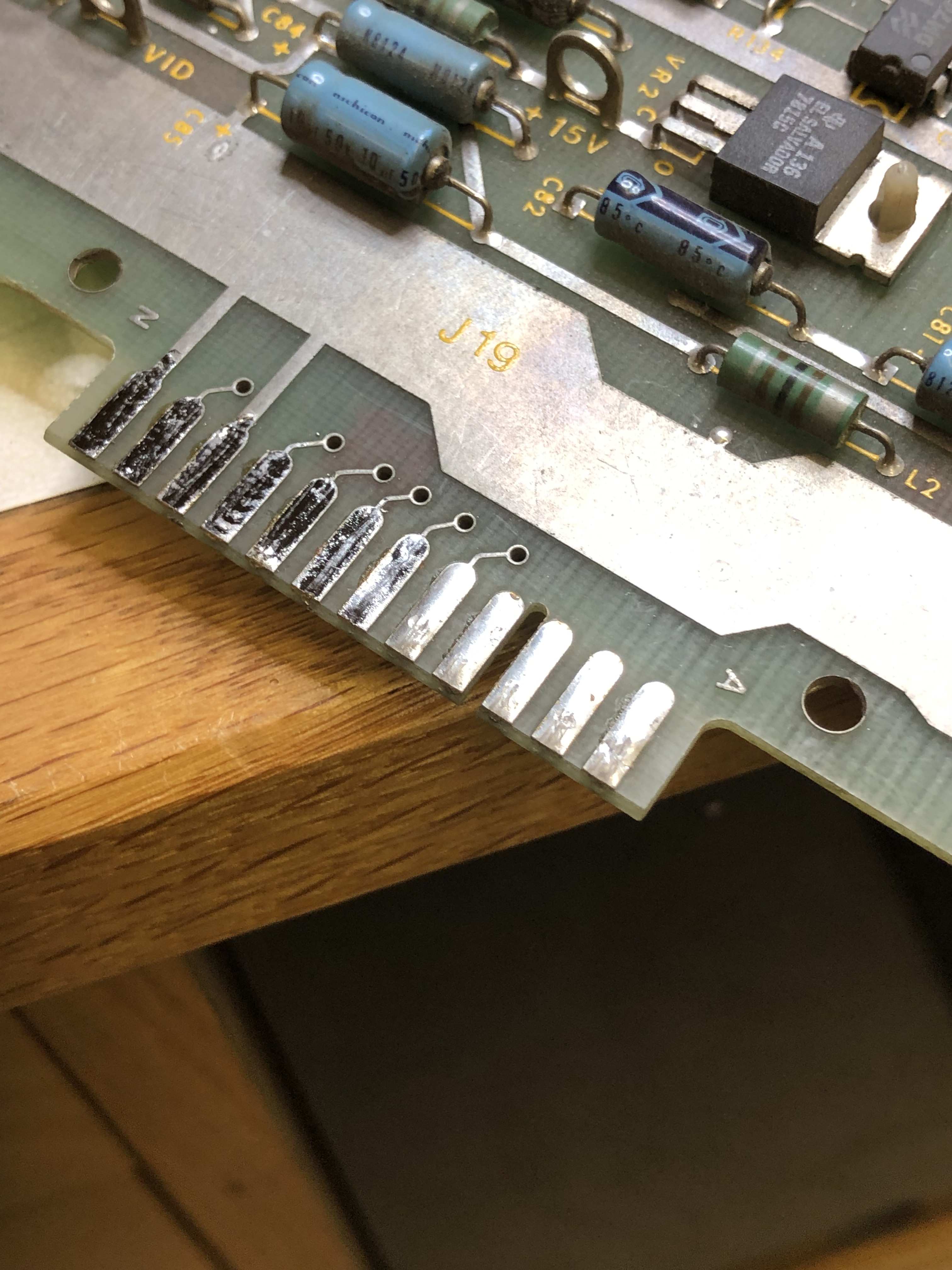
When I received it – first thing I had to do was remove the solder blobs on the edge connector.
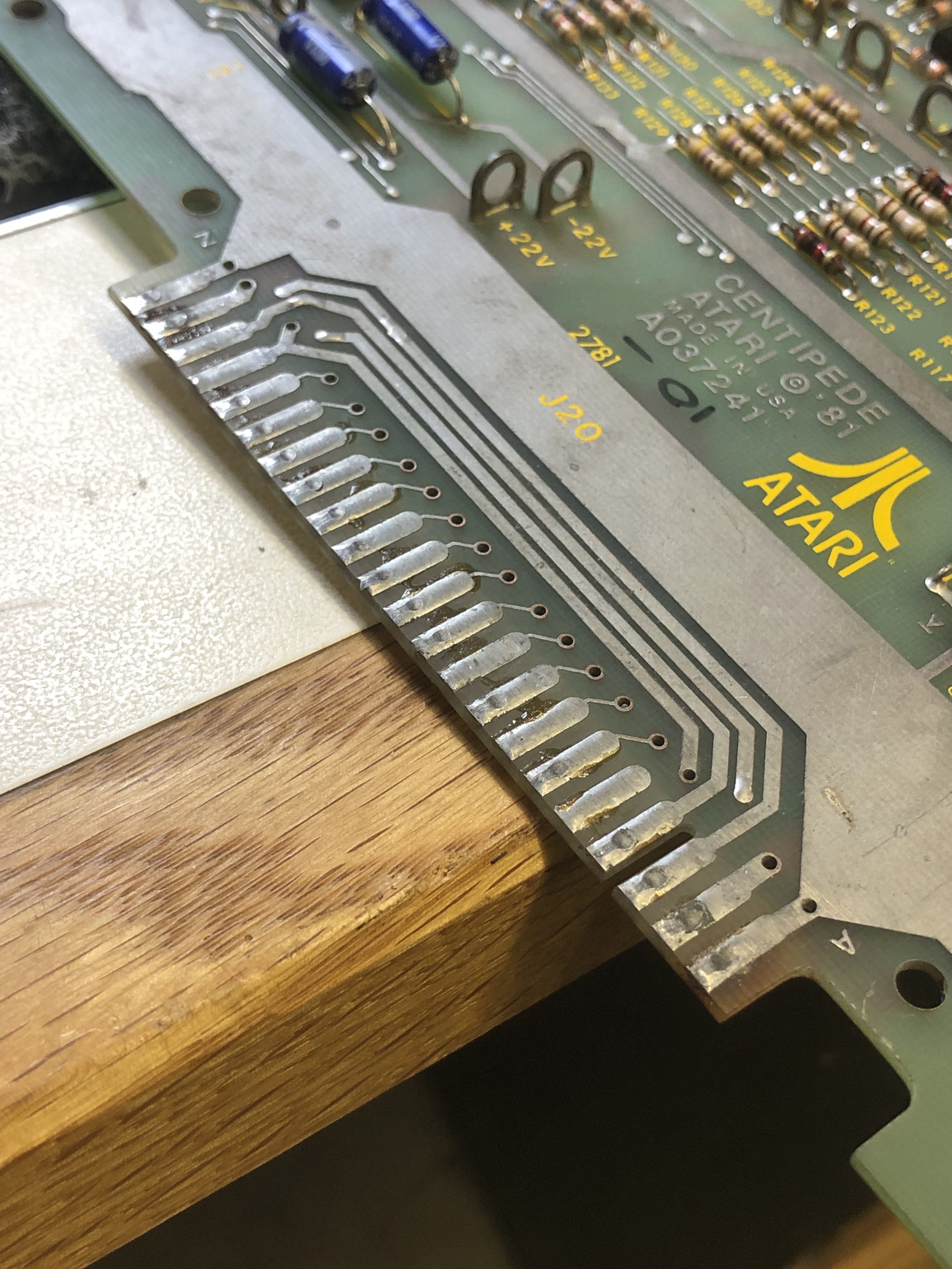
These were very neatly done – but they are really thick. Look at those divots. After removing the excess, a number of the fingers were not very well attached at the ends.
Here is how I like to repair them:

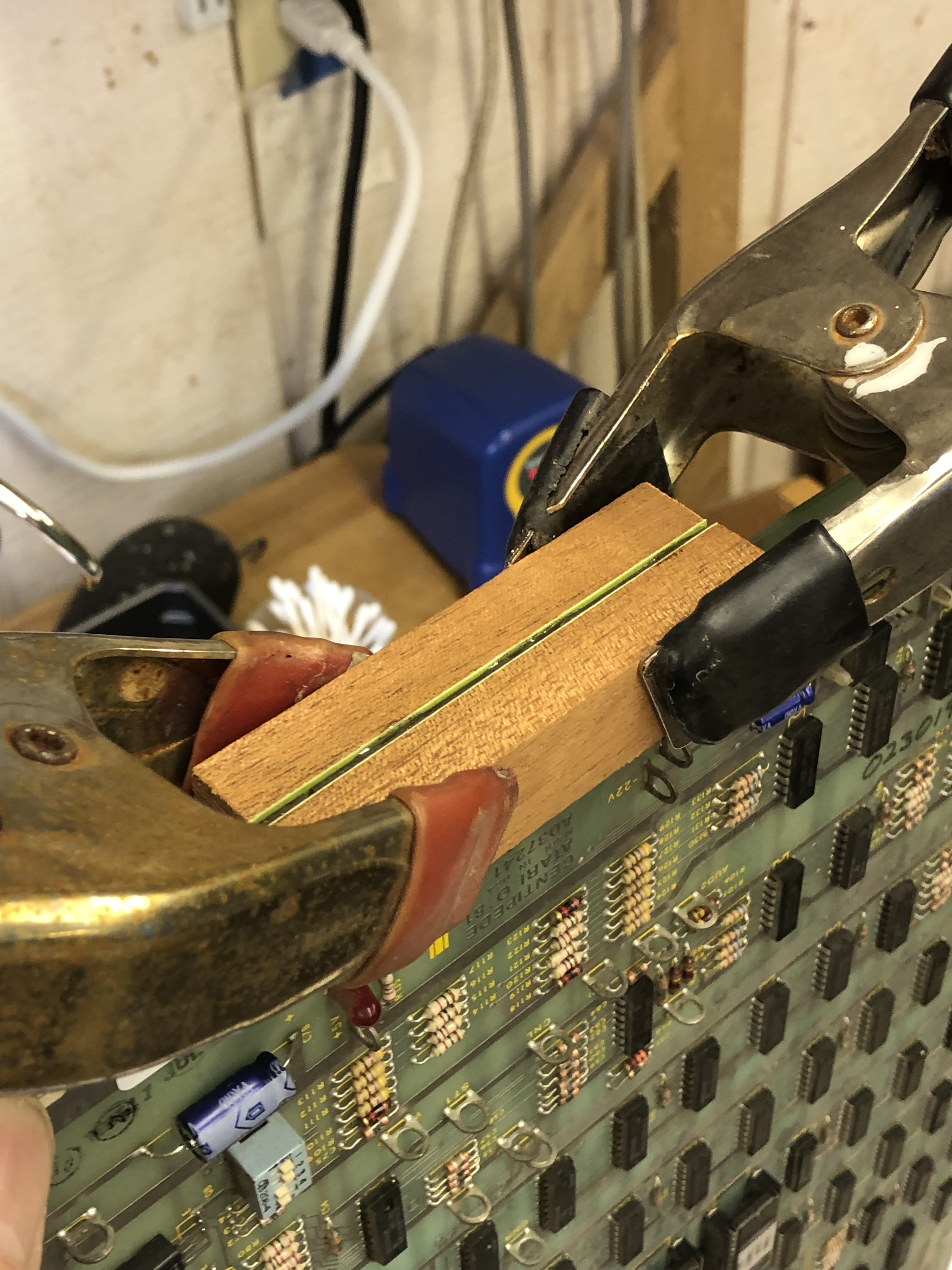

After cleaning the area with acetone, the lifted fingers each get a drop of a slow cure 2-part epoxy. The slow epoxy bonds better in my opinion than 5 min epoxy or super glue. These two hardwood blocks are very flat. I put 2 layers of masking tape and an outer layer of clear packing tape on them. Epoxy will not stick to the packing tape. A couple of spring clamps and ~10 hours later, here is the glued up edge connector. The masking tape provides just enough padding to firmly clamp the fingers and compress out any excess epoxy on the sides of the fingers. Those little epoxy valleys really help hold the traces from the sides too.
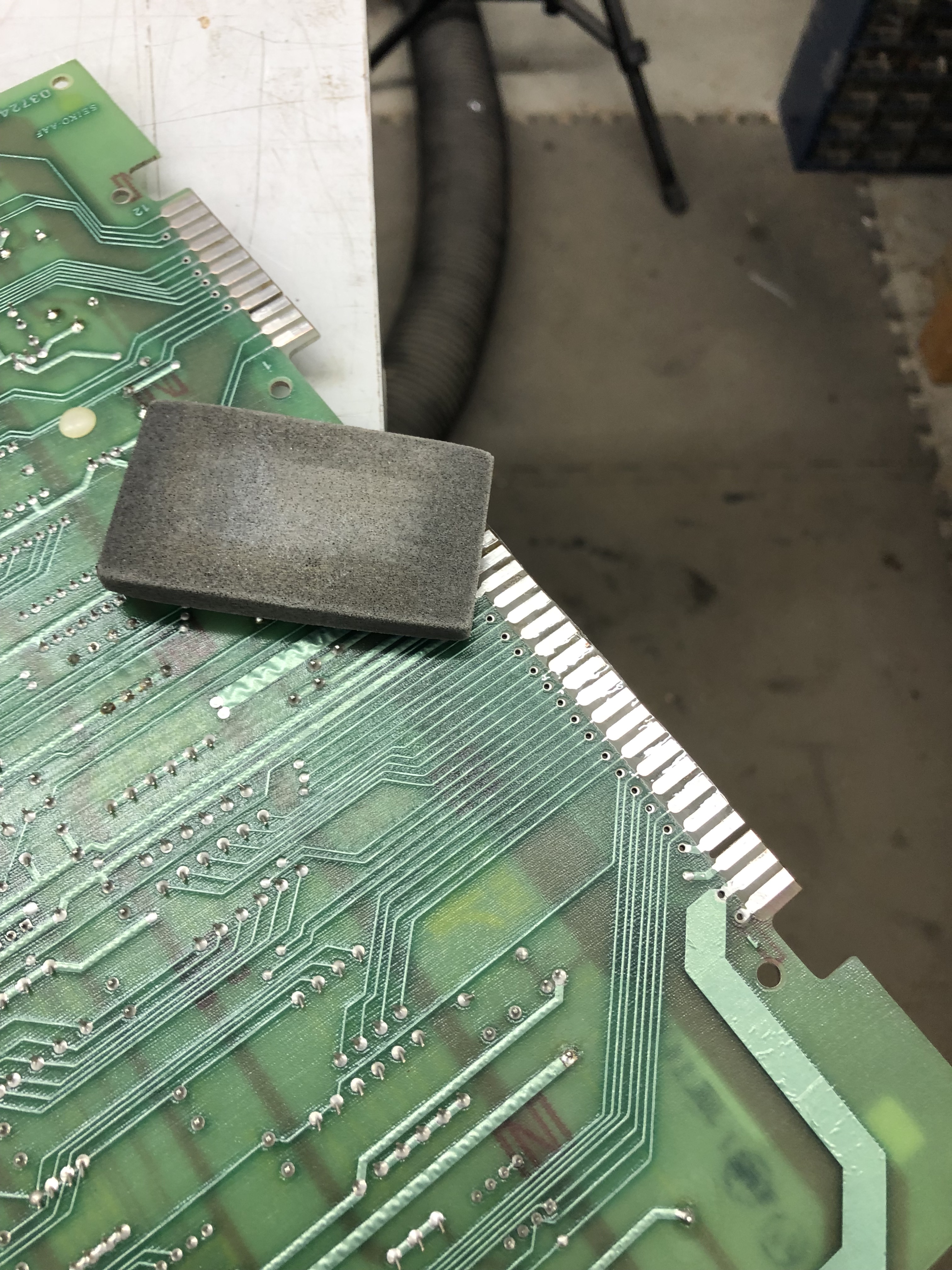

The epoxy does stick to the outer surface of the fingers however, a VERY light polish with this block removes the surface glue and leaves a clean connector. It will get a coat of liquid tin as a final step for a little extra protection.
Moving on..
After connecting the board to my test rig, the board was fully locked up. Start button on, no sounds, no diag. Connected to the FPGA Catbox and one of the ROMs wasn’t seated very well (hadn’t cleaned chip legs just yet) – All RAM /ROM passed. Hooked it all up.. Board is now watchdogging. Popped in a replacement 6502 CPU. Board stopped watchdogging and no video, I could get it to play blind. This was due to a sync issue with the PROM@P4 not being cleaned yet as it turns out..
It was mentioned in the KLOV thread – the 7407@A9 was not cooperating.

The output side of the driver was stuck high – causing the washout that was mentioned. I would have expected to have seen it, I use an LCD on the bench because it takes up less space. It doesn’t always render bad signals. Replaced the 7407@A9 and the board ran with video for a while and then died.
During the time it had been running, the audio volume was very low. All voltages had already tested good. Socketed and replaced the LM324@J10. Full sound restored.
At this point, the board would run an hour or so, then I would find it fully locked up. Reseating an EPROM would seem to free it. After a couple rounds of this I replaced the 4 EPROM sockets in column 1. Just tapping them could cause a reset. They were the Atari gold pinch style which I’ve found to be a bit hit or miss.
Clearly this board had not been run in many years, more hours of burn in time brings more failures. Next was the board stuck in hard reset. Nothing working at this point. I was probing the reset circuit and sorta burned my finger brushing up against this..

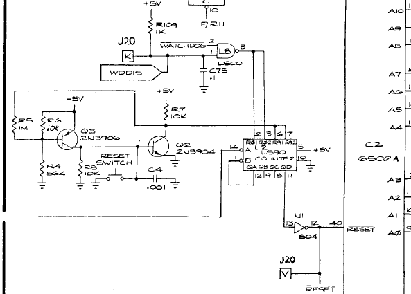
Q2 was burning hot and had already cracked. I powered down and determined that the 74LS90@L2 was shorting Q2 and burned it up. At least it finally failed. I was out of them so I borrowed one from a donor board. Then chased a ghost for a while until I realized the donor LS90 was also bad, it just wasn’t burning up transistors. Got another one and the board now watchdogs and resets correctly.
Next – I tested the high score save circuit. It also didn’t work. Had proper voltages, etc. Checked the EAROM with the FPGA Catbox and it failed. Probing while running a few tests showed that the 74LS374@H4 was getting data signals in – but not putting the data on the bus to the EAROM. I had swapped in a known good EAROM during this time.. Went back to the original and determined it was bad too.
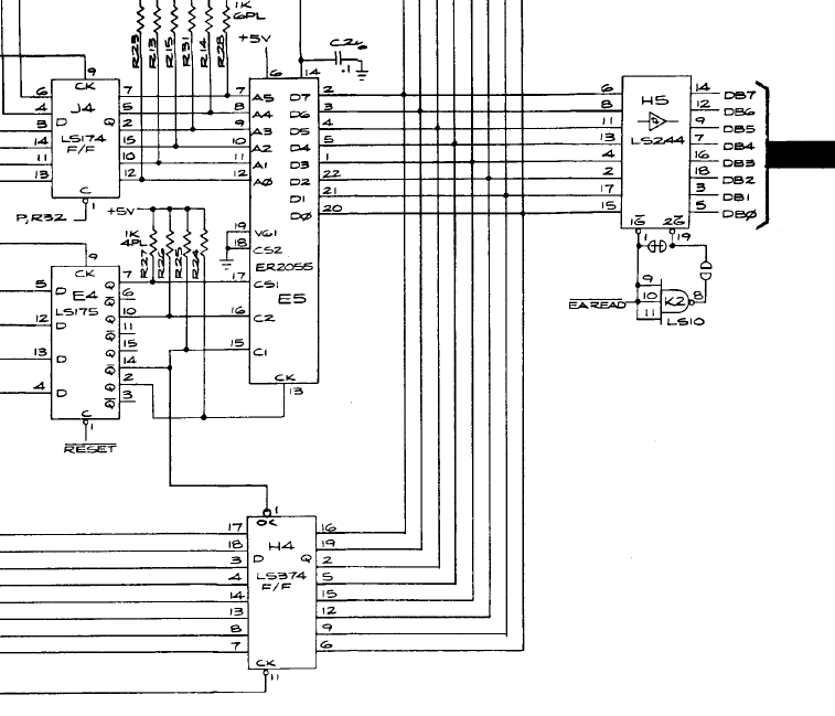
Replaced LS374@H4 and ER2055@E5 – High score save working!
Well, it happened again – I went out and checked on the board. It had been running a solid 12+ hours at this point. The start LED was locked on solid, I figured it was stuck in reset or something again. Ughh.. I turned on my monitor (no need to leave it on all day, right?) and there was Centipede – running normally with 13 credits. But the LED was locked on? Seriously… The LED circuit was broke. Did some tracing with the scope…

I checked @M10 pin 7, but the chip looked like it was doing what it was being told. The OUT0 signal looked pretty bad.. Just a small spike sorta pointed down on the scope.

When to the LS32@F3 Nice clean signals going into Pin 1, Pin 2 – and nothing bug ugly out. Replaced LS32@F3 Start button blinks properly again..
The wait continues .. who’s going to die next..?
Well let me tell you, during the second 12 hour burn-in, I noticed both start LED’s locked on. Powered on the monitor and it has lost sync. I’d seen this one before early on.. I narrowed it to the PROM@P4. It appeared to be thermal at first, but 10 hours? I hit it with freeze spray and the issue went away and came back. The second time I just pressed it and the issue went away. Seems like the socket loses tension over time? I replaced it..
Decided to run an automated burn-in test I coded on a smart outlet. It powers on for 30 min and powers off for 60 min. Total of 16 cycles (24 hours). Not surprisingly, the board died again.
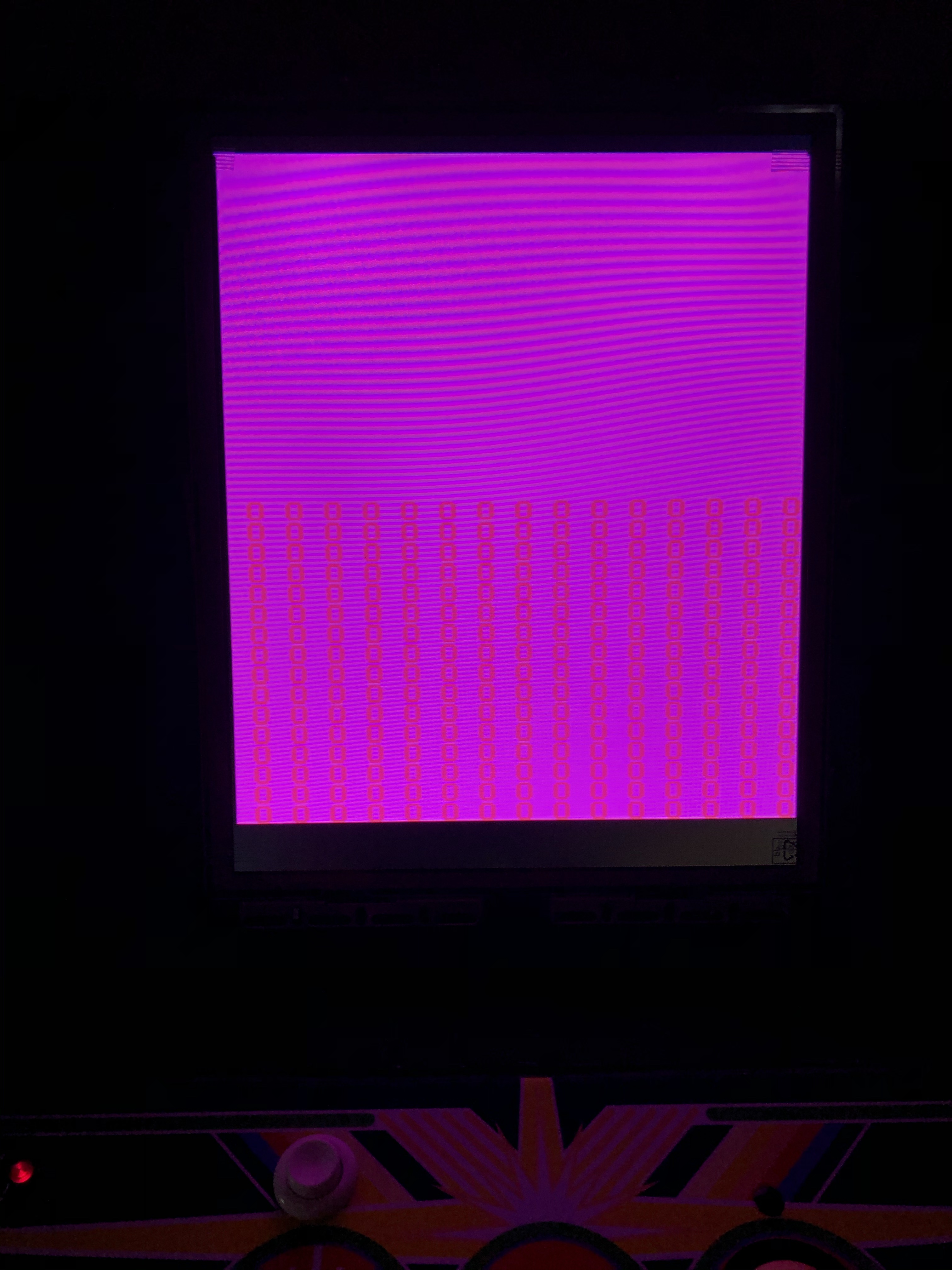
Turning on the monitor:

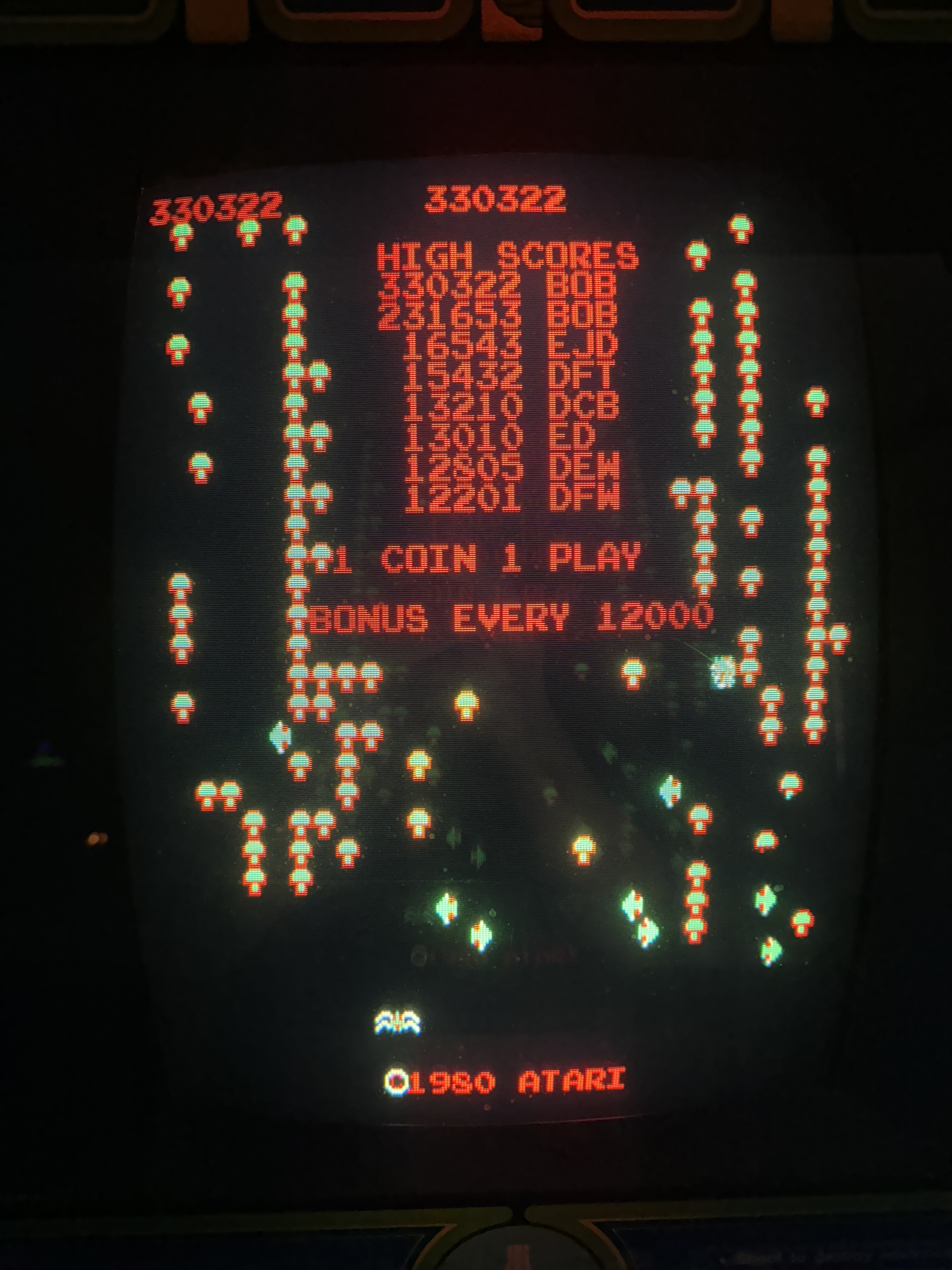
Perfect grid of white dots with 2 little pink/red squares in the center. I’ve worked on a lot of Centipedes and I’ve never seen this one. Probing I determined the game was not in reset and it was NOT watchdogging. The WATCHDOG was getting cleared by executing code. Still it was locked solid. Hitting reset would flash a ‘normal’ screen of ascii characters on a white background. I pulled a socketed RAM and got it to start beeping – but it was just beeping continuously, not a location. The only ROM getting accessed was the one with the self test code (@J1).
All that said – it certainly seemed like a decoding issue and I probed though those circuits and they all seemed like they were working. I did suspect the 74LS42@H3, but didn’t want to shotgun it … and it was getting late. Came back in the house and decided to do a quick KLOV search.
Found this thread from 2012 with a posted solution in 2014 by a 1 time only poster. I popped in my working board, shorted pin 3 & 4 of the LS42 as stated in the thread and recreated the issue. Replaced LS42@H3. Board is running again.
Not that I want to jinx myself – I re-ran my 24 hour power cycle test and for the first time – this board has survived a complete test. I’ll run a few more burn in sessions before calling it done.
So far – these guys are the trouble makers. There is a bit of a theme here…
Board works! (for now)
Board #12 – Board in for repair
Got this one from a friend to get working again. We had discussed the symptoms and just like the last board…

It boots directly to a screen full of dots with two little pink squares in the middle. He replaced the LS42@H3 – but in this case it was not the issue. If you look close it also has two rows of dotted lines at the top.. I’ve never seen that..
Knowing that this was caused previously from Pin 3, 4 on the LS42 ..

I followed the pin 4 output to the LS32@E3.. Pin1 and Pin2 inputs were good.

Pin3 output – not good at all. My friend had checked it with a logic probe.. He really needed to pull out the scope! Game boots now!
However..
This issue I chased for a while. At first it seemed thermal because it would ‘ram up’ with time. But that was not the case, the colors would change after a time..
I looked at the horizonal output part of the schematic, but it moves ascii characters around and this seemed later in the circuit. One thing I did was just remove the character ROMS@F7, H/J7
Another helpful moment and trick I found was to shut it all off. I pinned the MATCH line to 5v+ and shut off everything(?) in the graphics circuit.

Still getting video noise with everything shut off (I believe). Color mapping could be hiding stuff in theory..

I poked around here for a while and tried to see if I could back trace the noise.. Pinning the MATCH line high did shut off most of the data coming into this circuit. The address bus lines were the only thing really doing anything. One item of note early on – The game had a 6502, not a 6502A. I had put in a 6502A – at the time it didn’t make a difference.
I had been back to these two LS244s a number of times. I did Slice and signature analysis on them and they were good. But I happened to piggyback the LS244@B1 and all the noise went away?!
Replaced it and it is still gone. I’d replaced a couple of chips that seemed to be involved only to have them not have any effect. Oddly – I put the original 6502 back in and the trouble returned. So 6502A it is.. Root cause is likely some impedance, noise or timing issue ? Nothing jumped out and I checked each pin. I followed all the lines coming out of @B1 and they seemed ok.
Adding to the complexity – the PCB does not completely match the schematics. I looked for a different revision, but could not find one. Learned more about Centipede for sure..
I gave it a good workout, Board works!
***** Some late breaking news ****
After reading the post, my buddy sent me this pic from the LS42 he replaced..

It originally had this cap attached, but it didn’t make it to the replacement LS42. I popped the original 6502 back onto the board and the noise returned, nice!

Went into my stack of Centipede boards and found one with the same (factory) modification.
Pin 6 to Pin 8 – part of the COLORAM signal – which is where I had spent some time AND where this version of the PCB doesn’t match any of the schematics that I could find. 330pF mica cap.
Moved this cap over to the board under repair: Noise problem resolved again!! But this time with the 6502 (not the 6502A) in place. The donor board had a 6502 on it.. Clearly a very early revision of the PCB.
Still, I learned a bunch about the board and I have a better idea what to look for in the electrical noise department – Next time – I’ll just pop a cap in it.
Board #13 – Friends board from an arcade party
I traveled to a friends house for our yearly arcade gathering. This time I was asked to do a PCB repair ‘demo’ and show how I do things and my approach. One of the guys had a few Centipede boards and I recommended we used them because they are a good sample PCB.
Once we got things set up.. The board ran, but had some issues.
There are two issues here. First the background color is obviously wrong and if you look, the motion objects (sprites) are all broken up and divided.
In real time, we worked on the background issue first – didn’t find it quickly. Worked on the sprite issue and did not find that quickly either. I wasn’t in my shop so things progressed a little slower than usual. I had my full size Centipede schematics with me – but somehow lost a page adding to the difficulty level. We had them on a laptop, but full size is nicer.. I never misplace stuff like that..

We probed around this area for a while and all of the chips (C8, A8, A9) all had inputs and outputs. So one of them was doing what I like to call, bad math. The signals into and out of A9 all looked good. So I ruled it out. At this point we swapped in a working Centipede and checked the outputs of A8 vs the bad one.. The signals out of pin 11 were inverted – explains the background being stuck on.. Except the inputs also were inverted (or seemed to be). The color RAM@C8 seemed to be the issue. We desoldered the known good one (and socketed it), then desoldered the suspect one and swapped them. Colors restored to normal!
Next up was the motion object issue. I didn’t get a video of it with the background being black, but the Centipede, shooter, spiders and fleas all were sliced up. The Centipede rolled off the screen and wrapped and changed direction in columns. These all told me counter issues.

At this point the party portion of the day started up and this got set aside, somewhere in all of this we got my friends Sea Wolf II PCB stack up and running. We had spent plenty of time probing the motion object circuit. Again, every chip was running, someone was doing bad math. Early on I suspected the LS83s@H6 and F6. They had vertical counters and a ground probe on the pins caused the sprites caused them to do more weird things vertically. Not to be beaten, I took the Centipede board back to my shop as I just ran out of time and had to fly home.
Once back – I again probed this area with the scope looking for just the right chip causing the problem. None were conclusive. I then pulled out the Slice tool and it was telling me both LS83’s were bad.. Removing both of them and testing in my TL866…

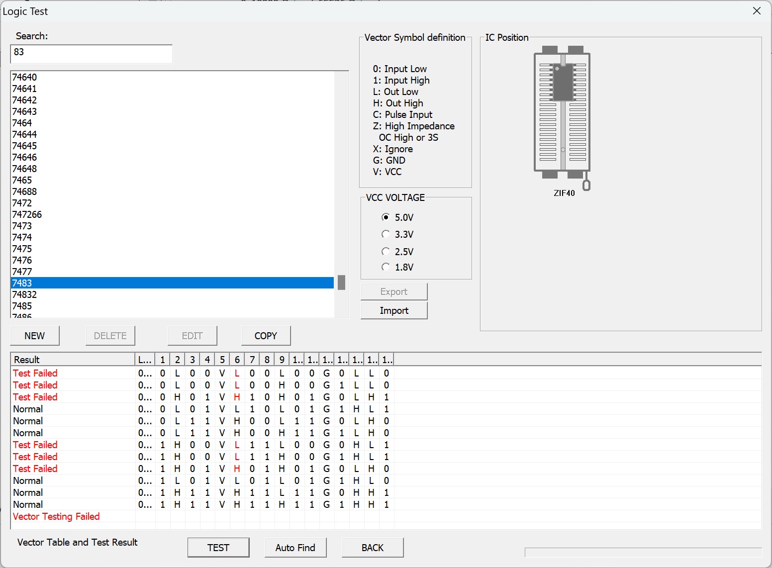
Both tested bad, Signetics brand.. Not surprised. I’ve found almost all the time – 74LS83’s fail by doing bad math vs. having dead outputs. Same chip messes up Tie Fighters on the Star Wars stack.
Replaced both – motion objects restored!

At this point I realized there was no sound. Replaced LM324@K10.
Board works!
Board #14 – in for repair.
This one was relatively simple. Board beeped out bad RAM @L7. Replaced it and board works.
Still did chip cleaning and full burn in cycle – over 30 hours of run time. On the last cycle, this happened..

The interesting part was it only happened on power up and could be cleared by the reset button . Power on/off right after that and it would be fine. Let is sit powered off for 10-20 minutes and you would either get white background or sometimes black background and white lettering. Because it only happened intermittently at cold power up, I looked in a few different areas just to be sure.
It took a little time to be sure, but in the end – the color ram was partially failing.

Color RAM@C8 was testing good, but seems to fail on initial color palette load occasionally.. Had to test a few days and cycles to be 100% sure.
Board works!
Board #15 – in for repair…
This one started pretty simple
Self test would not work for some reason, game ran, but it was a mess. Connected up to tester – all ROM good and a bad RAM@F2. Replace it and it seemed 100%! Should have been easy, right?
Then this repair turned into an interesting test of will… If you are a computer nerd.. read on..
Once it was running, I performed all of my normal board maintenance – clean chip legs, edge connectors, Deoxit, etc.. Then I add a credit and start a burn in cycle. Day 1 is run 12+ hours with a credit and make sure it doesn’t reset. Not too long later.. credit was gone.. game reset. When this happens I run it a day and see if maybe the bad chip will fail completely (usually a RAM).. not this time. While working on other stuff, I added a credit and it reset after about 10 minutes. After a few of these I started timing them and it would reset in attract mode, after 9 min 10 seconds and the next screen change. (this will make sense in a minute).
Had to be some weird software issue? Right? I swapped all the ROMs – no difference. Replaced the ROM sockets just to be sure, no difference. Once the pattern became more apparent I narrowed my testing approach. The reset was coming from the watchdog circuit. I clipped the scope to it and determined a watchdog reset was happening. If I disabled the watchdog – it would run forever..
So far the only issue was the game reset after 9+ minutes..
Would it reset during gameplay? Fortunately Centipede is my best game. Every 10K points is about 1 minute of gameplay. I played 2 games well over 10 minutes (~170K and ~220K) and the board did not reset.. So only in attract mode? One thing different about this board is it is a -01 hardware release. It is a bit different than all the other revisions and the differences are not documented on the schematics as far as I have seen.
Could this be a weird bug related to this hardware release? I went through my pile of Centipede’s and had two -01 boards. I repaired one .. tested it.. no resets.. Just to be 100% sure, quickly repaired my second one.. tested it.. no resets.. Whatever is going on, it is specific to this board and is not revision dependent.
Around now is when I went to: https://github.com/historicalsource/centipede and started reading Centipede source code.. I wanted to know why it always died at ~9 min 10 sec +
LDA FRAME+1
BPL 52$     ; Every 10 minutes...
AND I,7F
STA FRAME+1 ; Reset counter
JSR SWAP    ; Swap screen to clear memory errors
JSR SCORES  ; Display high scores
Here is the code that does it.. The FRAME counter ticks 60 times/second. If it rolls over 0x7FFF (32,767) it falls through to ‘JSR SWAP’.. (JSR = jump subroutine)
Remember earlier when I mentioned it was very consistent?
32,767 frames / 60 ticks per frame /60 seconds = 9.1 minutes. Exactly when the board watchdog reset at the next screen change in attract mode. At least I determined where the 9 min ~10 seconds came from.. However, it should not watchdog reset. This is just a catchall error check and good coding practice from the original developers. They clear the attract mode every 9 minutes to refresh the screen.
I had a lot of theories at this point.. One was how it was counting..

Hidden up here in the LS257@K9 – the VBLANK signal is read and toggles a bit 6@0C00

Here is the main code loop for Centipede, I saw VBLANK, IRQ and WATCHDOG and spent time trying to determine if the interrupts were running correctly (seemed to be as compared to a known board). Checked what I could around VBLANK, etc. Swapped in a new socket and PROM@P4.

I checked frequencies, etc. with the scope – thought maybe there was a blip causing a reset.
I was running out of ideas.. Since it was just attract mode and only lost a credit after 9 minutes.. I started going through my testing checklist. One test is make sure I can start 2 players and check cocktail mode..
Started a 2 player game. After Player 1 died – game immediately reset going into Player 2.. REALLY?! Had to be related.. Something is crazy on this board.. I also tested with scoring on Player 1.. when it ended .. it spent all the time rebuilding all of the half shot mushrooms as it totaled up points, then reset as it went to Player 2.
Trying to determine what the attract mode and Player 2 situations had in common, both had ‘JSR SWAP’ right at the time of the reset among other things.
Looking into SWAP – Centipede does a very smart thing. To preserve the ‘mushroom’ layout for each player screen, the SWAP routine reads in 8 tiles and bitmaps them into a single byte. The entire screen is preserved in 160 bytes of memory. But this was all CPU and memory moves, it didn’t depend on any of the chips that were not already working correctly (as far as I could tell).
During all of this I used a comparator and checked a lot of chips in the clock, watchdog and IRQ circuits as well as verified items with my scope against a good board.. Board ran great if you only wanted a 1 player game … forever..
I set it aside a couple of days.. which let me sleep on it a bit.
Here is what I knew:
- Watchdog resets in attract mode at the 9 min 10 second mark
- Watchdog resets when rolling to Player 2 immediately
- All the ROMs and the 2 program RAM had been swapped
- IRQ is firing at the right speed
- VBLANK is firing at the right speed
Then I woke up with an idea – I originally disabled the watchdog and attract mode did not reset. I never tried that with the Player 2 issue..
I disabled the watchdog and started a 2 Player game.. Got to Player 2.. No problem! The clue I needed. It had to be in the watchdog circuit itself since the code was not crashing.

Replaced the LS90@L2 – Board runs perfectly now.. but why?
My theory: The SWAP routine gets called after 9 minutes of attract mode and when players swap sides. The actual swap code is a pretty good sized routine for assembly language with a lot of bit rotation, memory moves and manipulation. I’m betting it is a long running routine coupled with a defect in the LS90 counter which is counting internally ‘too fast’ and triggers the reset too quickly.. The LS90 absolutely works because it does trigger watchdogs.. It just seems to be a bit to eager to bark. This may be the MOST borderline defective chip I’ve ever run into.
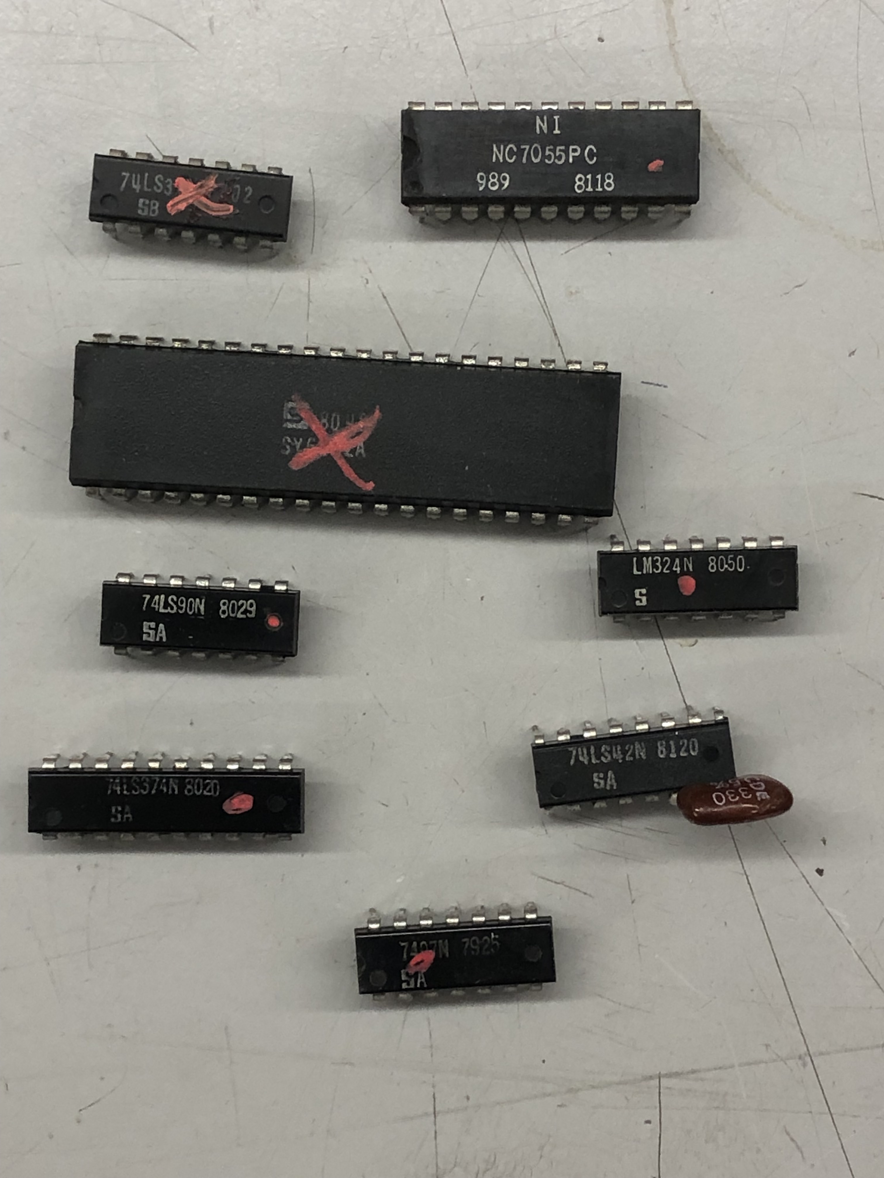
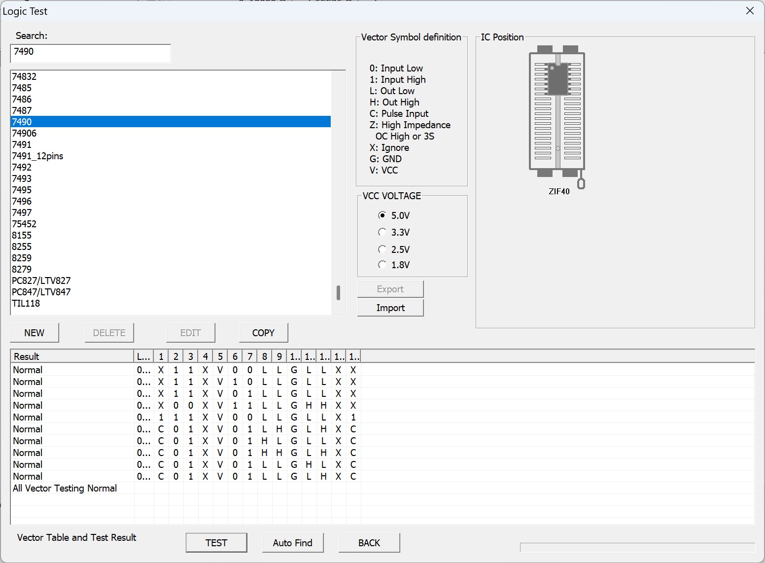
Ok.. my cheap Chinese chip tester can’t check the LS90.. But my T48/TL866 tester can check it..
Good 74LS90 and the bad one.. Partially working chip… verified..

Board works!
Board #16 – One of my boards
My plan was to offer it up as a swap for the board above. Now it will be offered up for sale.
I picked a nice board from by stash. Not surprisingly it was missing a Pokey. Connected it all up and it booted right up! However all of the motion objects were franticly jumping up and down as they progressed down the screen..

On Centipede – this is in the horizontal motion object section. Horizontal in this case is the long axis of the tube – which on Centipede is physically vertical since the tube is on its side.. can get confusing. Other games use X and Y axis based on the actual game orientation.. LS163@B5 was bad causing the bad motion object movement.
Once that was replaced – the trackball just wandered up and to the right.. Centipede test mode shows trackball movement as 1’s and 0’s.

The top 4 rows show the trackball X & Y movement. The bottom row shows the direction (I believe). In my case those bottom two 1’s and 0’s were not toggling.

Replacing the LS157@D/E11 restored full functionality.
Board works!
Board #17 – Board in for repair
Centipede sent in with Board 18. Game ran but had no horizontal trackball motion. Owner said this one was the CD40106@E/F10. It was. Replaced it.
Board works!
Board #18 – Board in for repair

Board was originally sold to the owner as working. Booted to this. The board had no life at this point . ROM and RAM visible to the CPU all checked bad. Removed the ROMs and still the RAM was bad.

Both RAM visible to the CPU were so bad that they took everything down with them. Replaced both RAM and the board booted again. All ROM were good. Once running.
No horizonal trackball – would it be the same as above? Bad CD40106@E/F11?…
No – Bad LS191@C11 – it is the counter that sends the motion back to the CPU.
Board works!
