
When I got my Star Wars – I was lucky enough to get a 100% original machine that a Star Wars fan had owned for nearly 20 years and rarely used. Everything in the cabinet was original with matching serial numbers. At some point the Amplifone boards had some work on them, but pretty minimal.
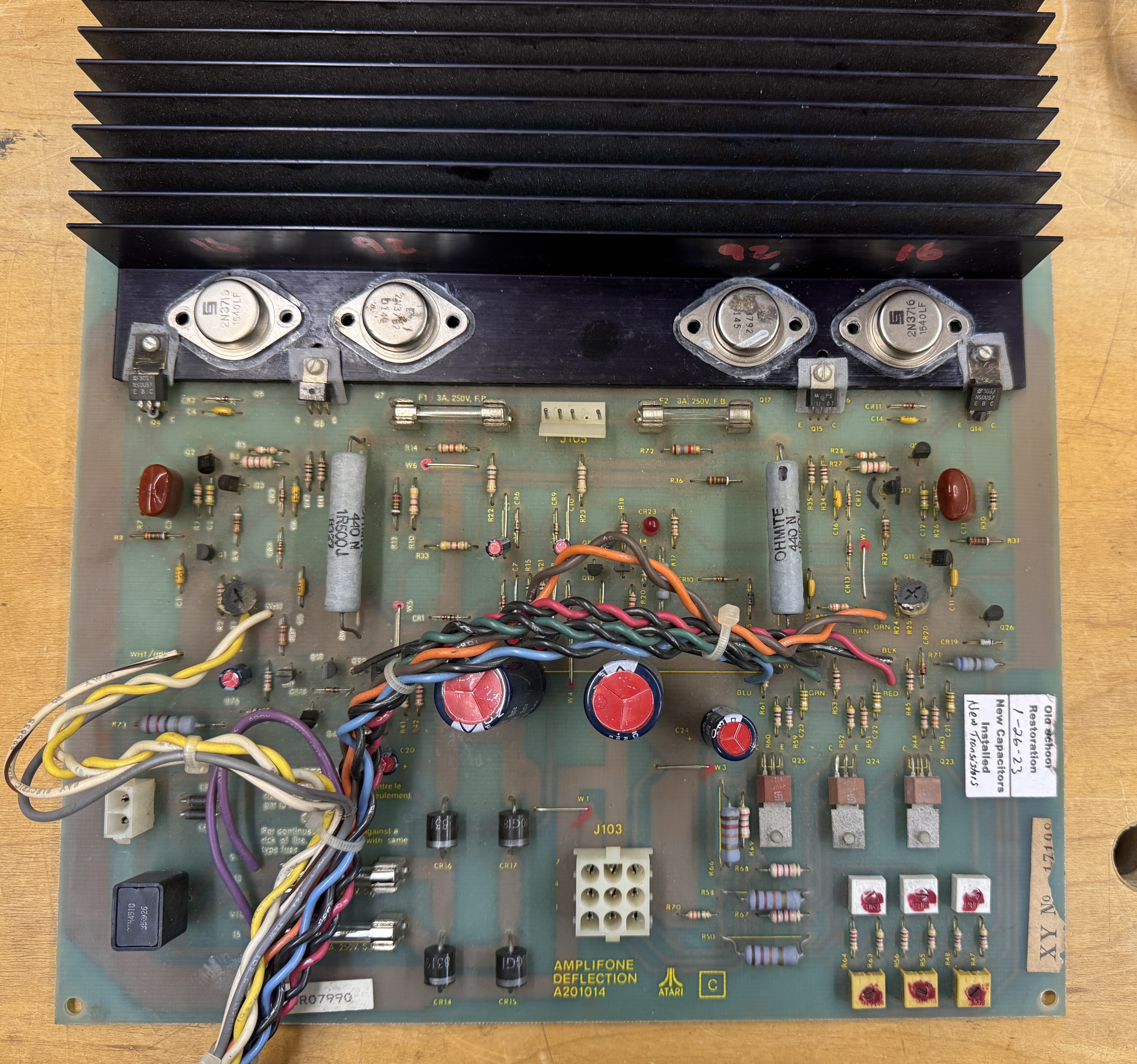
Mine started like this..

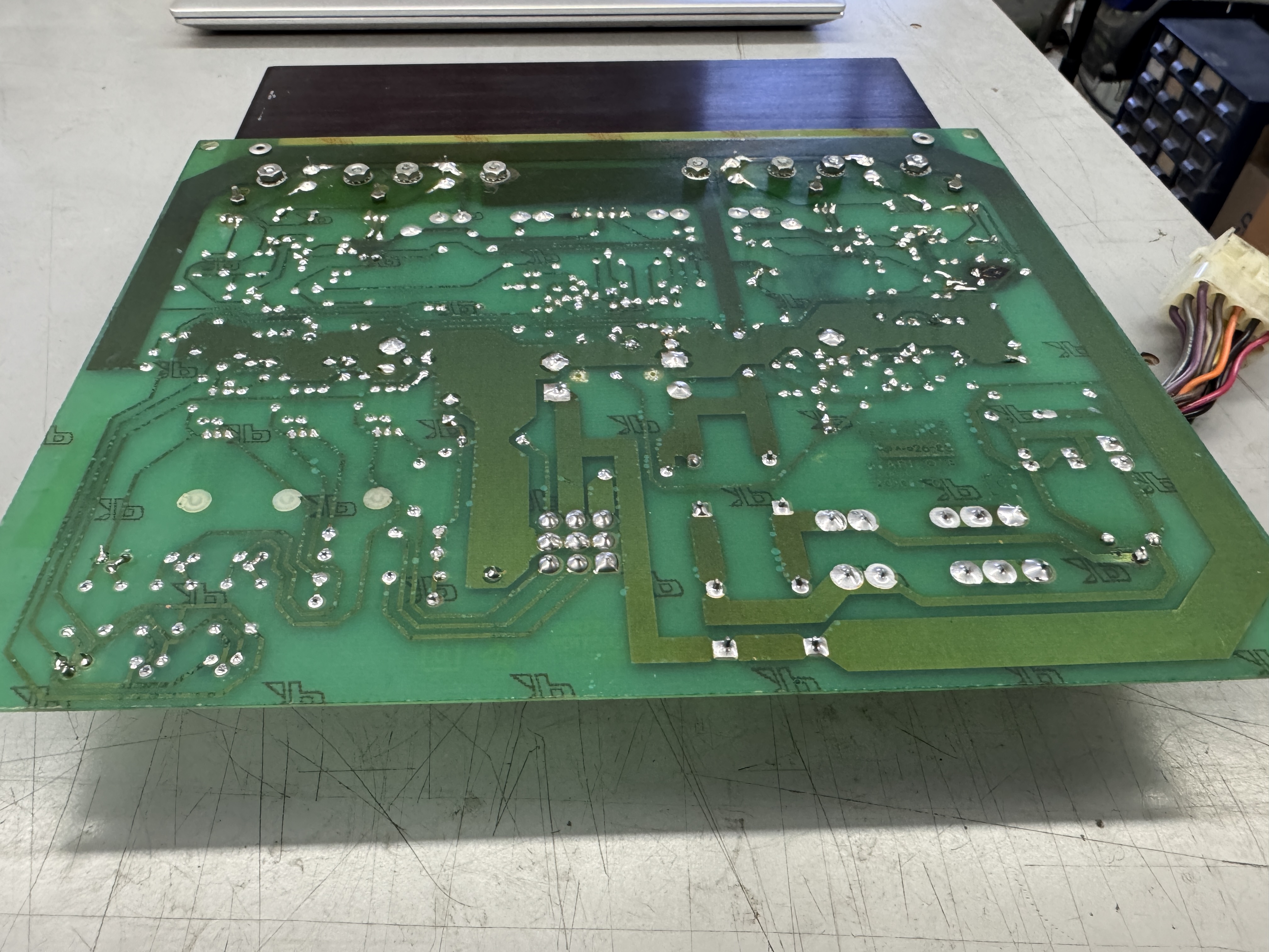
This board had been working fine – but needed some maintenance. I removed all the power transistors, cleaned out all of the thermal paste and replaced with Silpads. It had the original zero ohm resistors in the board. The FAQ was very clear – remove them all and replace with jumpers. It got recapped – mine were original.

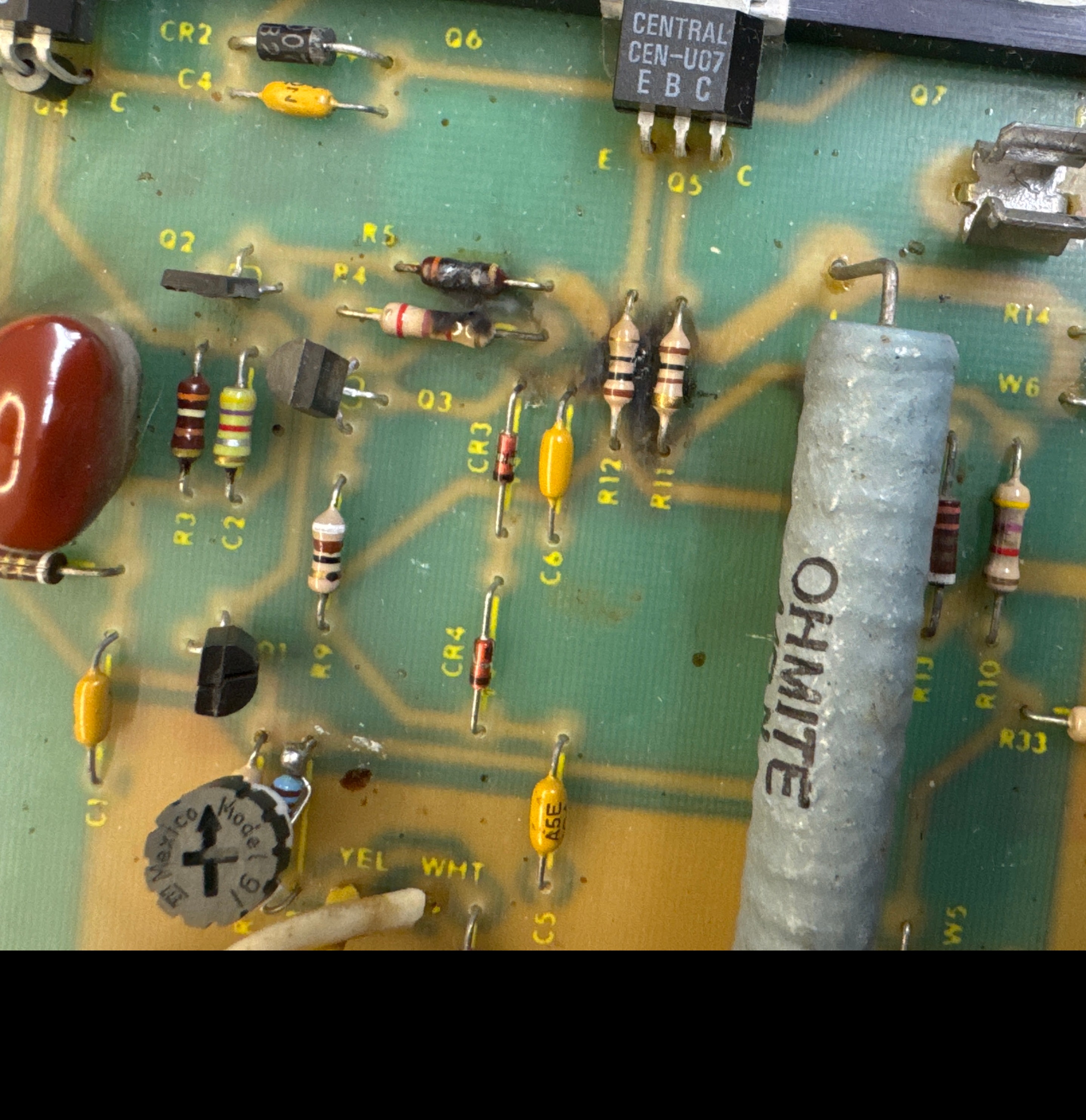
After some inspection – plenty of cold solder joints to reflow. I was not having issues due to these… but they obviously were coming.

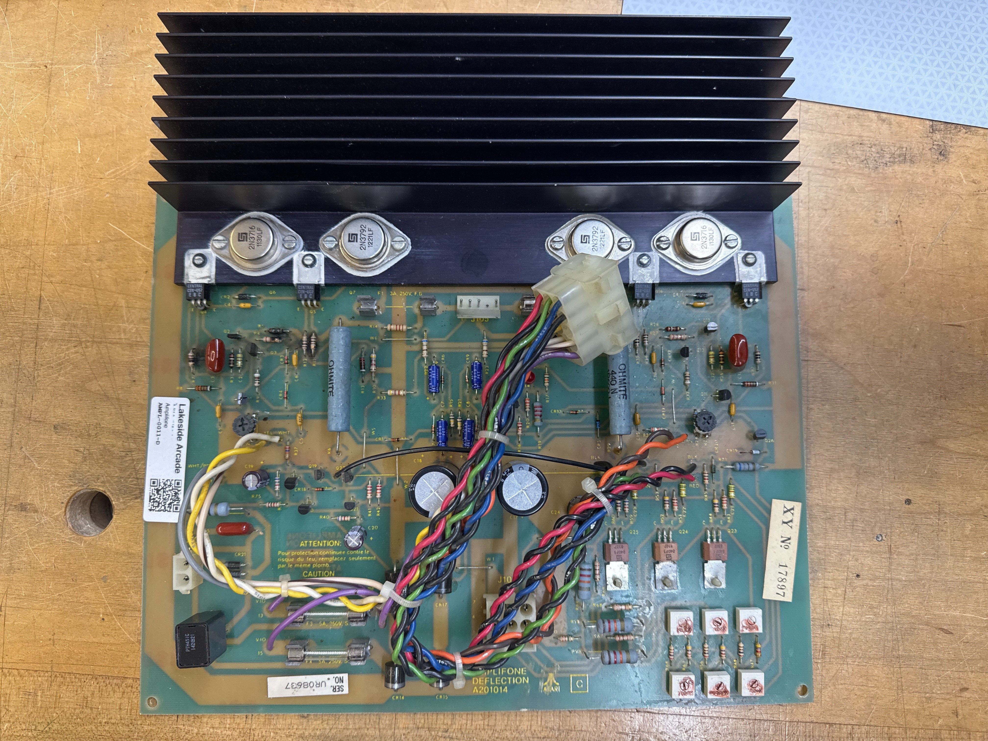
Completed. A really clean example of an Amplifone deflection board.
My game always had a blooming issue – most visible during the Death Star explosion, but I never looked into it. Turns out it was only getting to about 16K volts vs. the 19.5K it should be reaching.

I spent some time on this one.
First thing was R17 – the HV over voltage adjustment pot was just spinning freely – could it be that simple? No… I removed Q3 to disable the HV circuit and went through and tested the regulators and the frequency from the 555 timer and they all matched a known working HV. Some of the numbers did not agree with the Amplifone FAQ (7924 voltage was ~-31v, 555 frequency could vary from 22 khz – 26 khz).. The breakthrough was when I was messing around with Q3 to put it back… the heatsink started flopping around. Hidden cold solder joints… again.. The heatsink is also the contact for the collector on Q3. Reflowed that and now I could get the HV up to 20.5K.. I had also replaced ZD6.8V (@R16) thinking it may have contributed to the issue. I stopped working on trying to get the HV up to 25K for the protection circuit – but I did get my HV 19.5K for normal operation. Blooming problem solved.
Chassis works!
Amplifone #2 – In for repair


This one came in with a blown F4 and a bunch of mix/match caps. After recaping and a cleanup – I had to replace Q6, Q7, Q4. Q4 had a E<>C short.. Missed it the first time and blew fuse F1. I also replaced Q1, Q2, Q3 just because they are easy. After in-circuit testing diodes and power resistors, checking for cold solder and broken traces. CR2 tested bad in circuit – broke upon removal. The cover on the posistor which is part of the degauss circuit was missing. It works fine however.
Deflection works!

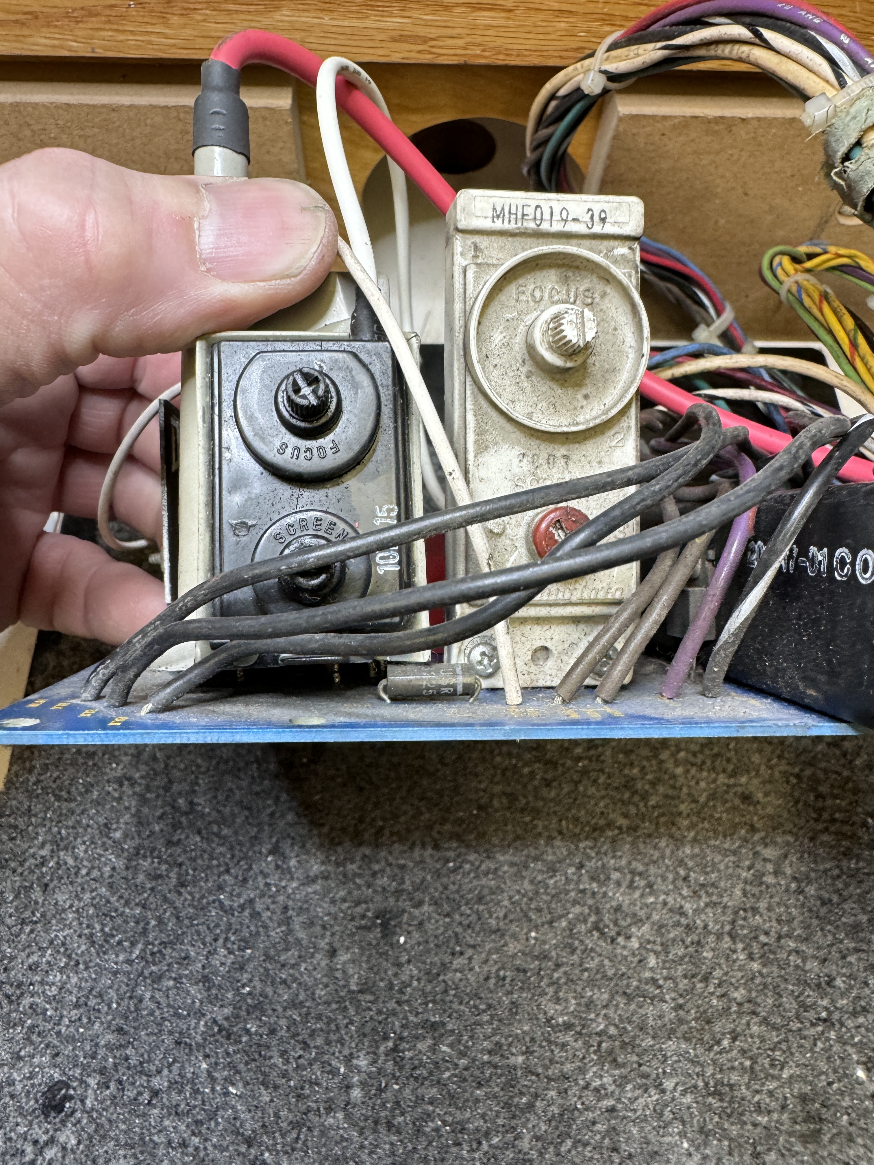
Once I connected up to the HV unit – no focus. Wire was broken inside the rubber boot.
Chassis works!
Amplifone #3 – Sent in to be ‘checked’
This one had incorrect 3A fuses (replaced with correct ones). I checked as much as you can in circuit. Once I connected it up – I have jumpy X vectors.
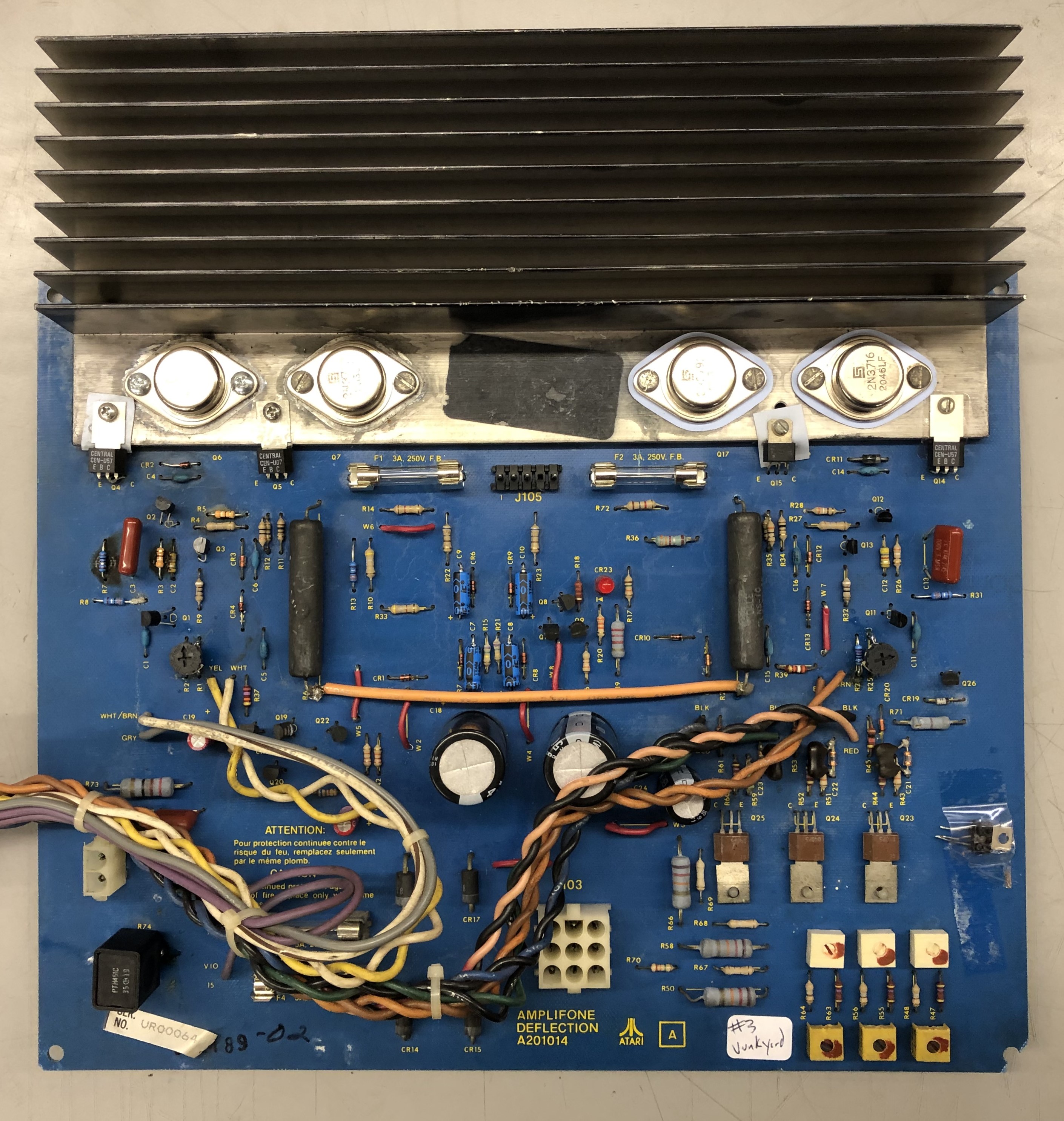
This one has a few miles on it..
Here are the jumpy X vectors
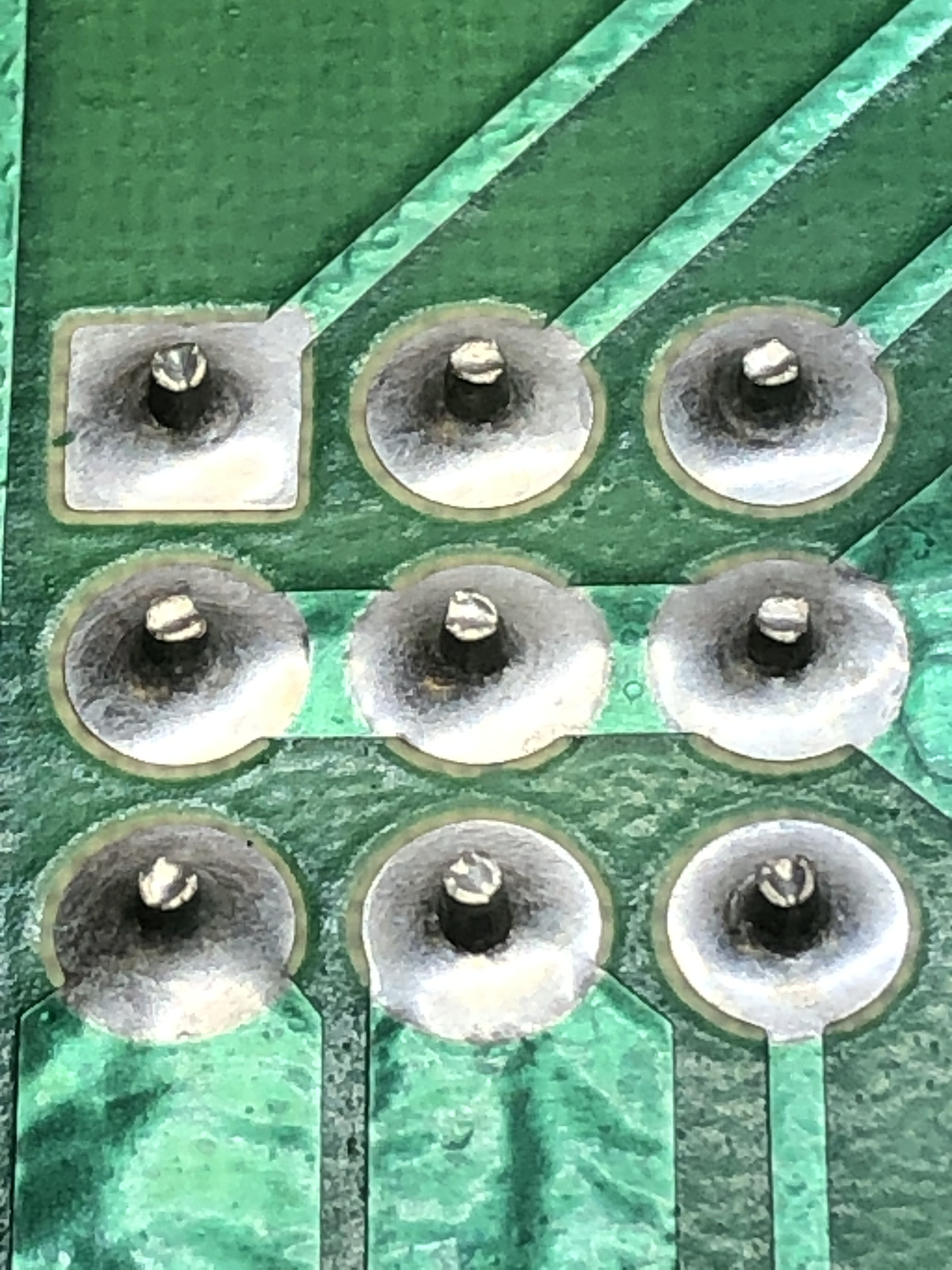
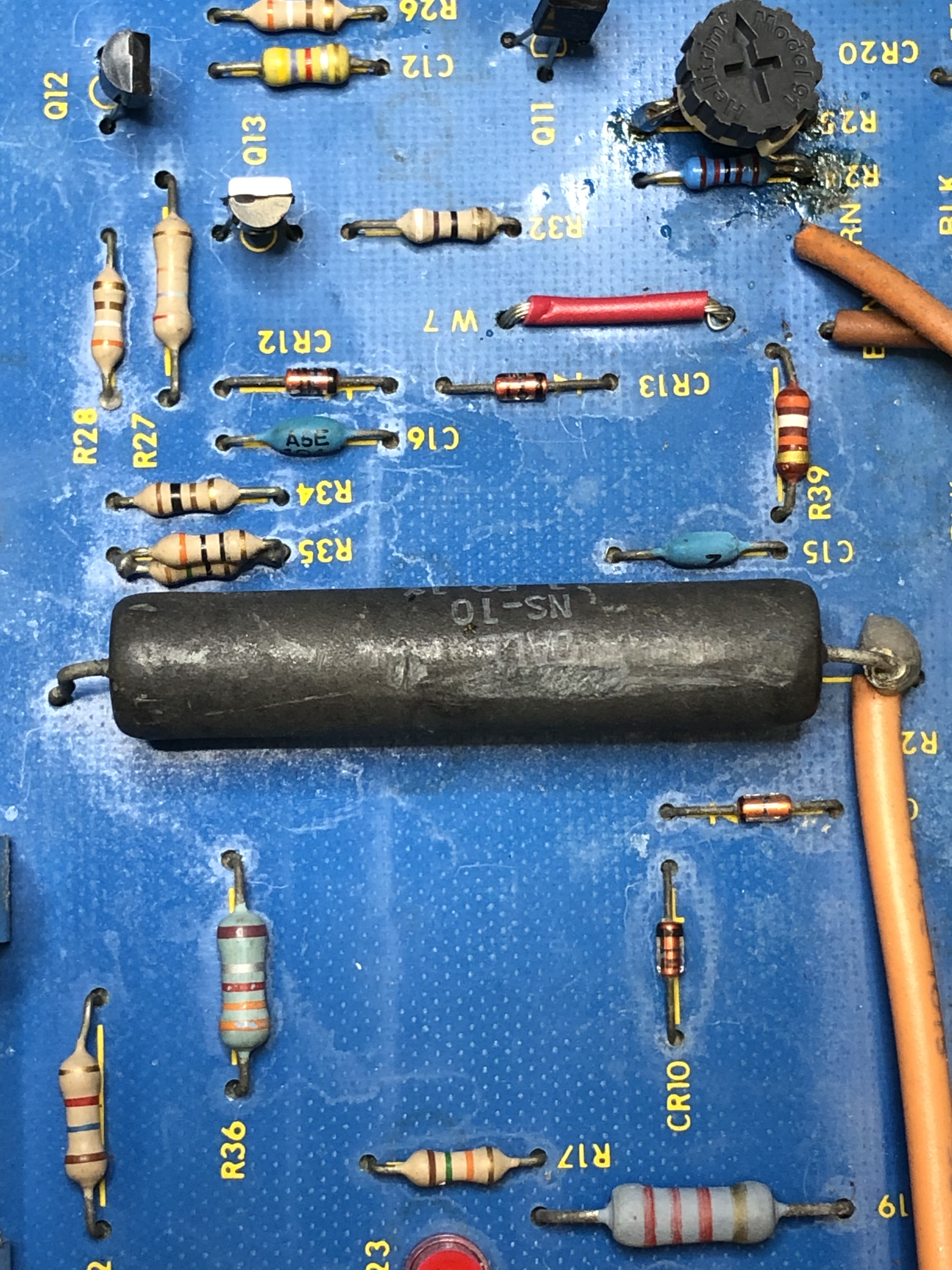
I spend some time trying to find the root cause – I Deoxit’d the X-pot, then swapped it for good measure. Looked for cold solder joints and even moved some transistors around. Flexing the board didn’t seem to do much. It was hit or miss. The symptoms kept suggesting cold solder or transistor drifting out of spec. After putting it in/out of the cab a number of times and pushing and pulling everything progressively more aggressively on the X side of the board.. moving the big power resistor finally revealed the issue. The cold solder joint on it was not visible prior to a little rough investigating.

I have a little more cleanup / maintenance to do..
Deflection board works!
Amplifone #4 – In for repair
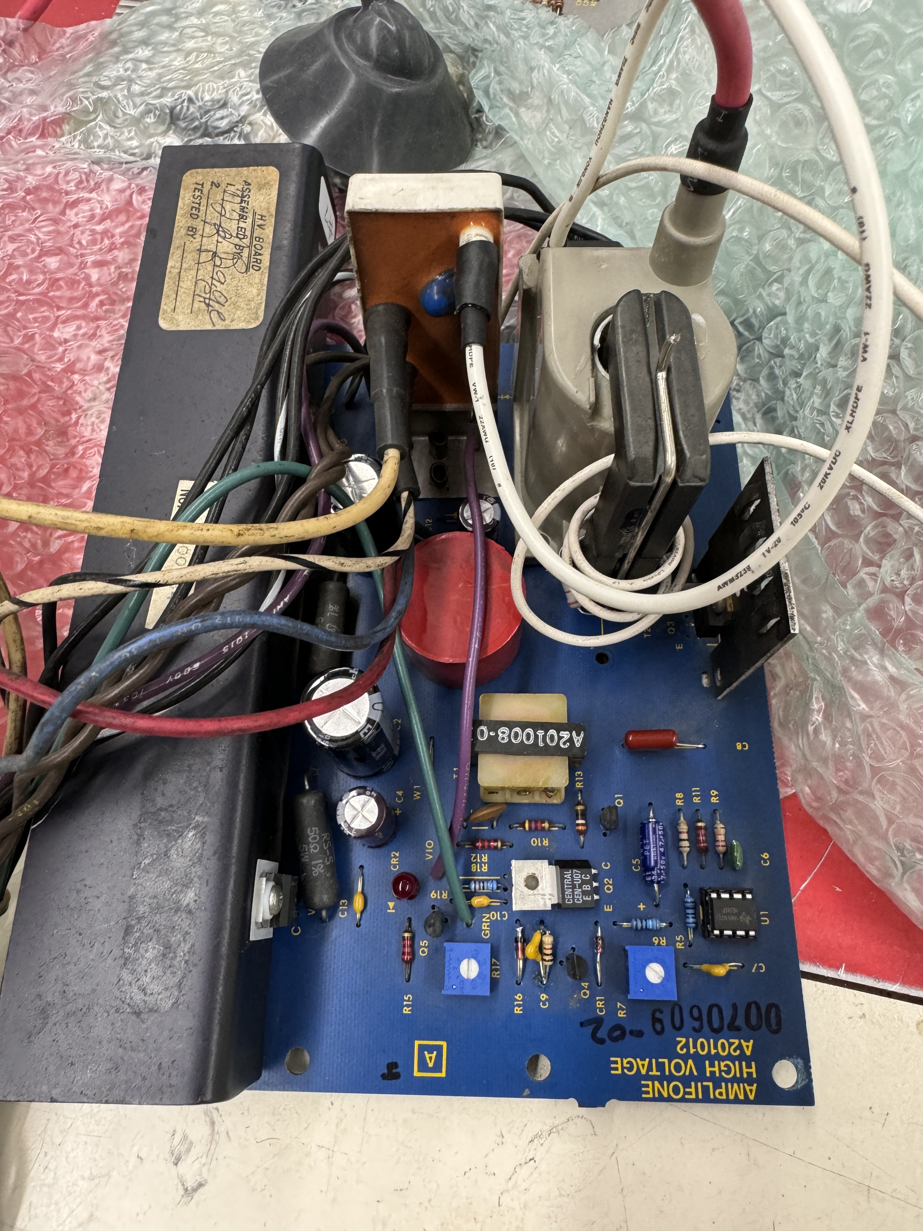
This one came in with reported poorly shaped vectors. After working though it, the HV was set to 21.5K and the brightness was turned down to compensate. The vectors looked terrible. HV adjustments fixed vectors. The deflection board had already been updated with all the MODs.
The HV board is special:
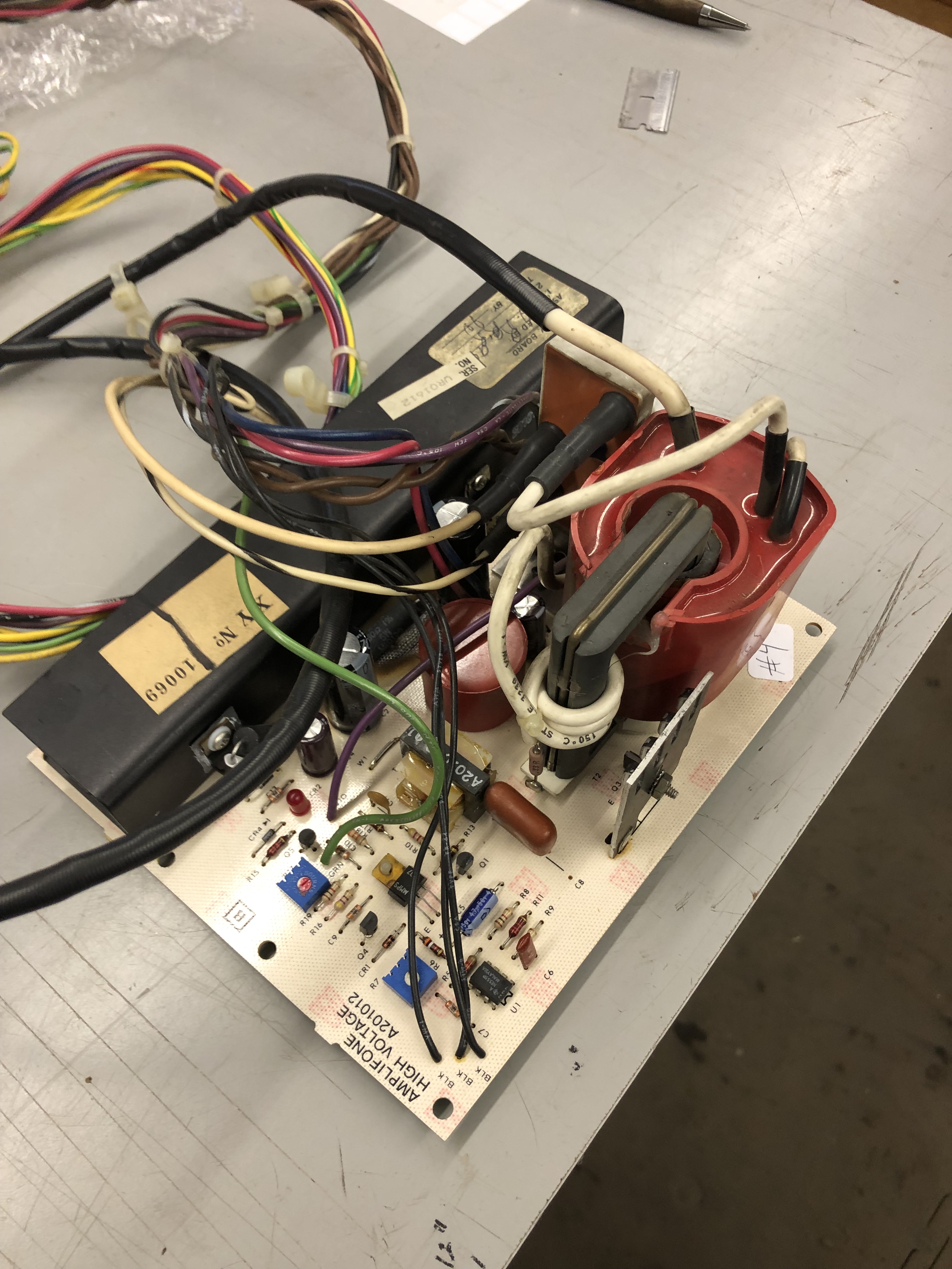
It has a very rare WORKING red HV transformer. The only mod I made was to remove the power transistors and mount replacements to the heat sink.

These are 50 ohm 30W resistors and easily mount to the heat sink. Much more heavy duty than the 50 ohm 5W originals that burn up frequently.
Chassis Works!
Amplifone #5 – In for repair
Had just got started on this one. Recapped this and the HV, cleaned up the power transistors and used silpads. Most of the X side was blown up. Thankfully it just blew fuse F4 vs. burning up.

Q14, Q16, Q17 and CR11 were bad. Replaced all the the zero ohm resistors. Did maintenance on the HV unit.
Chassis works!
Amplifone #6 – In for repair from one of my repeat customers


Symptom was chassis was blowing fuse F3. Interesting is the HV unit. I had not seen one of these before. Not 100% sure who made it. It didn’t need any work. I did notice that it takes significantly longer to show an image than my original HV unit. I measured 25 seconds before anything appears and 35 seconds to full brightness. Same deflection board with an original HV unit is ~14 seconds to full brightness. One more item I just learned the hard way.. This HV unit does not auto-discharge the tube. The original does. I got a little reminder pulling the anode cup off..
Items of interest:
- Replaced the zero ohm resistors.
- Recapped.
- Removed and cleaned all of the bottlecaps, replaced missing bolt. Diode tested.
- Replaced the adjustment pots. One was broken.
- Reflowed connectors.
- All transistors, diodes, etc. tested good in circuit.
I powered on in stages – just the degauss coil first – no fuses blown. Connected the yoke – no fuses blown. Connected the game board – no fuses blown – but the spot killer was either on or it blinked on/off. I connected to MY HV unit to see if I could get clues (Did not run it long this way, just long enough to see what is happening) First time through I had 1/2 horizontal collapse. The left side of the screen was missing. Replaced Q17.
Next power test the screen was WAY oversized and the spot killer was still blinking – also discovered R29 was getting burning hot very quickly – it was a transistor that was failing under load. I replaced all of the 2N3904s and the 5.1v Zener diode. No change. Finally replaced both Q14 and Q15 – both were failing under load.. Spot killer stopped blinking.

Chassis works!
Amplifone #7 – In for repair
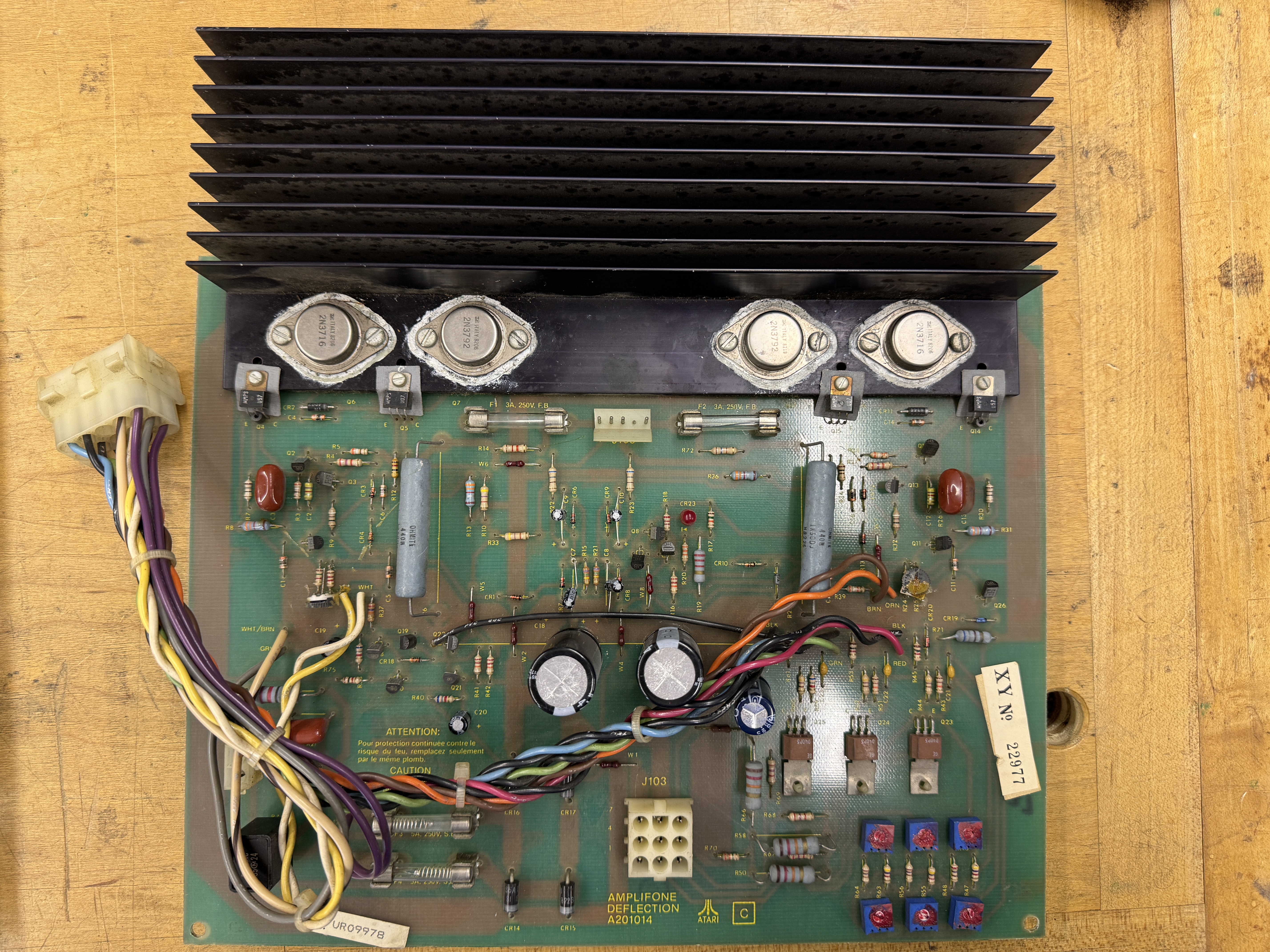
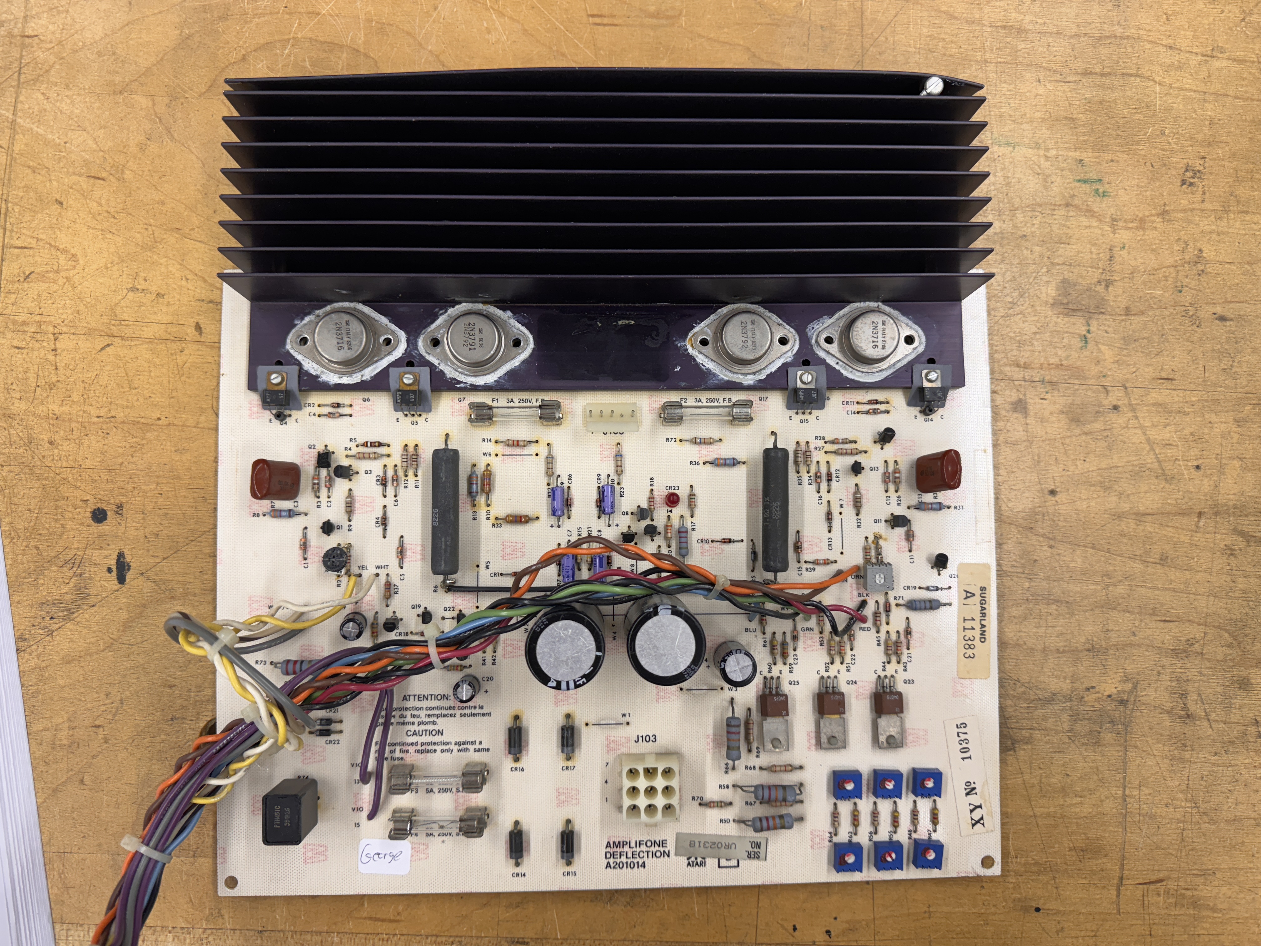
Here is where we started on the deflection board. It had all of the zero ohm resistors, but had been recapped at some point (with caps I don’t care for..) and it needed some general maintenance and cleanup.
At some point someone replaced the HV transformer – but they didn’t move this diode to the underside of the PCB so it is floating above the PCB? This got corrected.. Strange…
Once I got all of the maintenance work done on the deflection board – it ran fine. The primary reason it was sent in had to do with the high voltage board. Deflection will be more reliable.
The HV unit had a bad BU406D, I replaced the caps and did some initial testing. It also showed the 7924 voltage regulator as bad during power testing.. Replace that too. Once I got those replaced the HV started working as expected.. I ran the chassis for a few hours – no problem.
Part of my testing is to wait and power cycle the chassis a few times. Here is where this went of the rails. Randomly on power up, the unit would go into HV shutdown. The HV would jump up on the meter, then immediately shut off as if it was truly going to high.. Chasing this involved replacing many components and long testing cycles over the course of a couple weeks. I wanted to see if I could isolate the exact part that was borderline. Testing one part at a time would have taken months. Obvious components were the Zener diodes, I replaced the pots and a couple of the cermic and poly caps around the HV detection circuit. Then I could do 20-30 power cycles.. Some automated, some random and it would be fine. Then out of nowhere – it would shut down – bright red LED.. During these shutdowns the new 7924 regulator showed -31v across the terminals where it should have been -24 volts. I looked for shorted or failed parts – none.. Thee regulator was fine and would read normal voltages when it didn’t go into shutdown. I replaced a few more parts.
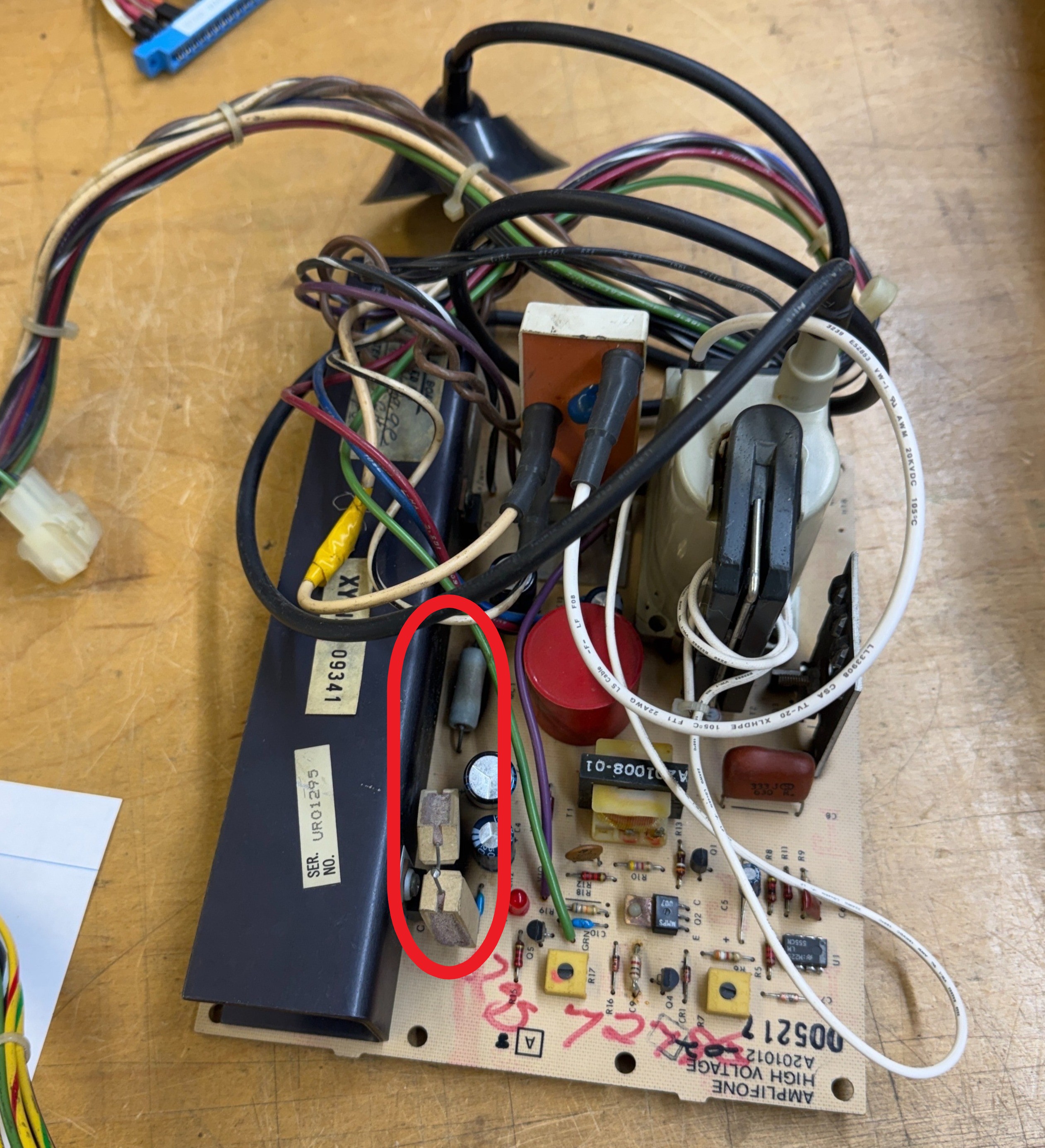
All that said – I believe the culprit was this 50 ohm wire wound shunt resistor that straddles the 7924. I can’t be 1000% sure because I have no way of testing for it.

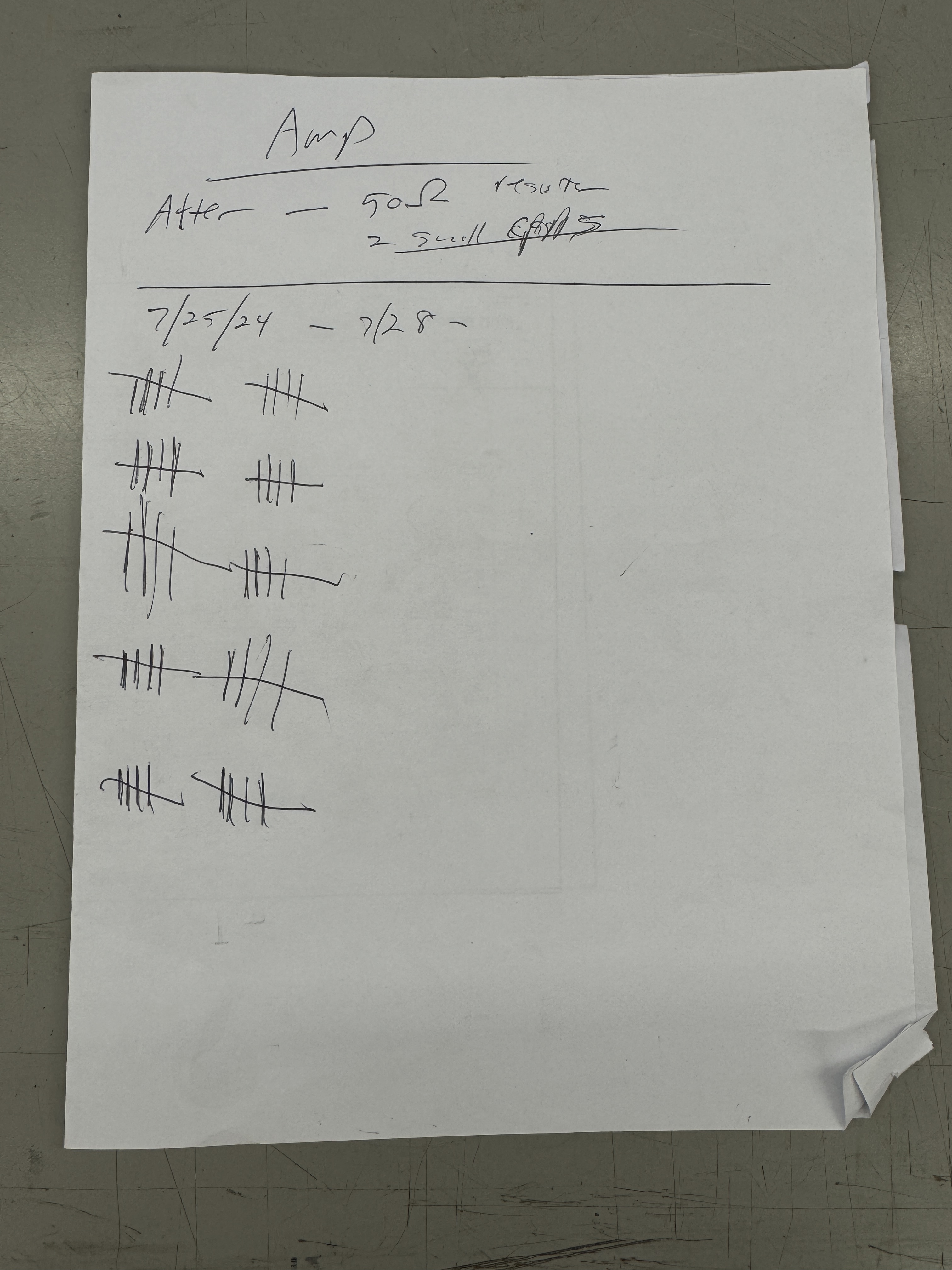
It tests fine – but I think it is randomly breaking down/shorting internally causing -31v across the 7924 over powering the HV circuit and causing the shutdown. Here are the last 50 power cycle tests where there was no issue. I’ve power cycled this chassis over 200 times trying to determine the root cause. My automated smart outlet turned on my Star Wars cabinet for 10 minutes, then off for 10 minutes. I would check these off while working on PCB repairs over the course of a couple days.

Before & after. This one put up a good fight.
Chassis works!
Amplifone #8 – Deflection only – In for repair
I forgot to take a ‘before’ pic. This one is after it was completed.
Here it is completed, but it put up a pretty good fight. Came in with F1 blown and reported not working. It had been recapped in the past and is a spare. Sat on the shelf for years and then needed to be used.
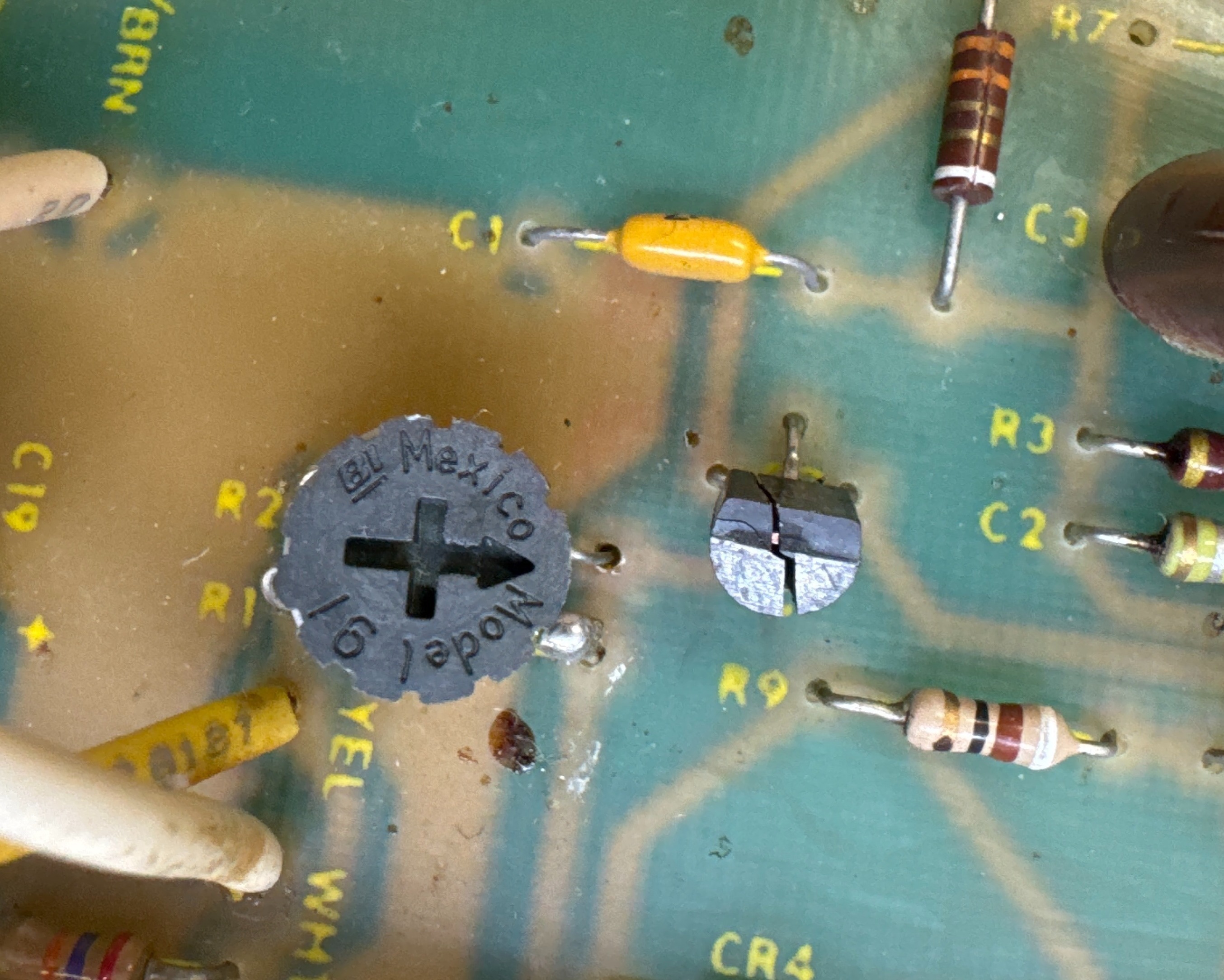
Initial triage was Bad F1, CR5 burned up and I discovered a cold solder joint on R29.. The large black wire wound resistor. I’ve seen this a number of times now. Often not visible, but wiggle it a bit and it will break loose..


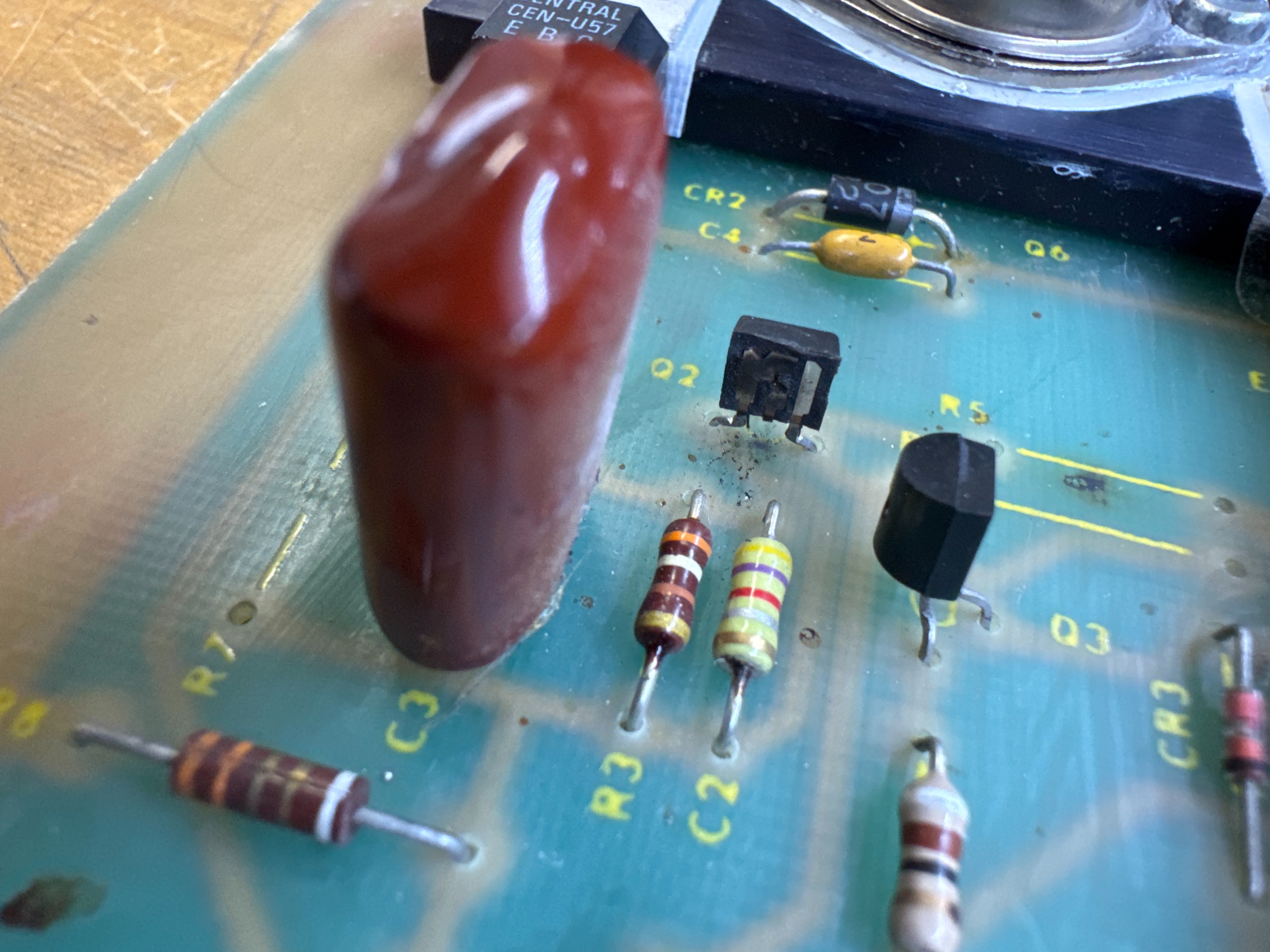
Here is how that joint started. CR5 was charred and the transistors with their legs crossed were put in to replace the CEN-U57’s that are screwed to the heatsink. They were BD139’s and are supposed to be able to replace the CEN-U57s. I didn’t dig into them to see if they were connected correctly initially. I’ll have to do some additional research on these since the CEN-U57 are no longer made and have become very expensive.
Another item were the bottlecaps had been replaced at some point. Not the standard part numbers.
Cross referenced:
- 2N3716 – 2N5883G – MJ15003G
- 2N3792 – 2N5884G – MJ15004G
These can be substituted for each other. I recommend they are done all in the same model line however.
After making all of my usual checks and replacing a few parts, boom! A 2N3904 popped. Could not find a shorted component, but it took a few others with it and a resistor fried. Replaced all of that and popped a different one. At this point it seemed like it had a transistor or diode failing under load. This one put up a good fight and took most of a day to work out all the kinks.
Replaced both CEN-U57s and CEN-U07’s plus rechecking the other components. Ran for 3+ hours w/o issue from here.
Chassis works!
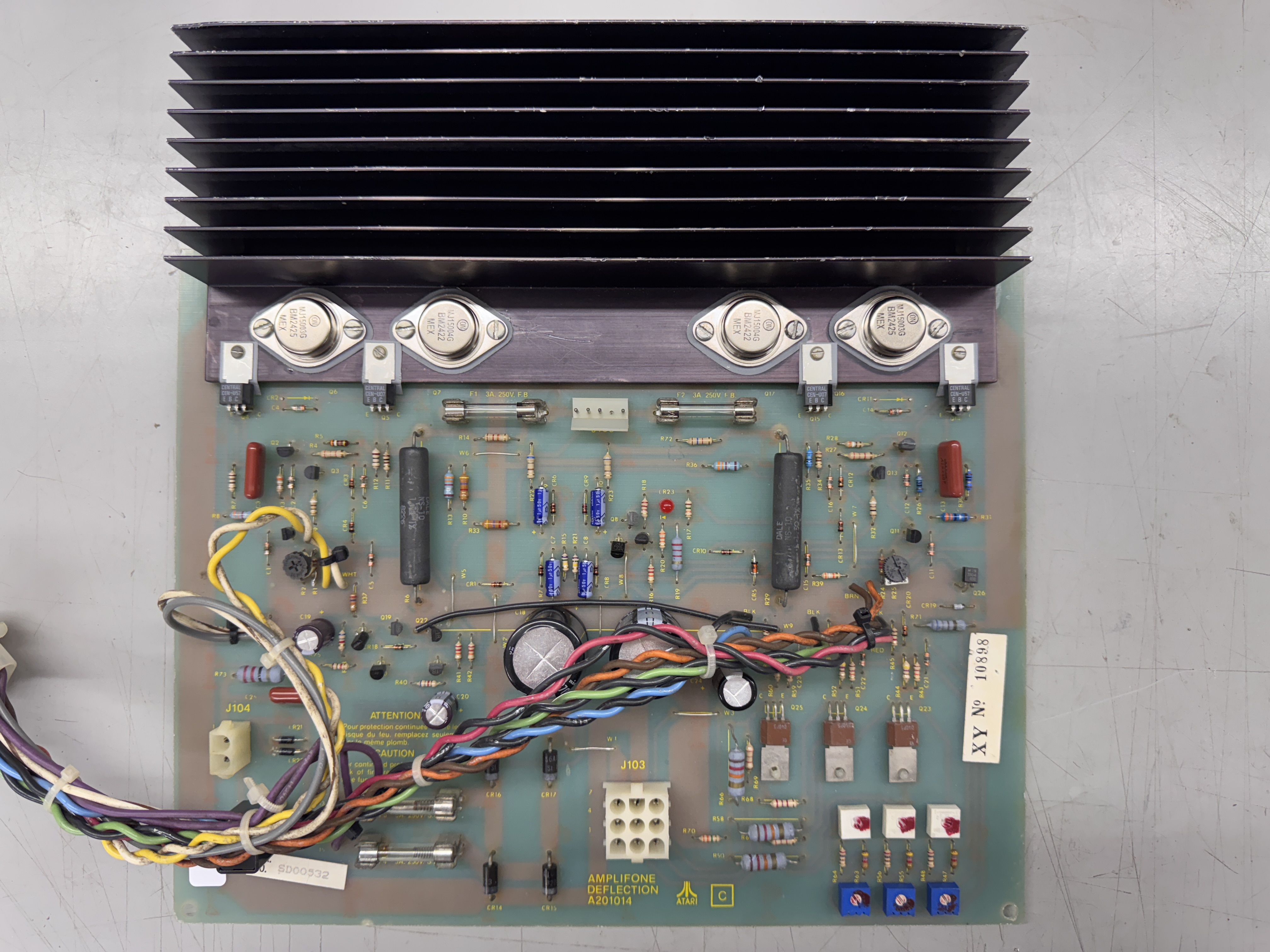
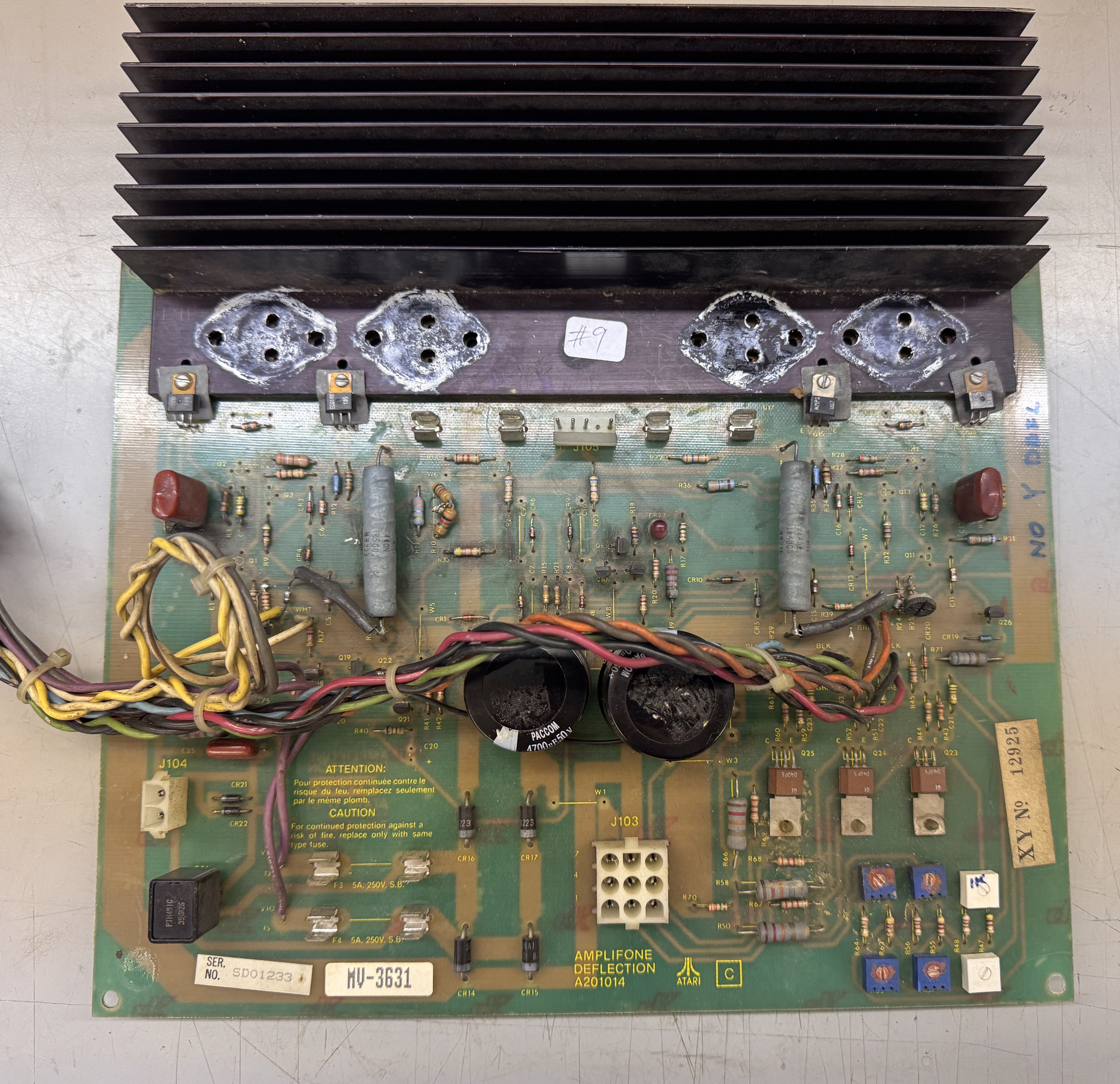
Amplifone #9 – Deflection only – In for repair
This one came in with a Star Wars set. Asked to get SW and this working again.
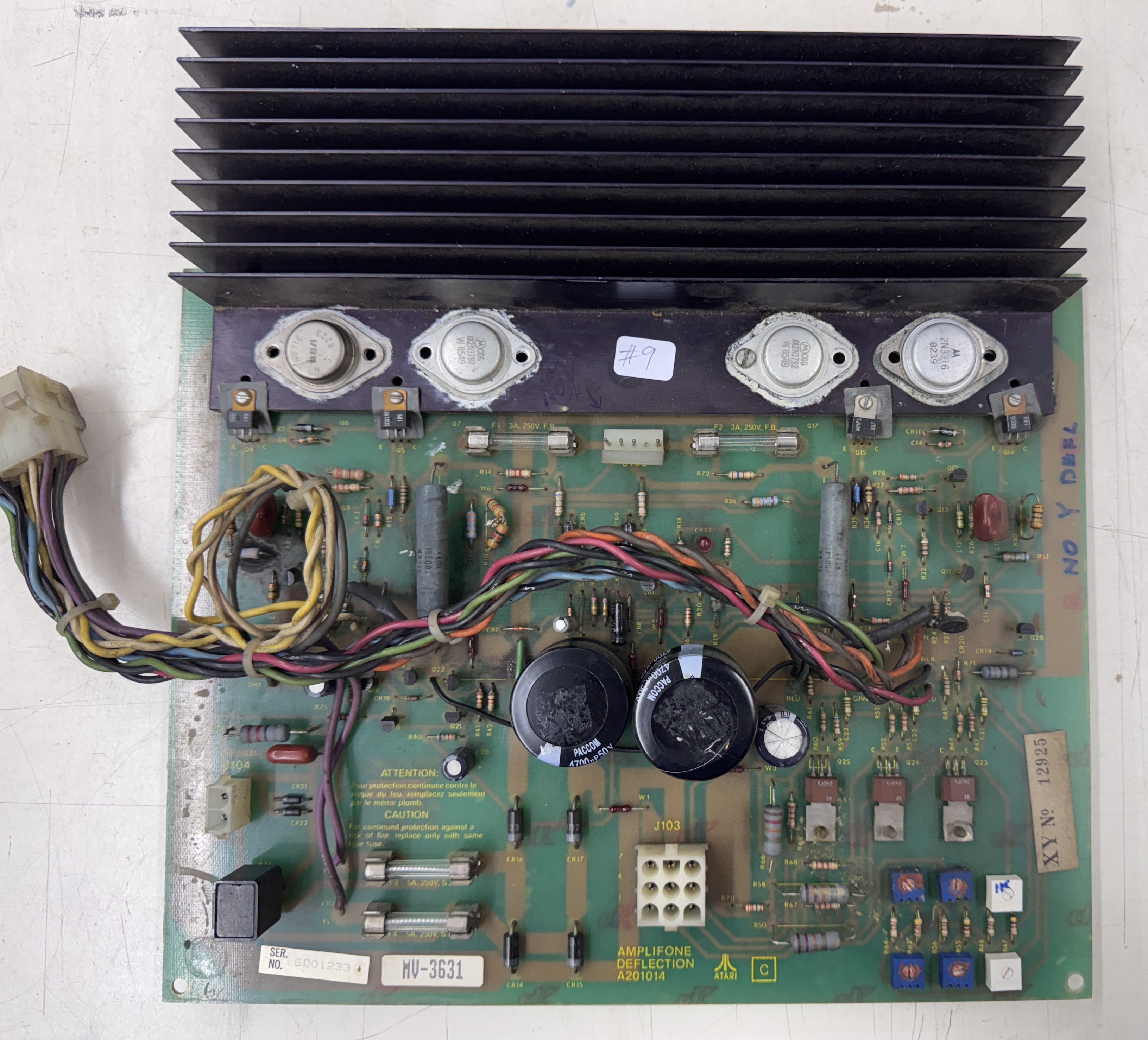
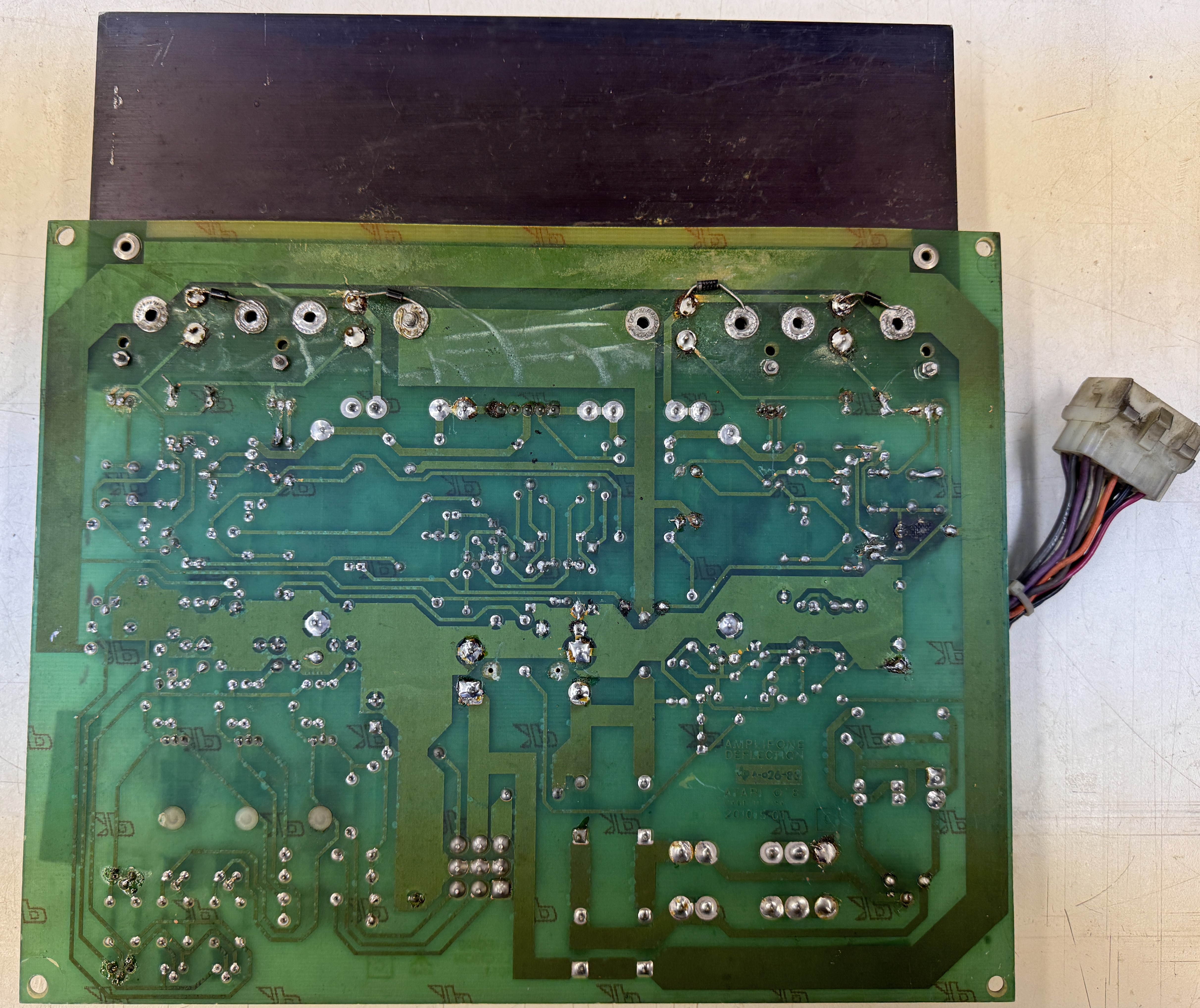
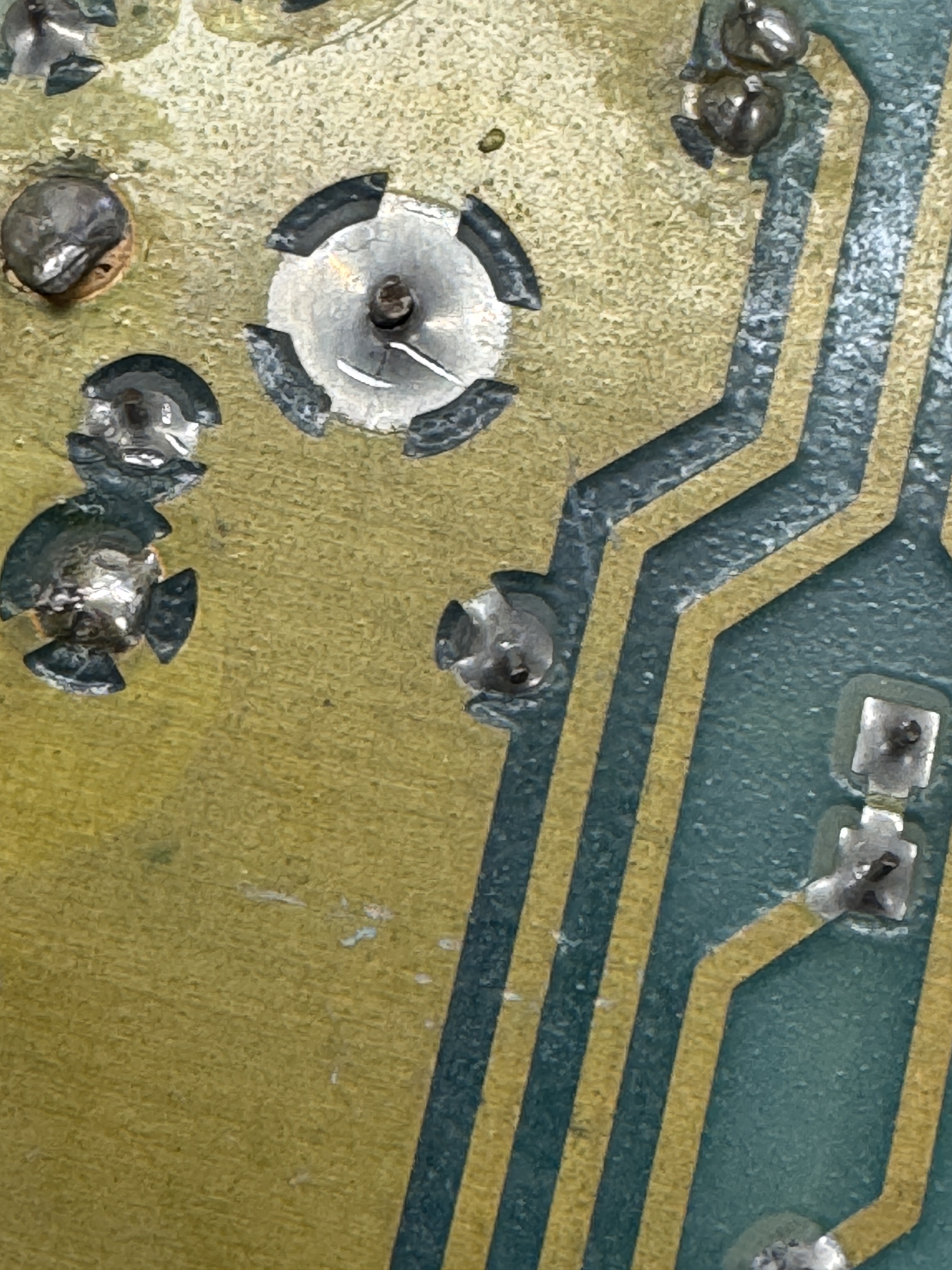
I had just got the screws out and then I remembered to take a ‘before’ pic. This one has a lot going on.. Prior burned spots, all of the zero ohm resistors are still on the board. It was dirtier than it looks. Seemed like the original caps, except for the filter caps which had been replaced at some point. There was lots of prior work and many of the traces on the backside had damage. Difficult to see all of it in this pic.
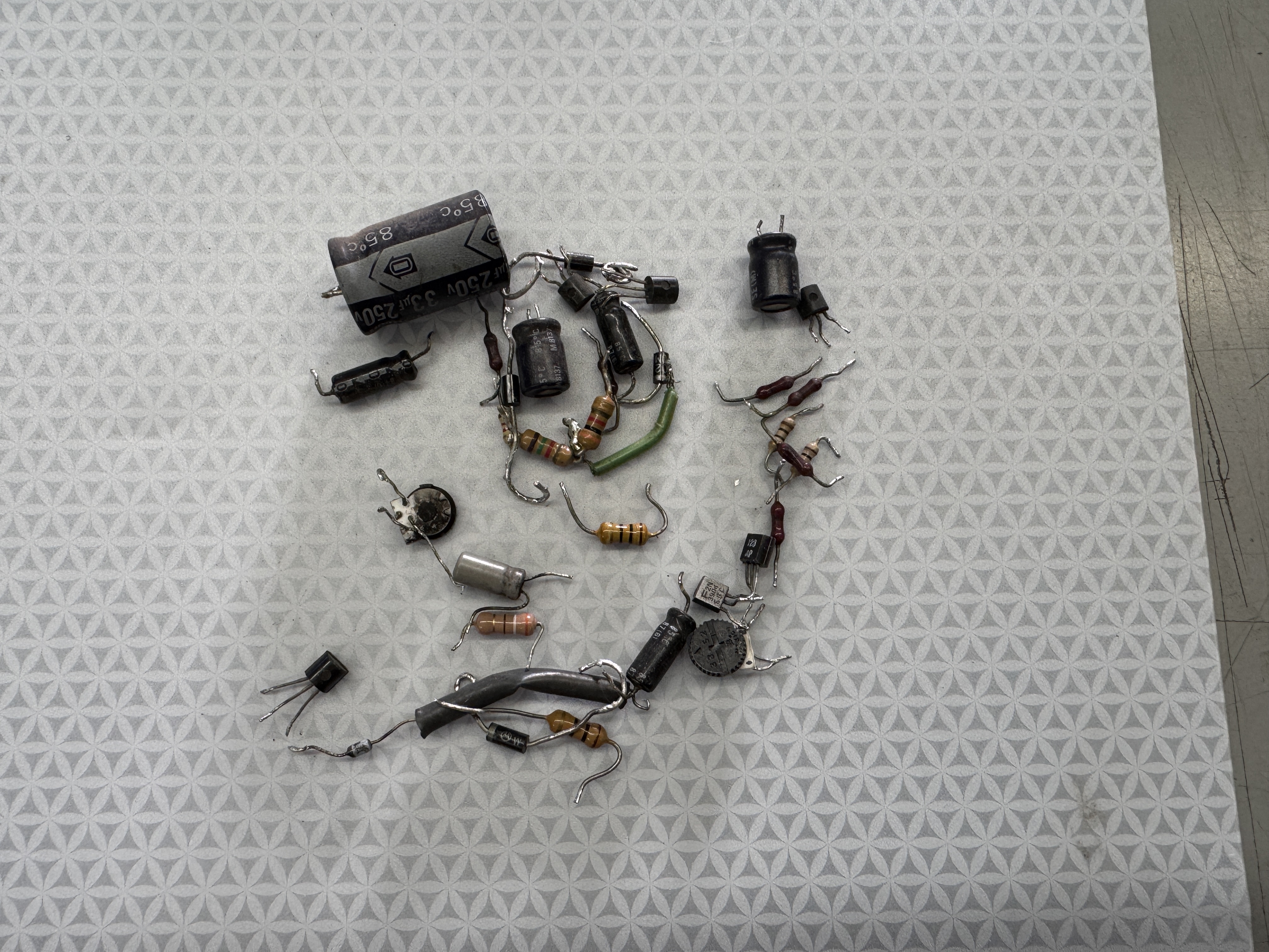
Here it is stripped of most of the components. I checked a few resistors that had been replaced at some point with new ones that were over wattage on the specs. They got put back to their original sizes.
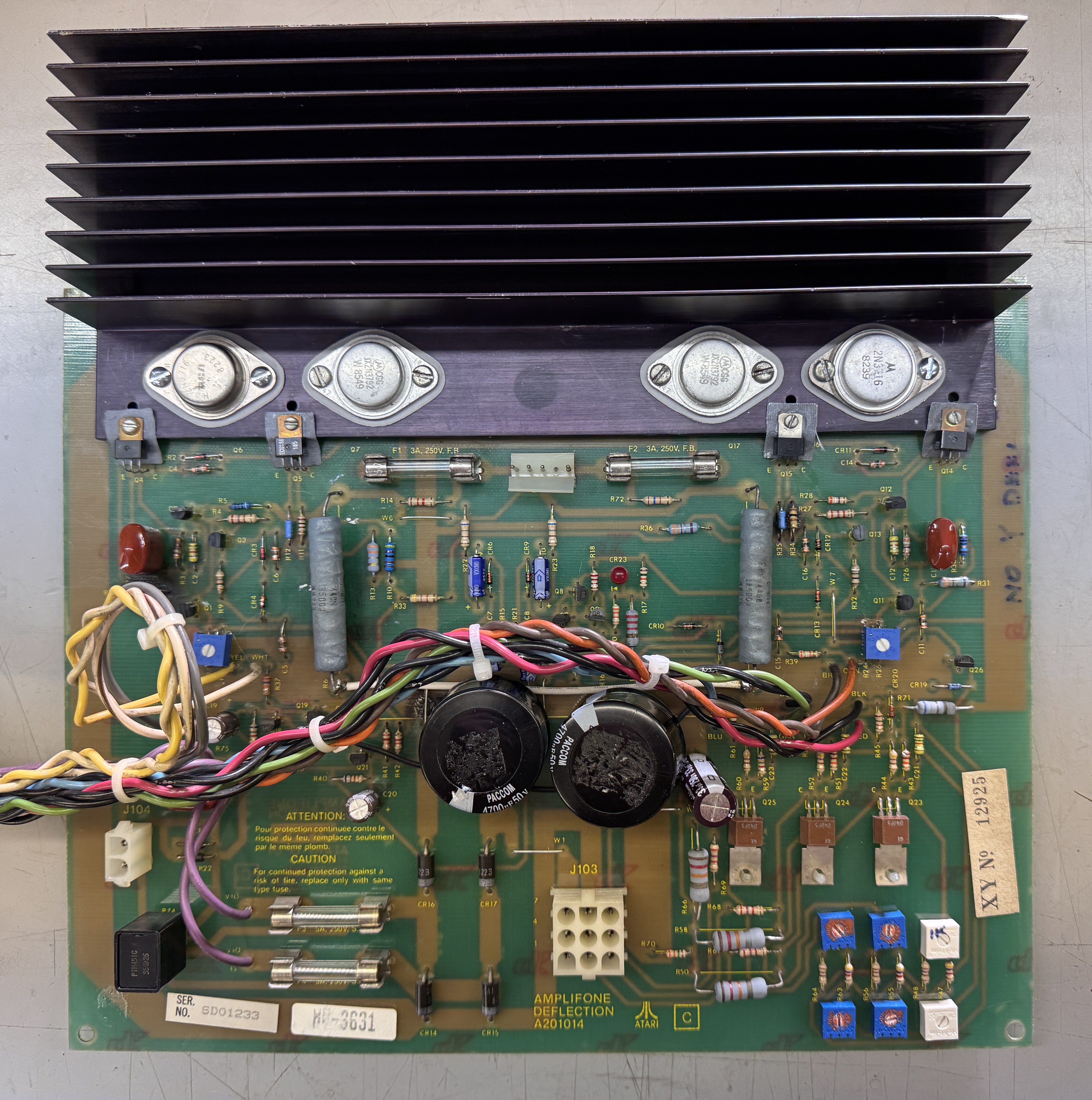
Cleaned up, replaced the caps and corrected a few issues, replaced components from my ‘always replace list’. One of those items is the X/Y adjustment pots. The originals need to go as they introduce jitters more often than not. Three of the wires easily had broken free from the PCB. Spent some time reinforcing damaged traces on the bottom of the PCB too.. Took a few hours to get this all corrected. But once it was completed..
Chassis Works!
Amplifone #10 – In for repair
This one came with Star Wars boards, an ARII and the Amplifone. Star Wars was down. Labels showed it had been worked on in 2023. The ARII had serious issues. It was putting out 7V (got that repaired). The Star Wars PCB set was fine thankfully. The Amplifone deflection board worked, but the HV did not.

The deflection board was ok. It got recapped with ‘Ritchy’ caps? Never heard of them. One of the fuses was wrong and there were a few items I wanted to upgrade. The HV board had the wrong caps @C1, C2. They were 100uf 50v vs. 470uf 50v. Probably did not cause the failure, but after checking with the owner – he wanted it made as reliable as possible. This work had been done in 2023.
The HV transformer had been replaced at the same time. When testing the HV unit – it would start up and then go into immediate HV shutdown. I spent some time checking all the components. Replaced the BU406D (it was shorted/failed). After recapping and checking lots of parts, I swapped in a new HV transformer. HV unit started working. Unfortunately they are just not very reliable.
After that I replaced all the caps on the deflection board, rebedded the bottlecaps with Silpads, replaced the adjustment pots with sealed units plus some other items.

Once this was all done.
Chassis works!
Amplifone #11 – In for repair
Been rebuilt at some point, no caps needed. I’ve seen mostly Y side blowups on these. Clearly it works harder than the X.
– Q4 Shorted all 3 legs – Unusual
– Q6 Open all 3 legs – Very Unusual!
There were some very healthy explosions when this one failed
Replaced 50 ohm resistors on the HV unit – the ones there were semi-hacked into place.
Chassis works!

Great work Bob thank you for bringing my deflection board back to life. I am so happy with your service and fast turn around.
David
Ontario , Canada
Bob,
I am so grateful to you for bringing back my Amplifone Star Wars back to life!!!!! You really are offering a great service to everyone in the Arcade community, and we appreciate you greatly!
Matt
Iowa