
Board #1 – My Personal set
I accidentally happened across an original Red Baron board set. Overall it is in very good shape. I performed some basic maintenance to it and corrected a few issues.


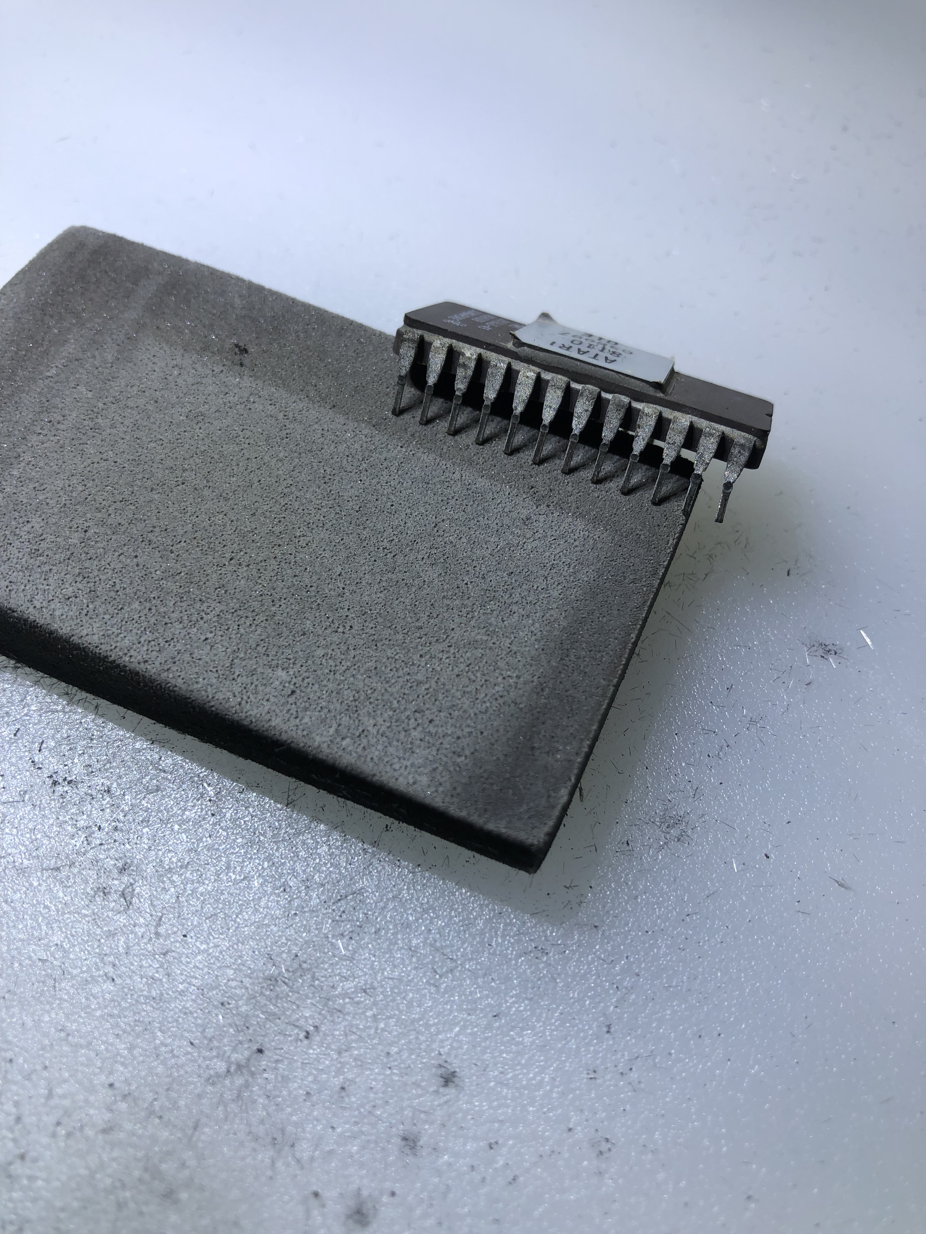
Cold solder joints on the interconnect, the edge connector was really chewed up and the chip legs were all pretty dirty/oxidized. I worked through the stack and corrected these. Board started working. I haven’t done much with it until I pulled it out to use as a reference for Board #2 below. While using it – the EPROM 036999 failed and corrupted the EPROM bus on the right side. I had to stop and figure that out. It has bad EPROM sockets too, had to reseat a few times, but that is a future me problem.
Board #2 – Board in for repair

This is basically identical to my RB set – there are two board revisions for Red Baron. The ‘redbarona’ revision – which is the dedicated Red Baron set. The CPU board has 7 EPROMs on the right and the AUX board has an extra PROM. The ‘redbaron’ revised hardware version uses a modified Battlezone board set (is my understanding) – It only has 6 EPROMS on the right.
Once all of the board maintenance and cleanup was completed – I connected to the FPGA tester. RAM @C2, B2, B1 all checked bad. Socketed and replaced them. RAM & ROM now checked good.
Using the FPGA tester to test the vector generator, the HALT and draw single short tests seemed to be working. JMP seemed to work. VG Center would not run and timed out. I had set ‘Reset after Test’ to allow it to loop while looking for the problem.

It took a little hunting to find the issue. Here in the Vector Timer – LS161@N6 was doing bad things which confused the issue. A 12 MHz clock enters the chip on Pin2, however this chip decided to reroute it through the counters and output 6 MHz on Pin14, 3MHz on Pin13 and 1.5MHz on Pin12. Replacing it got VG Center running correctly and all of the other tests running in ‘normal looking’ timings and I no longer needed ‘Reset after Test’ set, progress!
However – not all of the tests had the correct timing. The remaining LS161’s all checked good.

At this point the VG Draw from Ram test – my personal favorite – had incorrect timing at around 6000us vs. 1174us. Also no activity on the scope. This test draws a Battlezone gunsight. If you see it – you usually have a fully functional vector generator and working analog section. The issues with this part of the board were also sequential in nature. Had to get the timer running to get the shifters loaded correctly to get them running. In this case, LS194@B5 Pin 14 had no output. Replaced it and the full VG works! Nice Battlezone gunsight on the scope. More often than not, everything works at this point.
This time we had a NOT..
Disconnected all the testers, powered on the board, DIAG mode would not run. Board crashed and reset. On the DIAG screen? Went back, rechecked all RAM, ROM, VG – all 100%. This one had me thinking for a while – I went and checked all around the watchdog circuit, everything seemed ok. I was considering some sort of decoding/addressing issue that the tester doesn’t see because of the nature of testing one part at a time.. But could not find anything jumping out.
Finally I looked at the VG Address Selector

LS157@H4 was the offending chip. Another partially (and correctly) working chip. The CPU could address RAM and ROM correctly – which comes through the 157s. The VG on the AVG side could not, and that was causing the crashing in DIAG mode. Once this was corrected..

The DIAG screen would boot, but the crosshatch was scrambled. Going back through the LS194 shifters. A5 was was bad. Replacing it fixed the crosshatch too. Finally something I could put on a tube. Now that I could see DIAG mode, the AUX board showed a ‘L’ error. Had to replace a bitslicer.

Board worked.. for a few hours. I burn in boards with the scope attached. Everything was good there.. Connected it to the monitor and no Z output.

Replaced the LS164@P9 to restore the Z.
Board works!
A few observations from this one and over the past couple years. Anecdotally, when a TI chip fails.. it generally does it with the outputs getting pinned low or high or floating.. Signetics chips can fail the same way, but a significant portion of the time, they fail by outputting bad data. Clocks being rerouted internally or partially working. They just tend to die in a much more difficult way to diagnose on occasion. Every dead chip on this set was Signetics. Another item is boards that have sat unpowered for 20-30 years tend to have a LOT of dead components. I checked with the owner and he told me he got it from someone who had it on a shelf. I did a Star Wars recently – same thing. Stack had to be sitting for well over 20 years with a lot of failed chips. Both didn’t come from a working machine.
To run this set on the bench – I used my Battlezone bench adapter. BZ was the first board I ever worked on – on the bench and it’s bench harness was the first I ever built up. It was a huge one-off setup. It was made long before I created my current adapter system. It got ‘backported’ once my current setup was developed. Prior to that I was curled up behind cabinets working on milk crates. It’s still a bit clunky compared to my newer adapters – but it works. That said – BZ and RB are nearly identical from a pinout POV. All the power is about the same. Without too many changes I could make my adapter work for both. The pinout diagrams available for both were opposite of each other (i.e. the columns were backwards) and RB was incomplete.

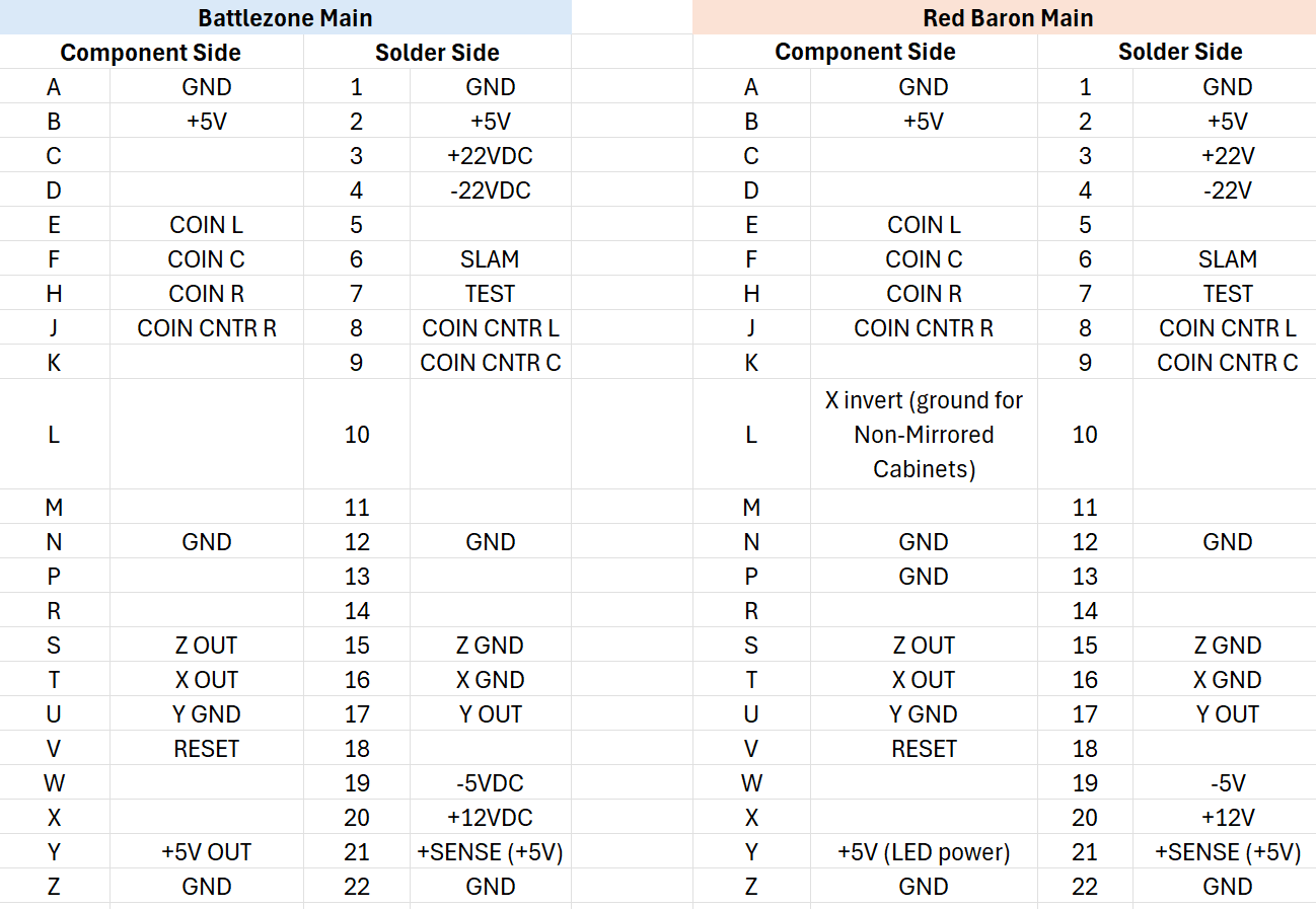
I had to reformat and update pinout charts to be able to read them to modify my harness to support Red Baron. This is for the redbarona boardset. I do not have a redbaron (Battlezone modified) set to double check this pinout. Maybe I’ll get one of those to repair down the line.


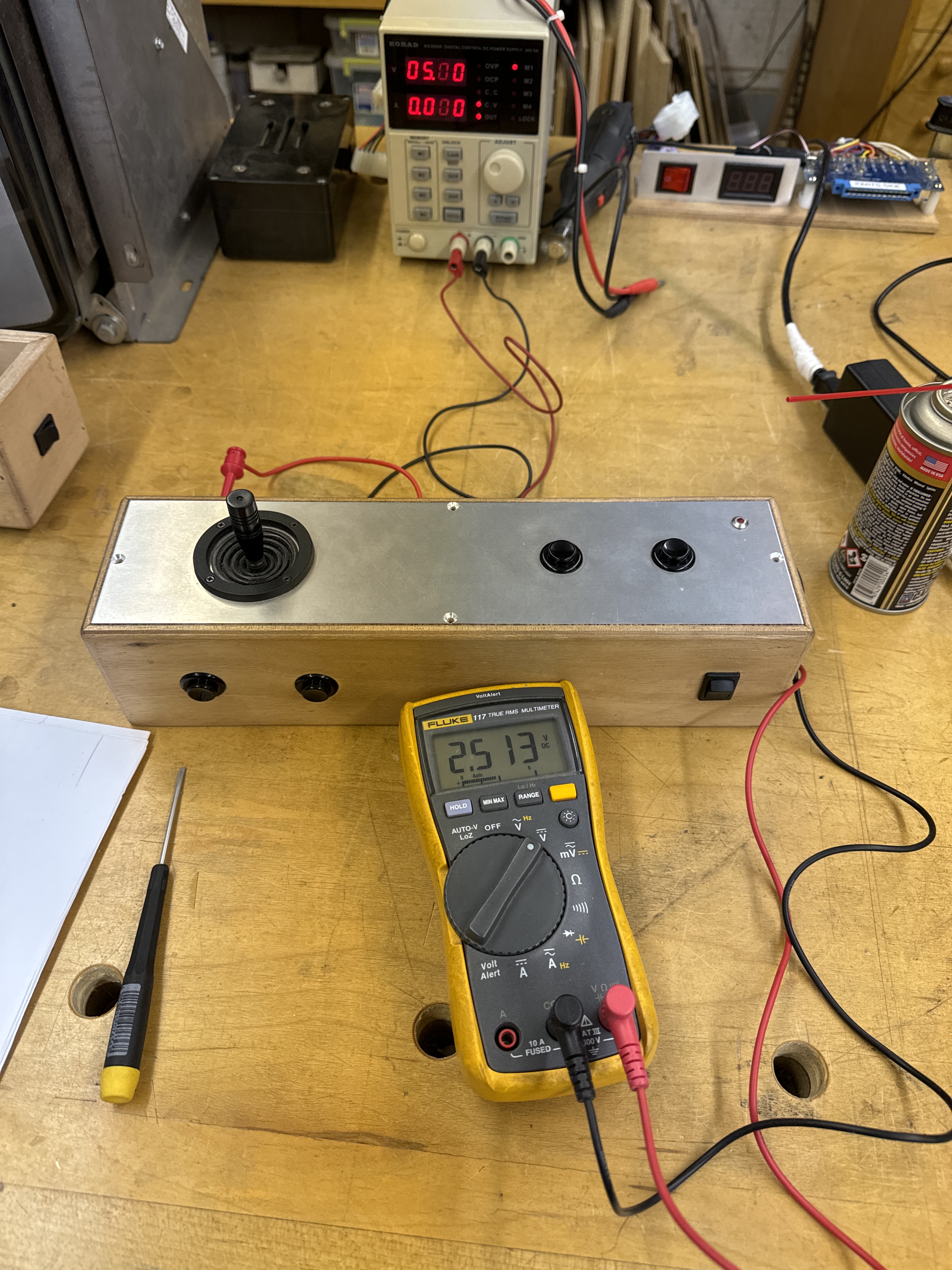
My bench adapter for BZ still works great. I had to add a couple wires and a ‘Y’ adapter – but that allowed me to use my analog joystick controller for Red Baron. This analog controller I also use for bench testing Star Wars and Food Fight. I’m calibrating the pots for center in this pic. An issue I was running into during testing was the plane was difficult to fly.. The game is very ‘jumpy’.
Centering the pot and then testing, I was getting a clean 0v <–> 5v range. However, on the diag screens – the pot position counters – which are clearly designed to count 0-255 would have the counts wrap/overflow if I used the full stick travel. I have a friend with an original Red Baron controller and he did a little measuring based on a hunch I had after looking at the pictures of it.. The controller does not use the entire travel of the pot. He measured -1V <– +1V from the center position. I went back to my controller and measured -2V and +2V before the DIAG numbers wrapped around. This is all very consistent with how the game feels. My bet is the +-1v plays pretty nicely with the original stick. Later games like Star Wars and Food Fight are not as sensitive to the pots as is Red Baron.
