
I got a few of these to take a look at and either verify or get working..
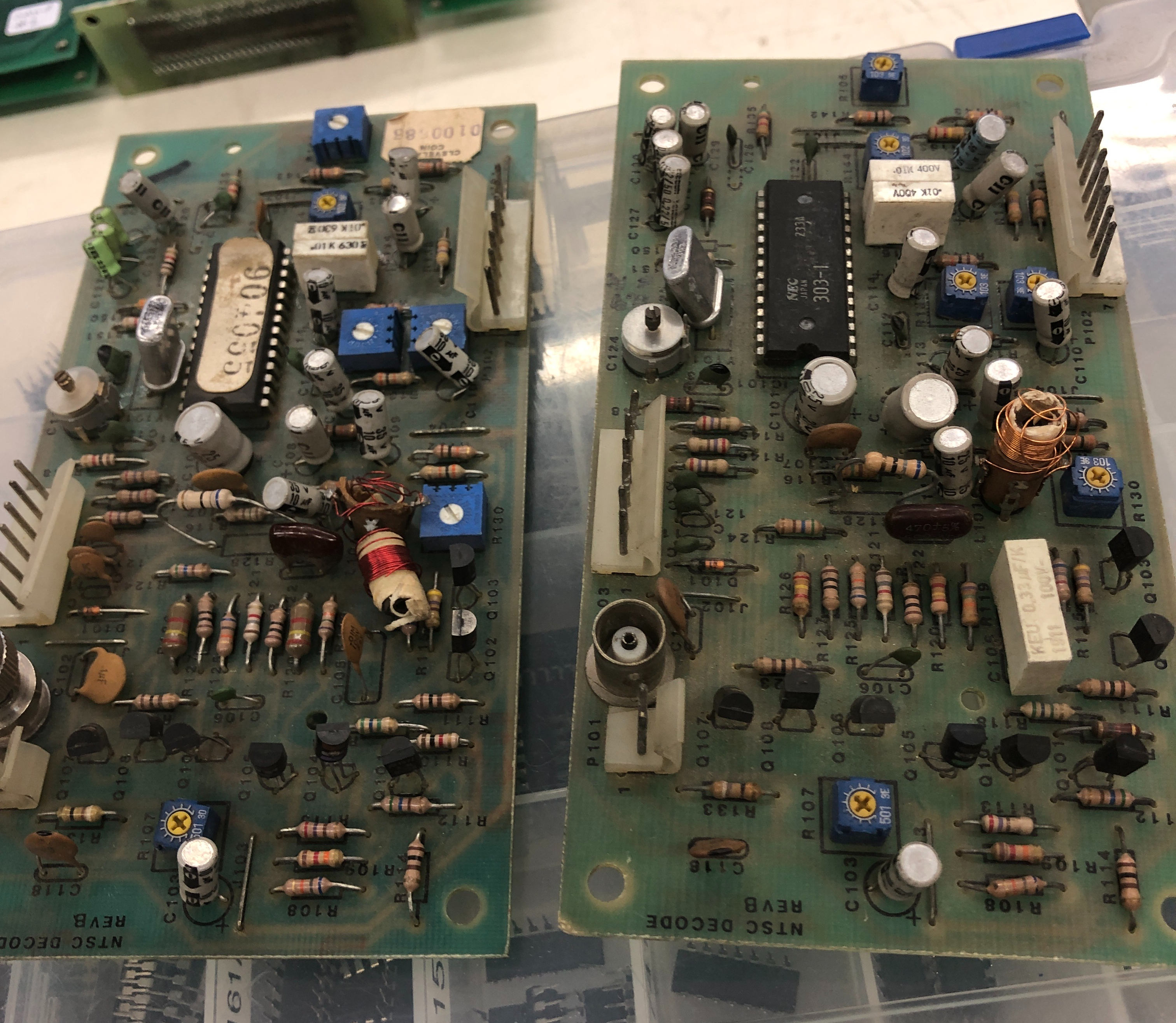
These are for the G07. Under the dirt they seem to be in decent condition except for the width coils (I’m assuming – I haven’t much more than a 4 page doc on these)
After cleaning up some cold solder joints and washing them.. I decided I was going to repair the one with the better of the 2 coils.. I’ve fixed some crazy stuff before.. but not these .. so I made up the steps as I went along..
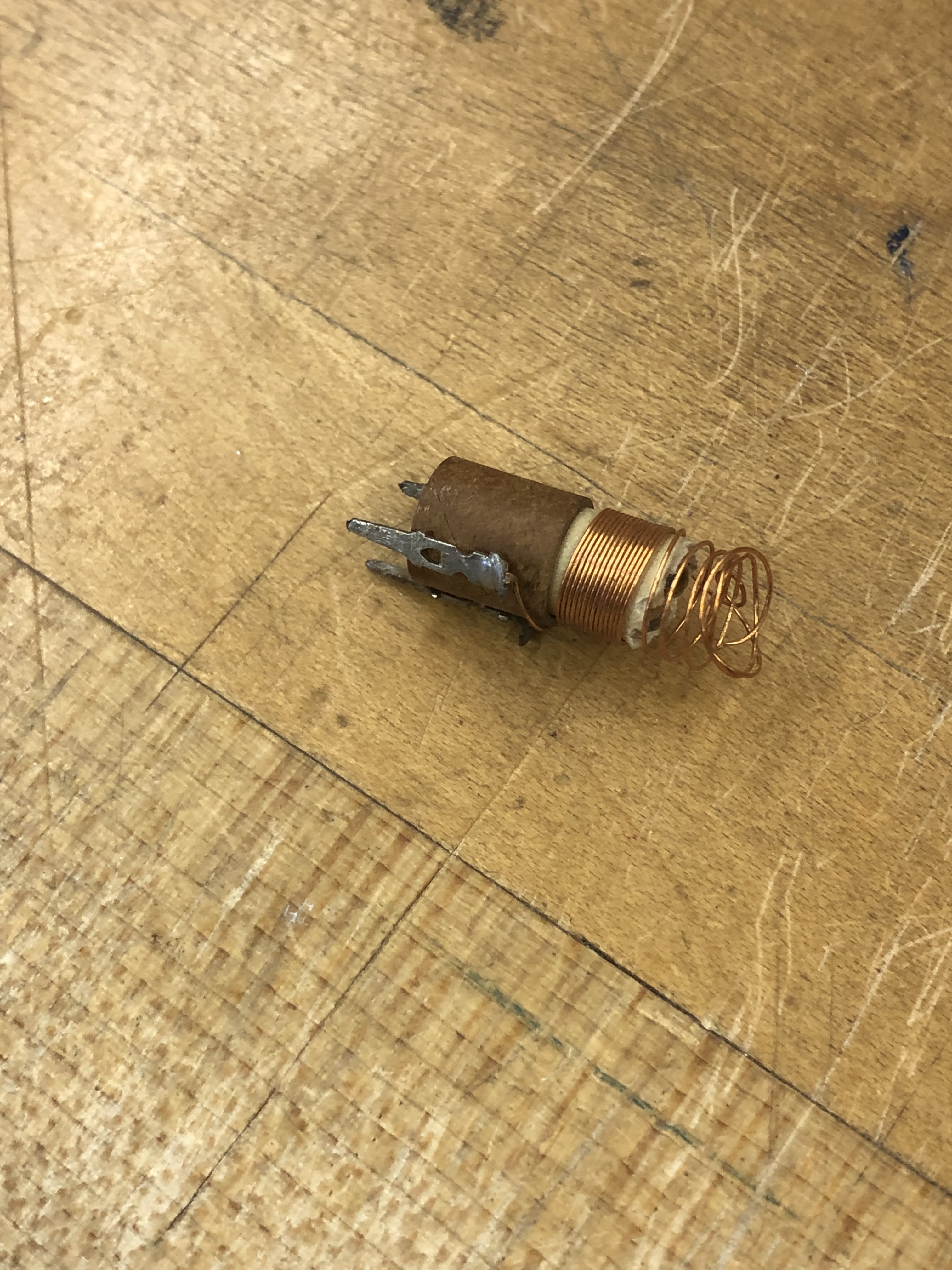
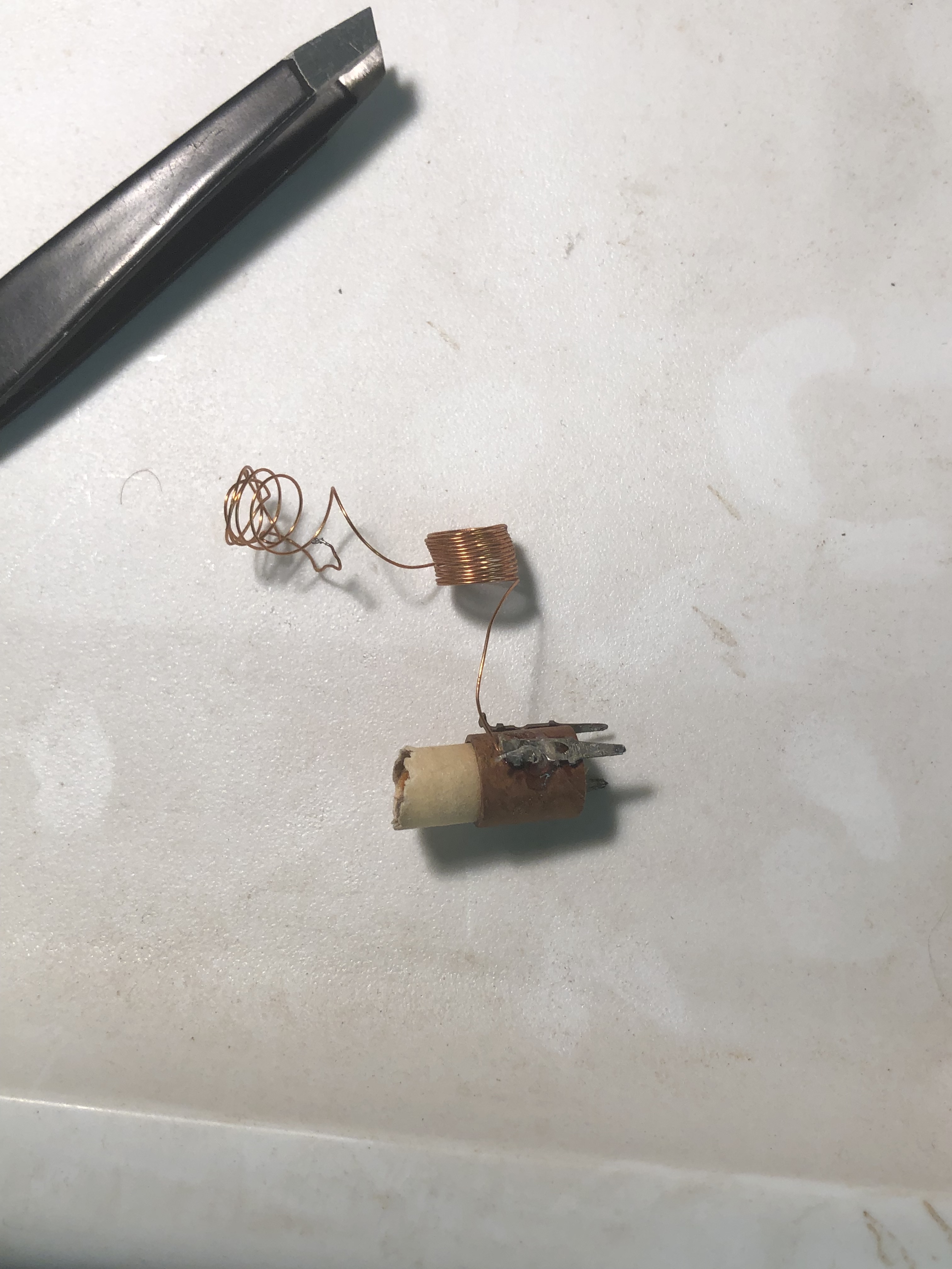
I started by pulling it off the board and was going to try to somehow rewind the coil over some sort of extension but keep it all in place, that wasn’t going to work. So I neatly got the coils off and to the side. Measuring with calipers – the inside was a perfect 1/4″ and the outside ~1/32″ thicker(ish).
At this point I decided to make a tube.. Found a 1/4″ aluminum rod I had in the shop.


I have a lathe which is not required of course, but it did make it easier to work on.. I spiraled a 1″ strip of printer paper around the rod – then used some Titebond II glue and wrapped 2 more layers. It didn’t go all that well. The paper wanted to tear because of the moisture in the glue and it kept buckling.. I didn’t need all of it to be smooth and neat – just an inch or so.. The other issue was the overlap didn’t have glue on it so it wanted to fall apart easily.. The alpha test result was not good enough. But I did learn one thing…
3 sheets of paper was actually too thick.
Take 2:
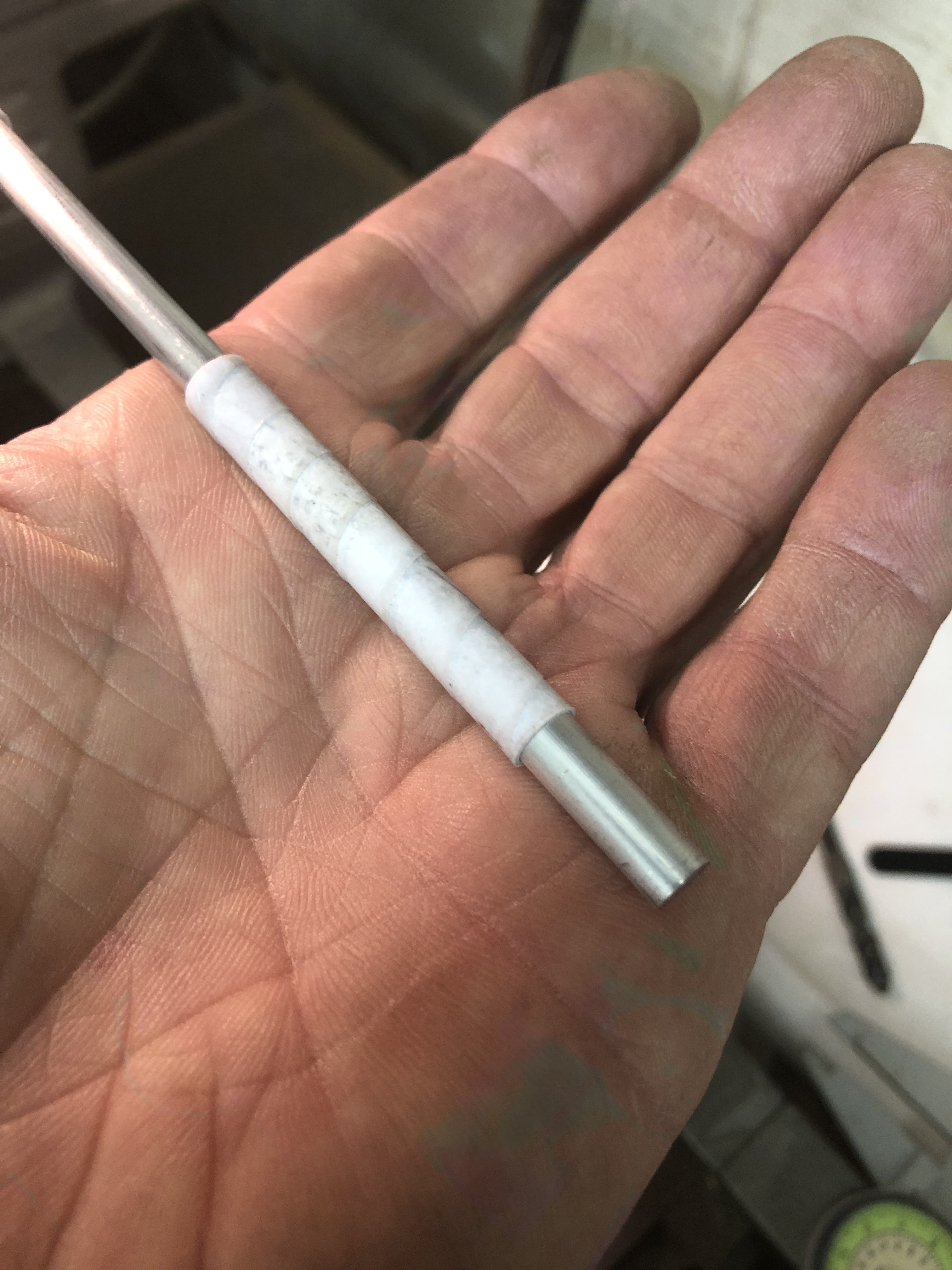
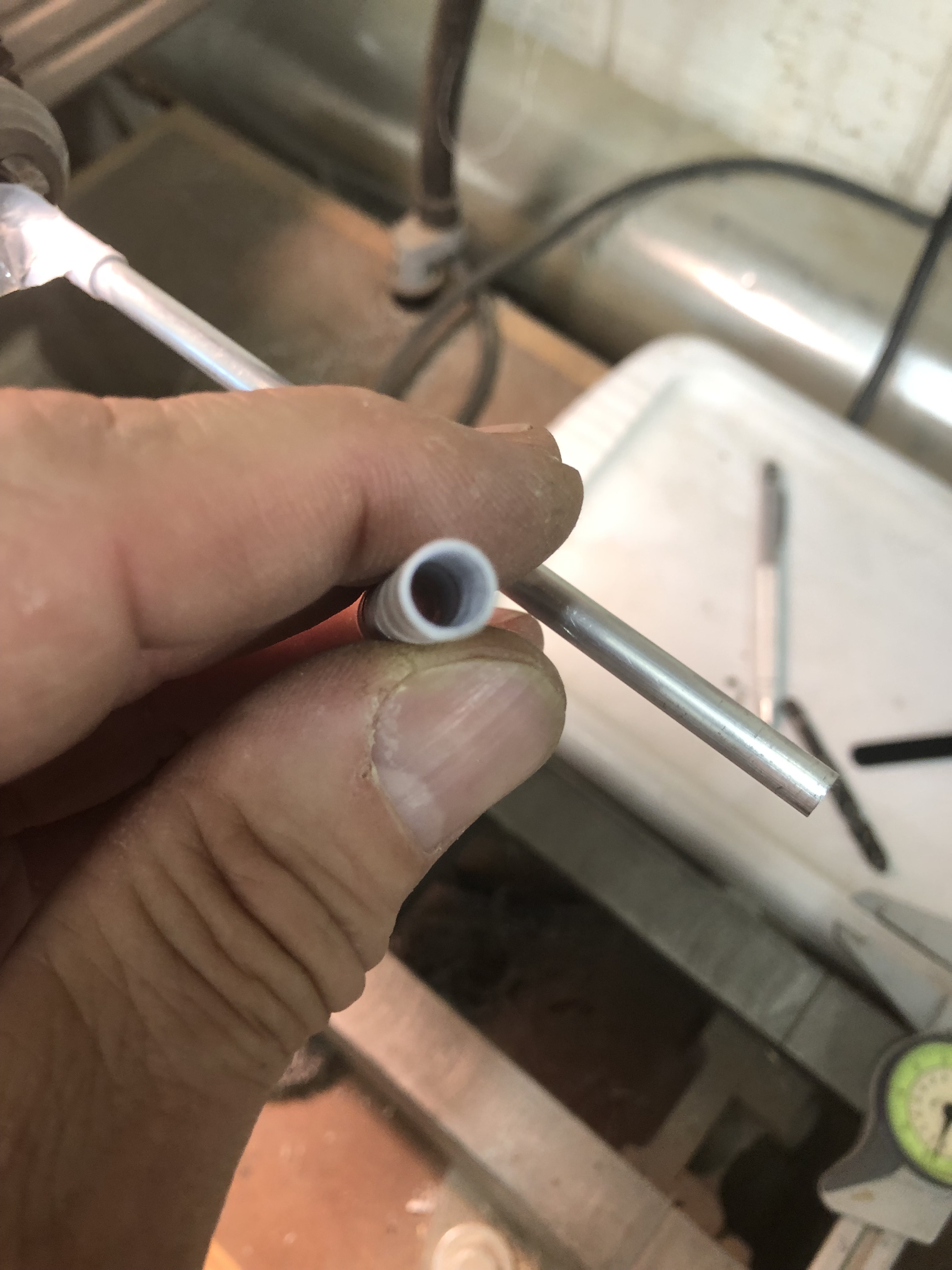
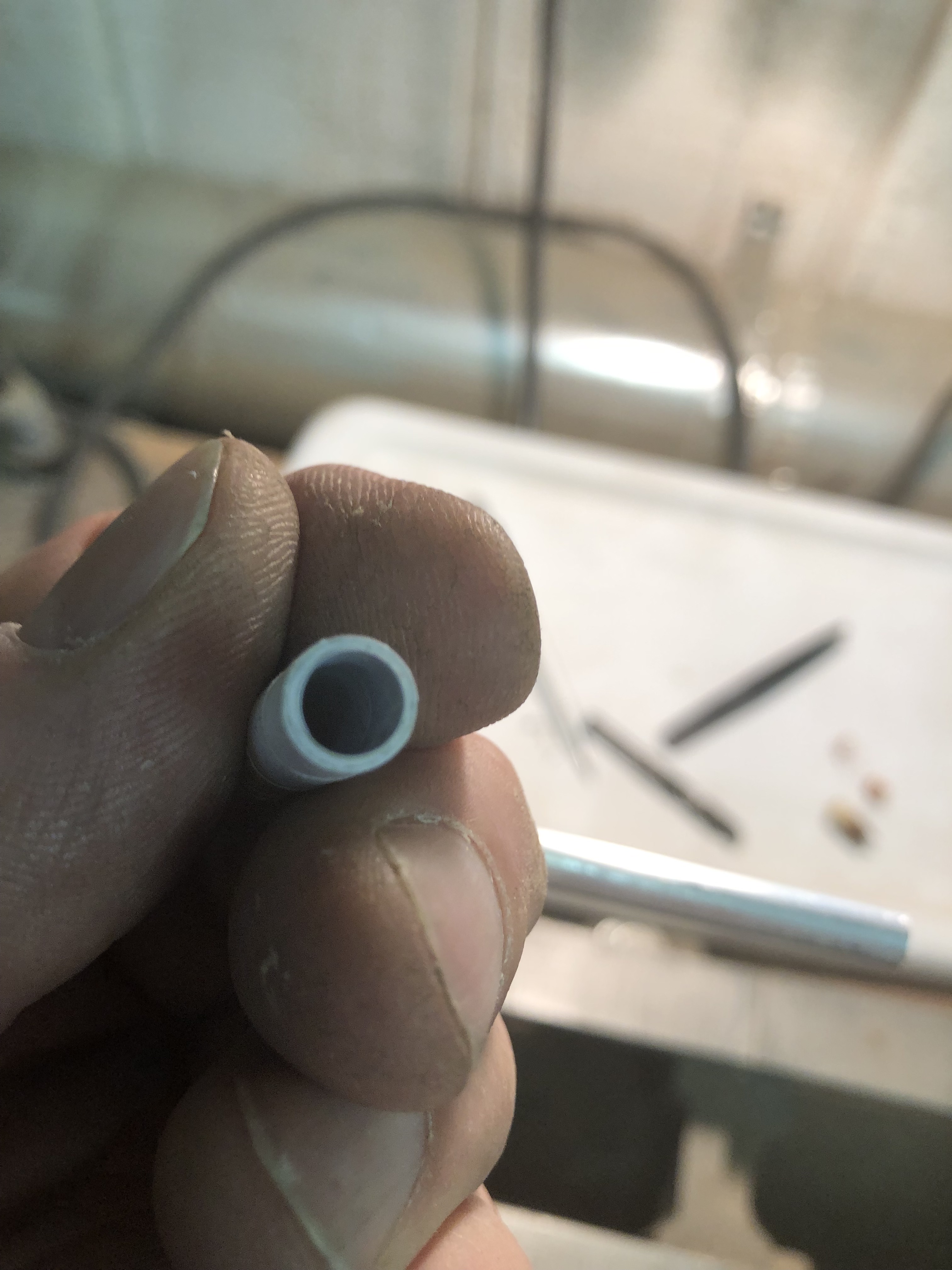
Started with the same first wrap of dry paper.. Don’t want to glue it to the rod, do I? Then I used 5 min epoxy and coated the paper on the mandrel and wrapped a second layer of paper on. Once it cured I coated the exterior in a thin layer of epoxy and let is set. Cut off the ends and slid it off the aluminum.. Perfect size!
Ok – now to wrap a coil.. I have no idea how ‘precise’ these need to be.. but it was 1983.. So I’m sure there is a little wiggle room.


New tube mated up to the old one. I trimmed the old tube as flush as I could, once it was close I ended up using a sanding block to square it off and make it flush. Here I made the decision to make the coil structural. I smeared on a thin coat of epoxy and wrapped the coil 22 times (just like it was..) and it worked out perfect.. the wire ended at the correct length. It took a few tries AND you have to uncoil the wire first, then wrap it.. I had to work out a few self induced kinks. The epoxy started getting tacky which actually made things easier. Once it was done I soldered the wire to the contact and cut the tube to length.
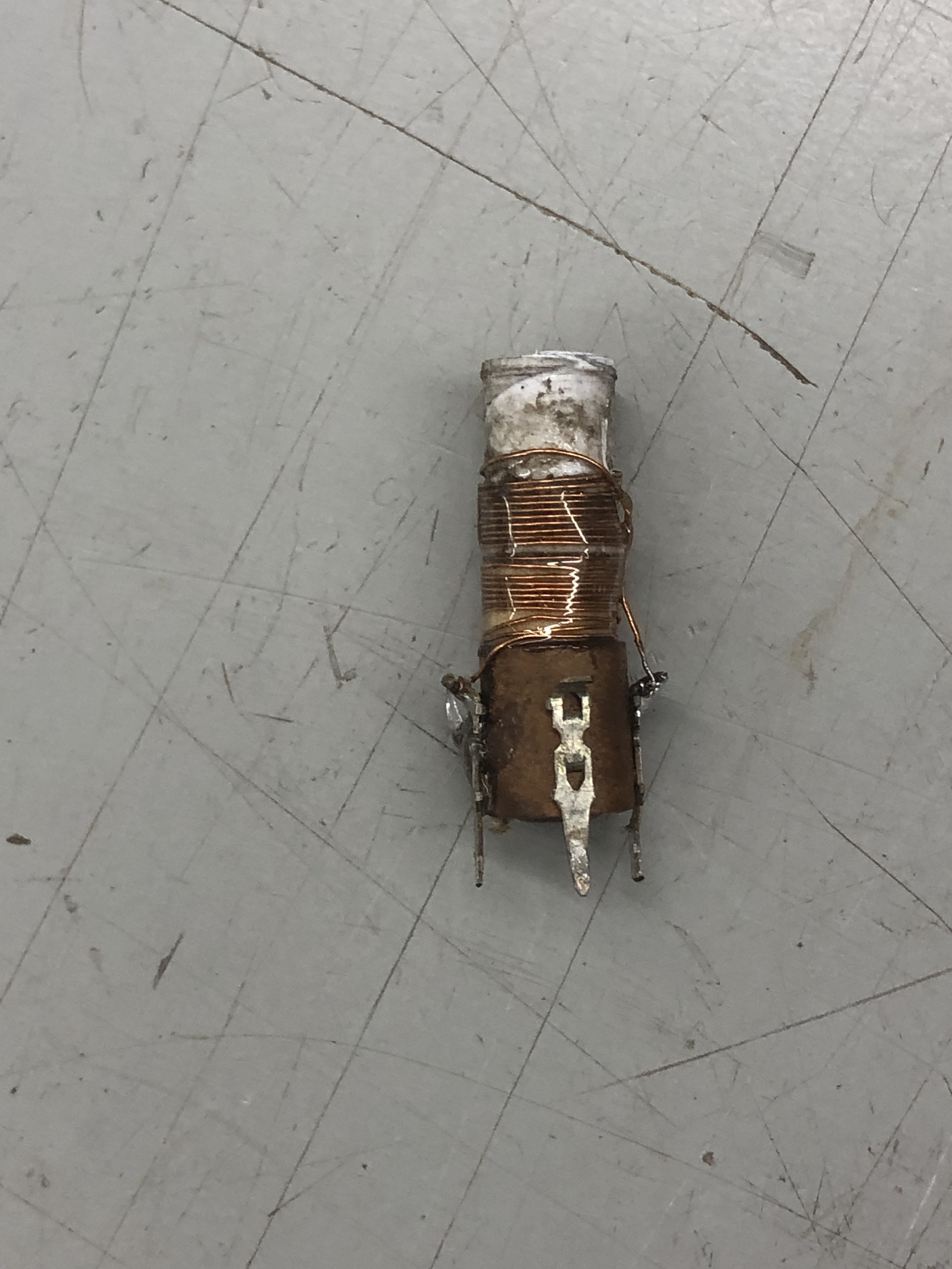
The last thing I did was coat it in UV cured resin to lock it all up. Dirty sticky finger prints and everything. I had turned the ferrite core all the way to the bottom – but I was able to spin it back up midway or so where a good one I have was positioned.
The board it came out of won’t sync horizontally.. screen keeps rolling (maybe the IC??) So I swapped it over to the board with the really destroyed coil..

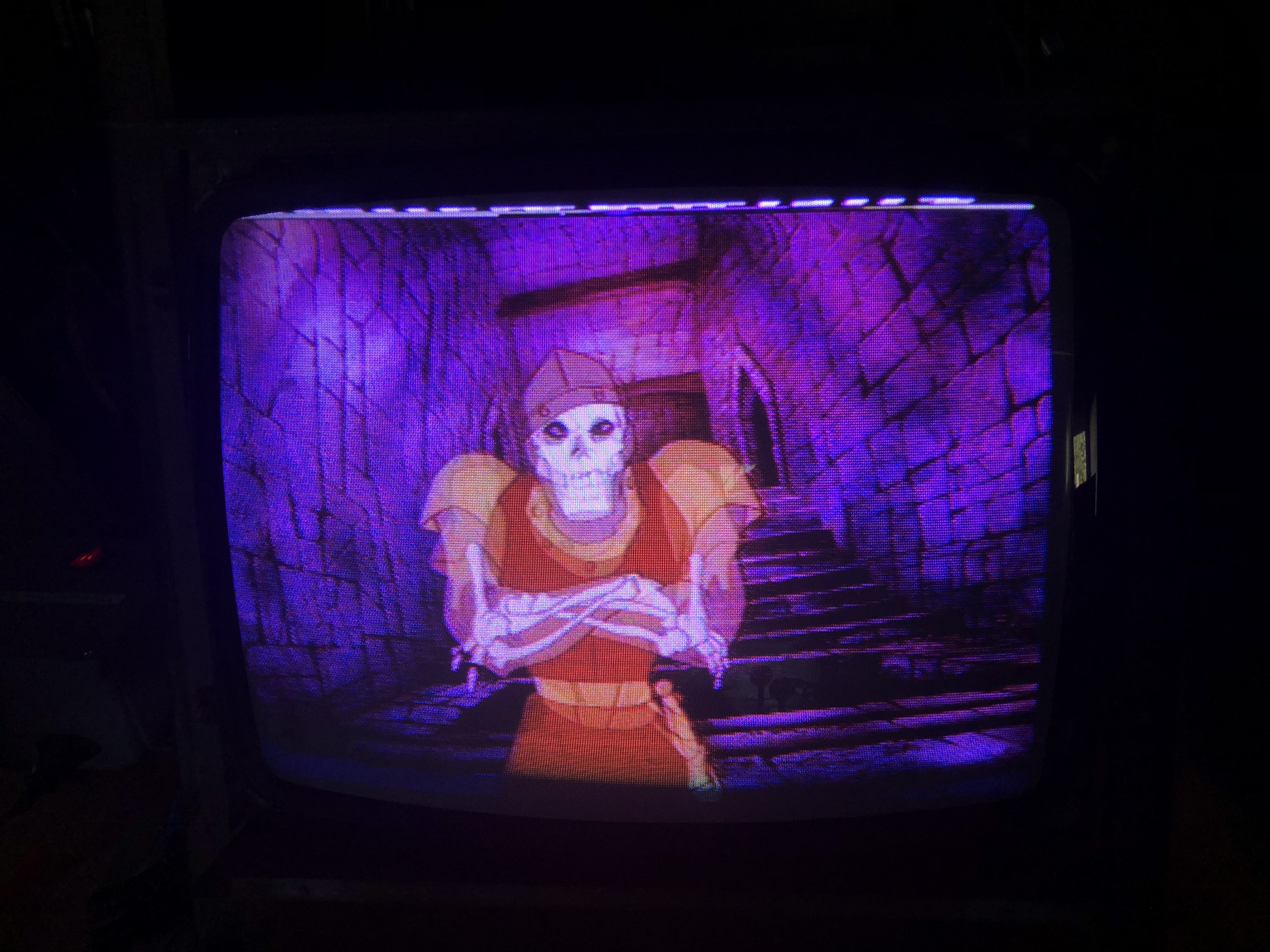
I’m calling that working!
Now for the really busted one… I decided to give it a shot
Turns out, it’s easier to make a new one than to try to repair the old one.. not surprising..


The ferrite threaded inside easily. I lubricated it with just a little wax to get it to spin nicely. The toughest part was getting the legs to stay on.. Next time I’ll wrap them with something to keep them in place.. I used double stick tape to keep the windings from springing loose before soldering the end connection. I learned this because …. I got to wind it twice..
It seems to work fine.. the board needs more work.. But I think I’ll figure that part out..
